Refrigerant Purifcation Apparatus
Liu; Hua ; et al.
U.S. patent application number 17/040408 was filed with the patent office on 2021-01-28 for refrigerant purifcation apparatus. The applicant listed for this patent is Gree Electric Appliances, Inc. of Zhuhai. Invention is credited to Dongbing Hu, Haili Hu, Lishu Hu, Nan Jiang, Hua Liu, Ying Zhang, Zhiping Zhang.
| Application Number | 20210025629 17/040408 |
| Document ID | / |
| Family ID | 1000005168340 |
| Filed Date | 2021-01-28 |

| United States Patent Application | 20210025629 |
| Kind Code | A1 |
| Liu; Hua ; et al. | January 28, 2021 |
Refrigerant Purifcation Apparatus
Abstract
A refrigerant purification apparatus, comprising a main shell and a separation baffle, a liquid separation space and a liquid collection space located under the liquid separation space are formed in the main shell; the liquid separation space in communication with the liquid collection space by means of a collection pipe. The baffle is provided at a position adjacent to a first refrigerant inlet within the liquid separation space to collide with moisture-containing refrigerant injected by means of the first refrigerant inlet, such that the refrigerant and the water in the water-containing refrigerant are separated and layered in the liquid separation space; the pipe configured to introduce the refrigerant located at a lower layer in the liquid separation space into the liquid collection space; and a water outlet configured to discharge the moisture located at a upper layer in the liquid separation space.
| Inventors: | Liu; Hua; (Zhuhai, Guangdong, CN) ; Zhang; Zhiping; (Zhuhai, Guangdong, CN) ; Hu; Haili; (Zhuhai, Guangdong, CN) ; Hu; Dongbing; (Zhuhai, Guangdong, CN) ; Hu; Lishu; (Zhuhai, Guangdong, CN) ; Zhang; Ying; (Zhuhai, Guangdong, CN) ; Jiang; Nan; (Zhuhai, Guangdong, CN) | ||||||||||
| Applicant: |
|
||||||||||
|---|---|---|---|---|---|---|---|---|---|---|---|
| Family ID: | 1000005168340 | ||||||||||
| Appl. No.: | 17/040408 | ||||||||||
| Filed: | December 17, 2018 | ||||||||||
| PCT Filed: | December 17, 2018 | ||||||||||
| PCT NO: | PCT/CN2018/121534 | ||||||||||
| 371 Date: | September 22, 2020 |
| Current U.S. Class: | 1/1 |
| Current CPC Class: | F25B 2345/005 20130101; F25B 45/00 20130101 |
| International Class: | F25B 45/00 20060101 F25B045/00 |
Foreign Application Data
| Date | Code | Application Number |
|---|---|---|
| May 5, 2018 | CN | 201810422065.3 |
Claims
1. A refrigerant purification apparatus, comprising: a main shell, a liquid separation space and a liquid collection space being formed in the main shell, the liquid collection space being located below the liquid separation space, and the liquid separation space and the liquid collection space being in communication by a collection pipe, wherein the main shell is provided with a first refrigerant inlet and a water outlet in communication with the liquid separation space, and the main shell is provided with a first refrigerant outlet in communication with the liquid collection space; a separation baffle, provided in the liquid separation space at a position adjacent to the first refrigerant inlet, the separation baffle configured to collide with a water-containing refrigerant injected from the first refrigerant inlet, so that refrigerant and water in the water-containing refrigerant are separated and layered in the liquid separation space, the collection pipe configured to introduce the refrigerant located at a lower layer within the liquid separation space into the liquid collection space, and the water outlet configured to discharge the water located at a upper layer within the liquid separation space.
2. The refrigerant purification apparatus as claimed in claim 1, wherein the water outlet is vertically higher than the collection pipe.
3. The refrigerant purification apparatus as claimed in claim 1, further comprising a water-separation sleeve being sleeved outside a collection port of the collection pipe, an upper opening of the water-separation sleeve being higher than the collection port, and a lower opening of the water-separation sleeve being lower than the collection port.
4. The refrigerant purification apparatus as claimed in claim 1, wherein the separation baffle comprises: a side baffle vertically disposed in the liquid separation space; and an upper baffle horizontally disposed on the top of the side baffle.
5. The refrigerant purification apparatus as claimed in claim 4, wherein the separation baffle further comprises a lower baffle, the lower baffle is disposed at the bottom of the side baffle, and the lower baffle separate the liquid separation space and the liquid collection space in the main shell.
6. The refrigerant purification apparatus as claimed in claim 1, wherein a gas collection space is formed in the main shell and located above the liquid separation space and communicates with the liquid separation space, the gas collection space configured to collect a gaseous refrigerant separated from the water-containing refrigerant, and the main shell is provided with an air outlet in communication with the gas collection space.
7. The refrigerant purification apparatus as claimed in claim 6, further comprising a filter, the filter being disposed in the gas collection space to filter the gaseous refrigerant separated from the water-containing refrigerant.
8. The refrigerant purification apparatus as claimed in claim 7, wherein the filter comprises two porous baffles and a gas-liquid filtering net disposed between the two porous baffles.
9. The refrigerant purification apparatus as claimed in claim 6, wherein the main shell is provided with a pressure measurement port in communication with the gas collection space.
10. The refrigerant purification apparatus as claimed in claim 6, further comprising: a sub-shell sleeved on the main shell, the sub-shell being adjacent to the gas collection space, a heat exchange space being formed between the sub-shell and the main shell, and on the sub-shell disposed a second refrigerant inlet and a second refrigerant outlet in communication with the heat exchange space.
11. The refrigerant purification apparatus as claimed in claim 10, wherein the second refrigerant inlet is located below the second refrigerant outlet.
12. The refrigerant purification apparatus as claimed in claim 10, further comprising a viewing window, the viewing window being mounted on at least one of the main shell and the sub-shell.
13. The refrigerant purification apparatus as claimed in claim 12, wherein a plurality of viewing windows are disposed at intervals in a vertical direction.
Description
CROSS-REFERENCE TO RELATED APPLICATIONS
[0001] This application is the United States national phase of International Application No. PCT/CN2018/121534 filed Dec. 17, 2018, and claims priority to Chinese Patent Application No. 201810422065.3 filed May 5, 2018, the disclosures of which are hereby incorporated by reference in their entirety.
BACKGROUND OF THE INVENTION
Technical Field
[0002] The present disclosure relates to the field of air conditioners, in particular, to a refrigerant purification apparatus and a refrigerant unit.
Background
[0003] When using an existing refrigerant unit, external water may enter the refrigerant system. Once water enters the refrigerant system, it would adversely affect heat transfer and the stability of the refrigerant unit.
[0004] Existing refrigerant purification apparatus could not remove the water in the refrigerant systems, so the above problems still affect the operation of the refrigerant unit.
SUMMARY OF THE INVENTION
[0005] In order to solve the problem of refrigerant purification apparatus in the prior art unable to remove water in refrigerant systems, embodiments of the present disclosure provide a refrigerant purification apparatus and a refrigerant unit.
[0006] An embodiment of the present application provides a refrigerant purification apparatus, comprising: a main shell, a liquid separation space and a liquid collection space being formed in the main shell, the liquid collection space being located below the liquid separation space, and the liquid separation space and the liquid collection space being in communication by a collection pipe, wherein the main shell is provided with a first refrigerant inlet and a water outlet in communication with the liquid separation space, and the main shell is also provided with a first refrigerant outlet in communication with the liquid collection space; a separation baffle, provided in the liquid separation space at a position adjacent to the first refrigerant inlet, the separation baffle configured for colliding with a water-containing refrigerant injected from the first refrigerant inlet, so that refrigerant and water in the water-containing refrigerant are separated and layered in the liquid separation space, the collection pipe configured to introduce the refrigerant located at a lower layer within the liquid separation space into the liquid collection space, and the water outlet configured to discharge the water located at a upper layer within the liquid separation space.
[0007] In one embodiment, the water outlet is vertically higher than the collection pipe.
[0008] In one embodiment, the refrigerant purification apparatus further comprises a water-separation sleeve, the water-separation sleeve is sleeved outside a collection port of the collection pipe, the upper opening of the water-separation sleeve is higher than the collection port, and the lower opening of the water-separation sleeve is lower than the collection port.
[0009] In one embodiment, the separation baffle comprises: a side baffle, vertically disposed in the liquid separation space; and an upper baffle, horizontally disposed on the top of the side baffle.
[0010] In one embodiment, the separation baffle further comprises a lower baffle, the lower baffle is disposed at the bottom of the side baffle, and the lower baffle separates the liquid separation space and the liquid collection space in the main shell.
[0011] In one embodiment, a gas collection space is formed in the main shell, and the gas collection space is located above the liquid separation space and communicates with the liquid separation space. The gas collection space configured to collect the gaseous refrigerant separated from the water-containing refrigerant. The main shell is provided with an air outlet in communication with the gas collection space.
[0012] In one embodiment, the refrigerant purification apparatus further comprises a filter, the filter being disposed in the gas collection space to filter the gaseous refrigerant separated from the water-containing refrigerant.
[0013] In one embodiment, the filter comprises two porous baffles and a gas-liquid filtering net disposed between the two porous baffles.
[0014] In one embodiment, the main shell is provided with a pressure measurement port in communication with the gas collection space.
[0015] In one embodiment, the refrigerant purification apparatus further comprises: a sub-shell sleeved on the main shell and adjacent to the gas collection space, and a heat exchange space being formed between the sub-shell and the main shell, on the sub-shell disposed a second refrigerant inlet and a second refrigerant outlet in communication with the heat exchange space.
[0016] In one embodiment, the second refrigerant inlet is located below the second refrigerant outlet.
[0017] In one embodiment, the refrigerant purification apparatus further comprises a viewing window, the viewing window being mounted on at least one of the main shell and the sub-shell.
[0018] In one embodiment, there are a plurality of viewing windows, and the plurality of viewing windows disposed at intervals in a vertical direction.
[0019] In the above embodiments, the water-containing refrigerant is injected into the liquid collection space from the first refrigerant inlet, and the water-containing refrigerant is sprayed onto the separation baffle for collision, which is beneficial to the separation of the refrigerant and the water in the water-containing refrigerant. Subsequently, the refrigerant and the water would be deposited in the liquid separation space. Since the density of water is less than the density of the refrigerant, the water would float above the refrigerant. Then, the refrigerant located at the lower layer within the liquid separation space is introduced, by the collection pipe, into the liquid collection space, and then the refrigerant is discharged from the first refrigerant outlet. In this way, water and refrigerant could be effectively separated from the water-containing refrigerant, ensuring the stability of the operation of the refrigerant unit.
BRIEF DESCRIPTION OF THE DRAWINGS
[0020] The drawings constituting a part of the present disclosure intend to provide a further understanding of the present disclosure. The embodiments of the present disclosure and their descriptions are used to illustrate the present disclosure and are not intended to limit the present disclosure. In the drawings:
[0021] FIG. 1 is a schematic structural view of an embodiment of a refrigerant purification apparatus illustrated from a first perspective according to the present disclosure;
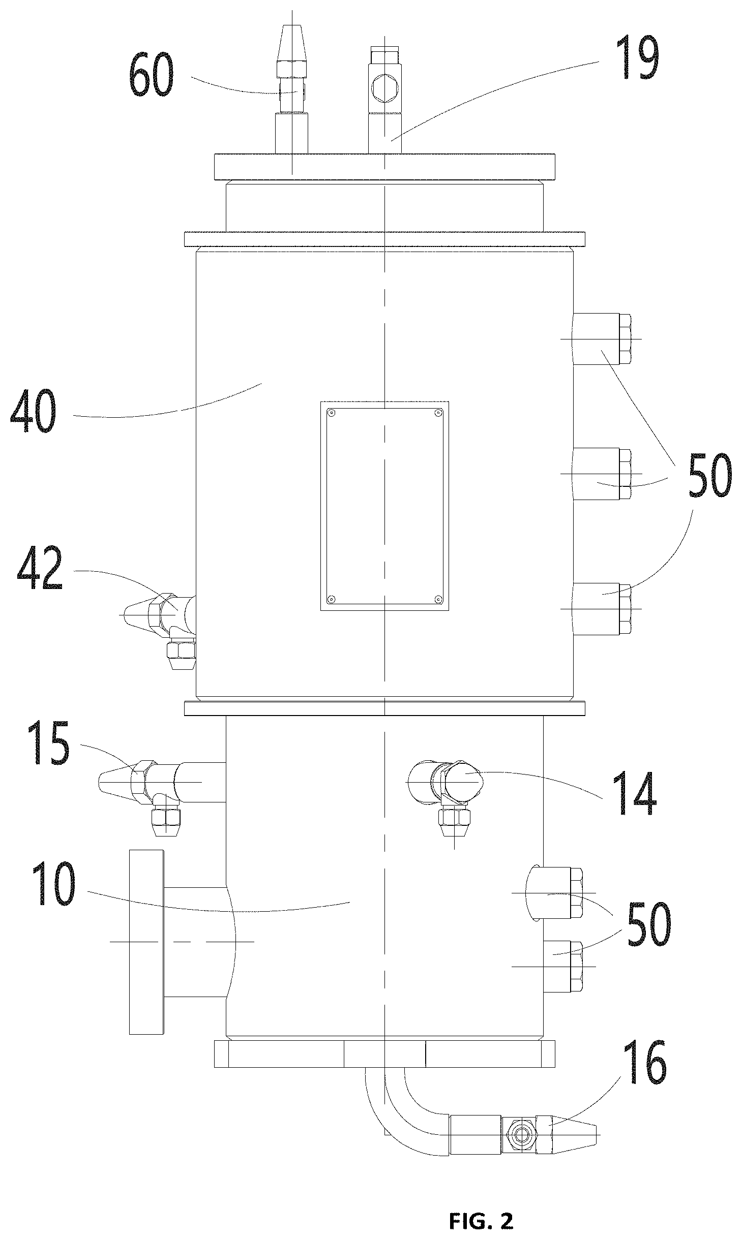
[0022] FIG. 2 is a schematic structural view of the refrigerant purification apparatus of FIG. 1 illustrated from a second perspective.
DETAILED DESCRIPTION OF THE INVENTION
[0023] In order to make the objectives, technical solutions and advantages of the present disclosure clearer, the present disclosure would be described in further details with embodiments and accompanying drawings. Here, the exemplary embodiments of the present disclosure and the description thereof are used to illustrate the present disclosure, but are not intended to limit the present disclosure.
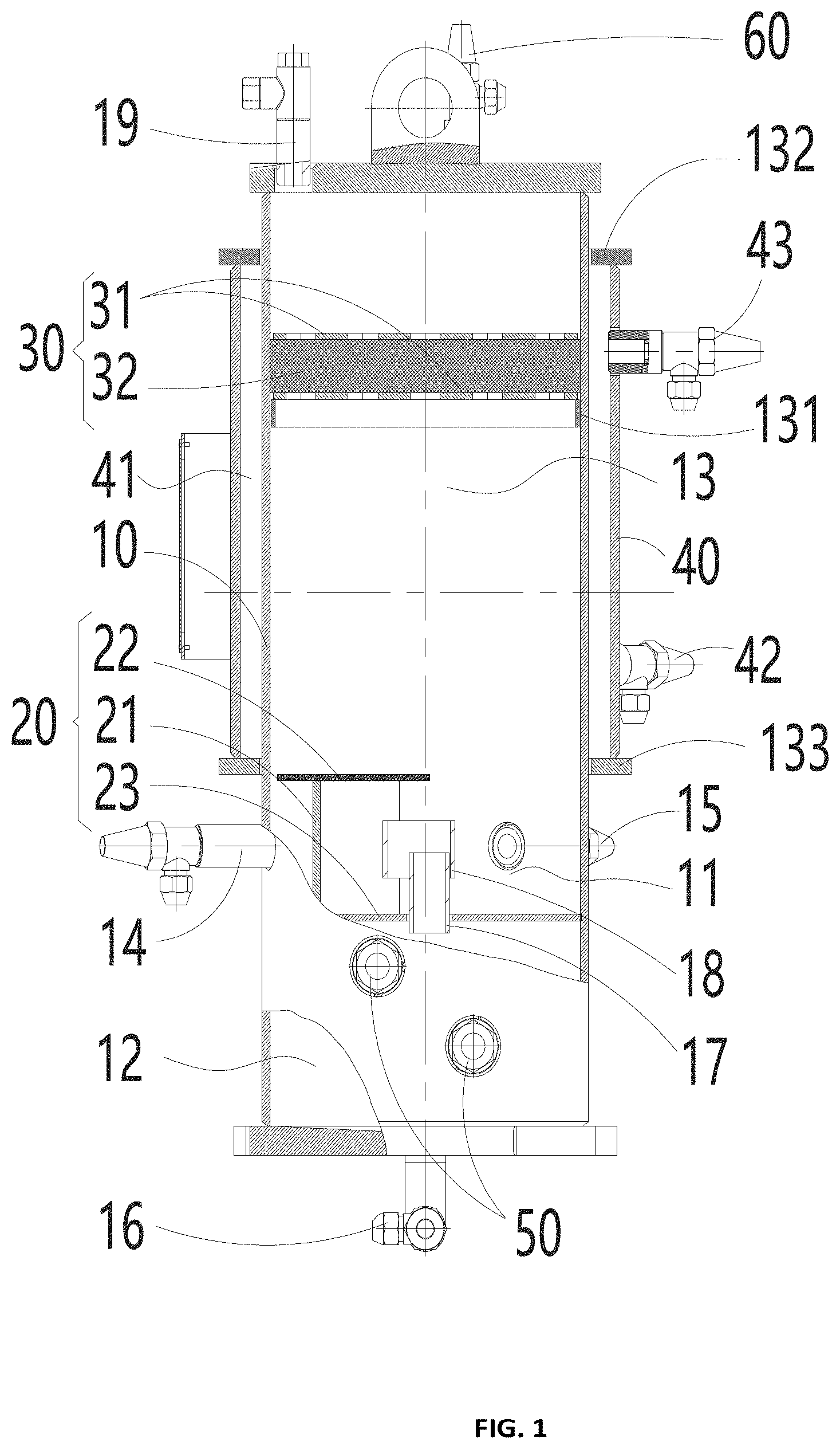
[0024] FIG. 1 and FIG. 2 show an embodiment of the refrigerant purification apparatus of the present disclosure. The refrigerant purification apparatus comprises a main shell 10 and a separation baffle 20. A liquid separation space 11 and a liquid collection space 12 are formed in the main shell 10. The liquid collection space 12 is located below the liquid separation space 11, and the liquid separation space 11 and the liquid collection space 12 communicate with each other through a collection pipe 17. The main shell 10 is provided with a first refrigerant inlet 14 and a water outlet 15 in communication with the liquid separation space 11, and the main shell 10 is also provided with a first refrigerant outlet 16 in communication with the liquid collection space 12. The separation baffle 20 is disposed in the liquid separation space 11 at a position adjacent to the first refrigerant inlet 14, and the separation baffle 20 is configured to collide with the water-containing refrigerant injected from the first refrigerant inlet 14, so that the refrigerant and the water in the water-containing refrigerant are separated and layered in the liquid separation space 11. The collection pipe 17 introduces the refrigerant located in a lower layer within the liquid separation space 11 into the liquid collection space 12, and the water outlet 15 discharges the water located in a upper layer within the liquid separation space 11.
[0025] By applying the technical solution of the present disclosure, the water-containing refrigerant is injected into the liquid collection space 12 through the first refrigerant inlet 14. The water-containing refrigerant is sprayed onto the separation baffle 20 for collision, which is beneficial to the separation of the refrigerant and the water in the water-containing refrigerant. Subsequently, the refrigerant and water would be deposited in the liquid separation space 11. Since the density of water is less than the density of the refrigerant, the water would float above the refrigerant. Then, the collection pipe 17 would introduce the refrigerant located in the lower layer within the liquid separation space 11 into the liquid collection space 12 and then be discharged from the first refrigerant outlet 16; the water located in the upper layer within the liquid separation space 11 would be discharged by water outlet 15. In this way, water and refrigerant would be effectively separated from the water-containing refrigerant, ensuring the stability of the operation of the refrigerant unit.
[0026] As shown in FIG. 1, as a preferred embodiment, the water outlet 15 is higher than the collection pipe 17 in a vertical direction. In this way, in conformity with the principle that the density of water is less than the density of refrigerant, it is easier to separate water and refrigerant.
[0027] As a preferred embodiment, as shown in FIG. 1, the refrigerant purification apparatus further comprises a water-separation sleeve 18. The water-separation sleeve 18 is sleeved outside the collection port of the collection pipe 17. The upper opening of the water-separation sleeve 18 is higher than the collection port, and the lower opening of the water-separation sleeve 18 is lower than the collection port. When separating water and refrigerant, since the liquid level between the water and the refrigerant may change, a water-separation sleeve 18 is provided outside the collection port of the collection pipe 17 to separate a large portion of water whose liquid level is below the collection port, so as to prevent excessive water from entering the collection port as the liquid level changes. In this way, the separation efficiency of the water-containing refrigerant is improved. In the technical solution of this embodiment, the throttle area of the water-separation sleeve 18 is larger than the throttle area of the collection pipe 17.
[0028] As shown in FIG. 1, as an optional embodiment, the separation baffle 20 comprises a side baffle 21 and an upper baffle 22. The side baffle 21 is vertically disposed in the liquid separation space 11, and the upper baffle 22 is horizontally disposed on the top of the side baffle 21. When the first refrigerant inlet 14 sprays the water-containing refrigerant toward the side baffle 21, the water-containing refrigerant would be sputtered from the side baffle 21 toward the surroundings, and the upper baffle 22 could prevent the water-containing refrigerant from splashing upward. At the same time, it could avoid the instability of the liquid surface caused by the impact of the incoming liquid on the liquid surface, which is conducive to stable drainage. More preferably, the separation baffle 20 further comprises a lower baffle 23 that is disposed at the bottom of the side baffle 21. The lower baffle 23 separates the liquid separation space 11 and the liquid collection space 12 in the main shell 10, so that the lower baffle 23 could also separate spaces.
[0029] As a preferred embodiment, as shown in FIG. 1, a gas collection space 13 is further formed in the main shell 10. The gas collection space 13 is located above the liquid separation space 11 and communicates with the liquid separation space 11. During the separation of the water-containing refrigerant, a large amount of gaseous refrigerant would also be produced. The gas collection space 13 is used to collect the gaseous refrigerant separated from the water-containing refrigerant. The main shell 10 is provided with an air outlet 19 in communication with the gas collection space 13. In this way, the refrigerant purification apparatus of the present disclosure could also separate gaseous refrigerant. More preferably, the refrigerant purification apparatus further comprises a filter 30. The filter 30 is disposed in the gas collection space 13. The filter 30 is used to filter the gaseous refrigerant separated from the water-containing refrigerant. The filter 30 could filter water and impurities in the gaseous refrigerant. Optionally, in the technical solution of this embodiment, the filter 30 comprises two porous baffles 31 and a gas-liquid filter net 32 disposed between the two porous baffles 31, wherein the porous baffles 31 are used to fix gas-liquid filter net 32. As shown in FIG. 1, an inner support ring 131 is provided in the main shell 10, and the filter 30 is fixedly mounted on the inner support ring 131.
[0030] As shown in FIG. 1, as a preferred embodiment, the main shell 10 is provided with a pressure measurement port 60 in communication with the gas collection space 13. The refrigerant purification apparatus further comprises a pressure gauge, and the pressure gauge is disposed on the pressure measurement port 60. As shown in FIG. 1, the pressure measuring port 60 is provided at the top of the gas collecting space 13, and the output air pressure of the gas collecting space 13 is measured by the pressure gauge.
[0031] As shown in FIG. 1, the refrigerant purification apparatus further comprises a sub-shell 40. The sub-shell 40 is disposed on the main shell 10 and is adjacent to the air collection space 13. A heat exchange space 41 is formed between the sub-shell 40 and the main shell 10. The sub-shell 40 is provided with a second refrigerant inlet 42 and a second refrigerant outlet 43 in communication with the heat exchange space 41. Usually, the low-pressure refrigerant is introduced into the liquid separation space 11 through the first refrigerant inlet 14. The high-pressure refrigerant is introduced into the heat exchange space 41 through the second refrigerant inlet 42 to allow the high-pressure refrigerant to exchange heat with the low-pressure refrigerant steam in the gas collection space 13. The low-pressure refrigerant steam becomes superheated steam after heat exchange, which helps the refrigerant droplets entrained in the low-pressure refrigerant steam evaporate and become steam. Optionally, in the technical solution of this embodiment, the second refrigerant inlet 42 is located below the second refrigerant outlet 43. In addition, it is also feasible to dispose the second refrigerant inlet 42 above the second refrigerant outlet 43. In the technical solution of this embodiment, as shown in FIG. 1, an upper support ring 132 and a lower support ring 133 are provided outside the main shell 10, and the sub-shell 40 is fixed between the upper support ring 132 and the lower support ring 133.
[0032] As shown in FIGS. 1 and 2, the refrigerant purification apparatus further comprises a viewing window 50. The viewing window 50 is mounted on the main shell 10. The viewing window 50 provided on the main shell 10 helps to observe the liquid level when separating the water-containing refrigerant, so as to control the flow rate of the first refrigerant inlet 14 injected into the water-containing refrigerant. More preferably, the viewing window 50 is also mounted on the sub-shell 40 to help observation of the high-pressure refrigerant in the sub-shell 40. As a preferred embodiment, as shown in FIG. 1, there are a plurality of viewing windows 50, and the plurality of viewing windows 50 are disposed at intervals in a vertical direction, so as to observe the state within the refrigerant purification apparatus.
[0033] By using the refrigerant purification apparatus of the present disclosure, the water in the water-containing refrigerant could be effectively separated out, and the low-pressure refrigerant steam could also be used to cool the high-pressure refrigerant liquid to increase its supercooling degree. The filter 30 could also separate the liquid droplets entrained in the low-pressure refrigerant steam, to avoid liquid contained in incoming gas, and improve the stability of the unit.
[0034] The disclosure above is preferred embodiments of the present disclosure and is not intended to limit the present disclosure. For those skilled in the art, the embodiments of the present disclosure may have various modifications and changes. Any modification, equivalent replacement, improvement, etc. within the spirit and principles of the present disclosure should be included in the protection scope of the present disclosure.
* * * * *
D00000
D00001
D00002
XML
uspto.report is an independent third-party trademark research tool that is not affiliated, endorsed, or sponsored by the United States Patent and Trademark Office (USPTO) or any other governmental organization. The information provided by uspto.report is based on publicly available data at the time of writing and is intended for informational purposes only.
While we strive to provide accurate and up-to-date information, we do not guarantee the accuracy, completeness, reliability, or suitability of the information displayed on this site. The use of this site is at your own risk. Any reliance you place on such information is therefore strictly at your own risk.
All official trademark data, including owner information, should be verified by visiting the official USPTO website at www.uspto.gov. This site is not intended to replace professional legal advice and should not be used as a substitute for consulting with a legal professional who is knowledgeable about trademark law.