Gas Furnace
KIM; Jusu ; et al.
U.S. patent application number 16/938543 was filed with the patent office on 2021-01-28 for gas furnace. The applicant listed for this patent is LG ELECTRONICS INC.. Invention is credited to Doyong Ha, Yongki Jeong, Jusu KIM, Hansaem Park, Janghee Park.
| Application Number | 20210025621 16/938543 |
| Document ID | / |
| Family ID | 1000004989159 |
| Filed Date | 2021-01-28 |


View All Diagrams
| United States Patent Application | 20210025621 |
| Kind Code | A1 |
| KIM; Jusu ; et al. | January 28, 2021 |
GAS FURNACE
Abstract
Provided is a gas furnace. The gas furnace includes: a manifold with an exhaust port for discharging fuel gas; a nozzle attached to the exhaust port; a burner for burning a mixture of air and fuel gas ejected from the nozzle; a primary heat exchanger that provides a first flow path and allows a combustion gas produced by the combustion of the mixture to move through the first flow path; and a secondary heat exchanger located adjacent to the primary heat exchanger, that provides a second flow path and allows the combustion gas discharged from the primary heat exchanger to move through the second flow path, wherein the secondary heat exchanger includes: at least one tube forming the second flow path; and a baffle inserted into the at least one tube, the baffle including: a plate longitudinally extending in a lengthwise direction and twisted in the shape of a screw; and a plurality of holes formed to penetrate the plate.
| Inventors: | KIM; Jusu; (Seoul, KR) ; Ha; Doyong; (Seoul, KR) ; Jeong; Yongki; (Seoul, KR) ; Park; Janghee; (Seoul, KR) ; Park; Hansaem; (Seoul, KR) | ||||||||||
| Applicant: |
|
||||||||||
|---|---|---|---|---|---|---|---|---|---|---|---|
| Family ID: | 1000004989159 | ||||||||||
| Appl. No.: | 16/938543 | ||||||||||
| Filed: | July 24, 2020 |
| Current U.S. Class: | 1/1 |
| Current CPC Class: | F23D 14/22 20130101; F24H 9/0063 20130101; F24H 3/025 20130101; F23D 14/48 20130101 |
| International Class: | F24H 3/02 20060101 F24H003/02; F23D 14/22 20060101 F23D014/22; F23D 14/48 20060101 F23D014/48; F24H 9/00 20060101 F24H009/00 |
Foreign Application Data
| Date | Code | Application Number |
|---|---|---|
| Jul 26, 2019 | KR | 10-2019-0090923 |
Claims
1. A gas furnace comprising: a manifold with an exhaust port for discharging fuel gas; a nozzle attached to the exhaust port; a burner for burning a mixture of air and fuel gas ejected from the nozzle; a primary heat exchanger that provides a first flow path and allows a combustion gas produced by the combustion of the mixture to move through the first flow path; and a secondary heat exchanger located adjacent to the primary heat exchanger, that provides a second flow path and allows the combustion gas discharged from the primary heat exchanger to move through the second flow path, wherein the secondary heat exchanger comprises: at least one tube forming the second flow path; and a baffle inserted into the at least one tube, wherein the baffle comprises: a plate extending long in a lengthwise direction of the tube and twisted in the shape of a screw; and a plurality of holes formed to penetrate the plate.
2. The gas furnace of claim 1, wherein the plate comprises a plurality of segments, and the plurality of holes are formed in the plurality of segments, respectively.
3. The gas furnace of claim 1, wherein the plate comprises a plurality of segments, and the plurality of holes are formed in each of the plurality of segments.
4. The gas furnace of claim 1, wherein the plurality of holes are formed for each pitch of a screw pattern on the plate, and are sequentially arranged along the central axis of the tube.
5. The gas furnace of claim 1, wherein the plurality of holes are formed for each pitch of a screw pattern on the plate and arranged in an alternating fashion along the central axis of the tube.
6. The gas furnace of claim 1, wherein the plurality of holes comprises: a plurality of holes in a first row formed along the central axis of the tube; a plurality of holes in a second row formed along the central axis of the tube, spaced apart from the central axis of the tube; a plurality of holes in a third row formed along the central axis of the tube, spaced apart from the central axis of the tube, and facing the plurality of holes in the second row with respect to the central axis of the tube.
7. The gas furnace of claim 1, wherein the plurality of holes form cutouts on at least one edge of the plate in a width direction, and the cutouts have an overall triangular shape.
8. The gas furnace of claim 7, wherein the cutouts have an overall rectangular shape.
Description
CROSS-REFERENCE TO RELATED APPLICATION
[0001] This application claims the priority from Korean Patent Application No. 10-2019-0090923, filed on Jul. 26, 2019, in the Korean Intellectual Property Office, the disclosure of which is incorporated herein by reference in its entirety.
FIELD OF THE DISCLOSURE
[0002] The present disclosure relates to a gas furnace. More particularly, the present disclosure relates to a gas furnace with a baffle that can facilitate heat transfer and/or condensate water formation.
RELATED ART
[0003] Generally, a gas furnace is an apparatus that heats up a room by supplying air heated through heat exchange with a flame and high-temperature combustion gas produced by the combustion of a fuel gas.
[0004] The gas furnace may have a primary heat exchanger and a secondary heat exchanger. The secondary heat exchanger is generally a finned tube heat exchanger.
[0005] US 2006/0213499 A1 discloses a baffle that is inserted into a tube to enhance the heat transfer efficiency of the secondary heat exchanger.
[0006] However, the above-mentioned US 2006/0213499 A1 may have the problem of a pressure drop in the tube and a flow stagnation at the center of the tube, since the baffle is inserted into the tube. Another problem is that the power consumption of a fan increases with increasing resistance to gas flow in the tube with the baffle inserted in it. Other problems include condensate water standing in the tube into which the baffle is inserted.
SUMMARY OF THE DISCLOSURE
[0007] A first problem to be solved by the present disclosure is to provide a gas furnace that can alleviate the pressure drop in the tube.
[0008] A second problem to be solved by the present disclosure is to provide a gas furnace that can alleviate the stagnation of flow in the tube.
[0009] A third problem to be solved by the present disclosure is to provide a gas furnace that can reduce the power consumption of the fan by decreasing the resistance to gas flow in a heat exchanger.
[0010] A fourth problem to be solved by the present disclosure is to provide a gas furnace that can alleviate condensate water standing in the tube into which the baffle is inserted.
[0011] Technical problems to be solved by the present disclosure are not limited to the above-mentioned technical problems, and other technical problems not mentioned herein may be clearly understood by those skilled in the art from description below.
[0012] To solve the above-mentioned problems, there is provided a gas furnace according to an aspect of the present disclosure, including: a manifold with an exhaust port for discharging fuel gas; a nozzle attached to the exhaust port; a burner for burning a mixture of air and fuel gas ejected from the nozzle; a primary heat exchanger that provides a first flow path and allows a combustion gas produced by the combustion of the mixture to move through the first flow path; and a secondary heat exchanger located adjacent to the primary heat exchanger, that provides a second flow path and allows the combustion gas discharged from the primary heat exchanger to move through the second flow path, wherein the secondary heat exchanger includes: at least one tube forming the second flow path; and a baffle inserted into the at least one tube, wherein the baffle includes: a plate extending long in a lengthwise direction of the tube and twisted in the shape of a screw; and a plurality of holes formed to penetrate the plate.
[0013] According to another aspect of the present disclosure, the plate may include a plurality of segments, and the plurality of holes may be formed in the plurality of segments, respectively.
[0014] According to another aspect of the present disclosure, the plate may include a plurality of segments, and the plurality of holes may be formed in each of the plurality of segments.
[0015] According to another aspect of the present disclosure, the plurality of holes may be formed for each pitch of a screw pattern on the plate, and are sequentially arranged along the central axis of the tube.
[0016] According to another aspect of the present disclosure, the plurality of holes may be formed for each pitch of a screw pattern on the plate and arranged in an alternating fashion along the central axis of the tube.
[0017] According to another aspect of the present disclosure, the plurality of holes may include: a plurality of holes in a first row formed along the central axis of the tube; a plurality of holes in a second row formed along the central axis of the tube, spaced apart from the central axis of the tube; a plurality of holes in a third row formed along the central axis of the tube, spaced apart from the central axis of the tube, and facing the plurality of holes in the second row with respect to the central axis of the tube.
[0018] According to another aspect of the present disclosure, the plurality of holes may form cutouts on at least one edge of the plate in a width direction, and the cutouts may have an overall triangular shape.
[0019] According to another aspect of the present disclosure, the cutouts may have an overall rectangular shape.
[0020] Means for solving other problems not mentioned above will be easily deduced from the descriptions of embodiments of the present disclosure.
BRIEF DESCRIPTION OF THE DRAWINGS
[0021] FIG. 1 is a view illustrating an example of a gas furnace according to an exemplary embodiment of the present disclosure.
[0022] FIG. 2 is a view illustrating a part of the construction of the gas furnace according to the exemplary embodiment of the present disclosure.
[0023] FIG. 3 is a view illustrating another part of the construction of the gas furnace according to the exemplary embodiment of the present disclosure.
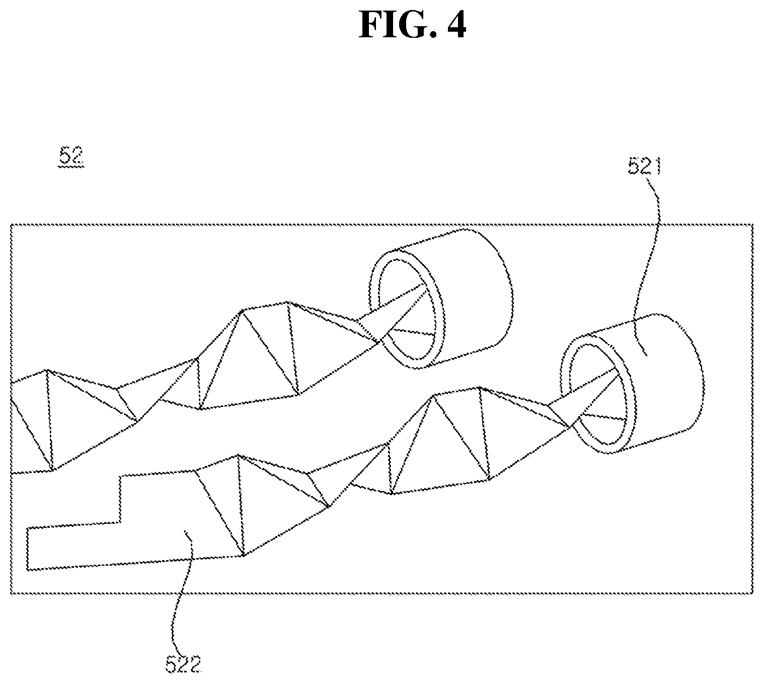
[0024] FIGS. 4 and 5 are views illustrating a construction in which a baffle is inserted into a heat exchanger tube according to the exemplary embodiment of the present disclosure.
[0025] FIGS. 6 to 13 are views illustrating various examples of the baffle according to the exemplary embodiment of the present disclosure.
DESCRIPTION OF EXEMPLARY EMBODIMENTS
[0026] Advantages and features of the present disclosure and methods for achieving them will be made clear from embodiments described below in detail with reference to the accompanying drawings. The present disclosure may, however, be embodied in many different forms and should not be construed as being limited to the embodiments set forth herein. Rather, these embodiments are provided so that this disclosure will be thorough and complete, and will fully convey the scope of the disclosure to those skilled in the art. The present disclosure is merely defined by the scope of the claims. Like reference numerals refer to like elements throughout the specification.
[0027] The present disclosure will be described with respect to a spatial orthogonal coordinate system illustrated in FIG. 2 and other figures where X, Y, and Z axes are orthogonal to each other. In this specification, the X axis, Y axis, and Z axis are defined assuming that the up-down direction is along the Z axis and the front-back direction is along the X axis. Each axis direction (X-axis direction, Y-axis direction, and Z-axis direction) refers to two directions in which each axis runs. Each axis direction with a `+` sign in front of it (+X-axis direction, +Y-axis direction, and +Z-axis direction) refers to a positive direction which is one of the two directions in which each axis runs. Each axis direction with a `-` sign in front of it (-X-axis direction, -Y-axis direction, and -Z-axis direction) refers to a negative direction which is the other of the two directions in which each axis runs.
[0028] Referring to FIGS. 1 and 2, the gas furnace 10 is an apparatus that heats up a room by supplying air heated through heat exchange with a flame and high-temperature combustion gas P produced by the combustion of a fuel gas R.
[0029] The gas furnace 10 according to the exemplary embodiment of the present disclosure includes a gas valve 20 that supplies a fuel gas R to a manifold 30, a burner 40 in which the fuel gas R released from the manifold 30 is mixed with air and flows in an air-fuel mixture, and a heat exchanger 50 through which a combustion gas P produced by the combustion of the air-fuel mixture in the burner 40 flows.
[0030] Furthermore, the gas furnace 10 include an inducer 70 for inducing a flow of combustion gas P to an exhaust pipe 80 through the heat exchanger 50, a blower 60 for blowing air around the heat exchanger 50 so that the air is supplied to a room, and a condensate water trap 90 for collecting condensate water produced in the heat exchanger 50 and/or the exhaust pipe 80 and discharging it.
[0031] The fuel gas R supplied through the gas valve 20 may include, for example, liquefied natural gas (LNG), which is natural gas that has been cooled down to liquid form, or liquefied petroleum gas (LPG), which is prepared by pressurizing gaseous by-products of petroleum refining into liquid form.
[0032] As the gas valve 20 opens or closes, the fuel gas R may be supplied to the manifold 30 or its supply may be cut off. Also, the amount of fuel gas R supplied to the manifold 30 may be regulated by adjusting the opening degree of the gas valve 20. As such, the gas valve 20 may regulate the heating power of the gas furnace 10. To this end, the gas furnace 10 may further include a control part for adjusting the opening or closing of the gas valve 20 or its opening degree.
[0033] The manifold 30 may guide the fuel gas R to the burner 40, and the fuel gas R, once introduced into the burner 40, may flow in a mixture with air.
[0034] The air-fuel mixture flowing through the burner 40 may be burnt due to flame ignition by an igniter. In this case, the combustion of the air-fuel mixture may produce a flame and a high-temperature combustion gas P.
[0035] The heat exchanger 50 may have a flow path through which the combustion gas P can flow.
[0036] Referring to FIGS. 2 and 3, the heat exchanger 50 may include a primary heat exchanger 51 and/or a secondary heat exchanger 52.
[0037] The primary heat exchanger 51 may be placed with one end being adjacent to the burner 40. The other end of the primary heat exchanger 51 opposite the one end may be attached to a coupling box 14. The combustion gas P flowing from one end of the primary heat exchanger 51 to the other end may be conveyed to the secondary heat exchanger 52 via the coupling box 14.
[0038] One end of the secondary heat exchanger 52 may be connected to the coupling box 14. The combustion gas P, once passed through the primary heat exchanger 51, may be introduced into one end of the secondary heat exchanger 52 and pass through the secondary heat exchanger 52.
[0039] The secondary heat exchanger 52 may allow the combustion gas P passed through the primary heat exchanger 51 to exchange heat with the air passing around the secondary heat exchanger 52.
[0040] That is, the thermal energy of the combustion gas P passed through the primary heat exchanger 51 through the secondary heat exchanger 52 may be additionally used, thereby improving the efficiency of the gas furnace 10.
[0041] The combustion gas P passed through the secondary heat exchanger 52 may condense through heat transfer to the air passing around the secondary heat exchanger 52, thereby producing a condensate. In other words, the vapor contained in the combustion gas P may condense and turn into condensate.
[0042] Due to this reason, the gas furnace 10 equipped with the primary heat exchanger 51 and secondary heat exchanger 52 is also called a condensing gas furnace.
[0043] Referring to FIGS. 1 to 3, the combustion gas P passed through the other end of the secondary heat exchanger 52 may be discharged out of the gas furnace 10 through the exhaust pipe 80 by means of the inducer 70.
[0044] The condensate produced in the secondary heat exchanger 52 may be released to the condensate water trap 90 and then discharged out of the gas furnace 10 through an outlet.
[0045] The inducer 70 may induce a flow of combustion gas P that passes through the primary heat exchanger 51, coupling box 14, and secondary heat exchanger 52 and is discharged to the exhaust pipe 80. In this regard, the inducer 70 may be understood as an induced draft motor (IDM).
[0046] The blower 60 for the gas furnace may be located at the bottom of the gas furnace 10. Air supplied to the room may move upward from the bottom of the gas furnace 10 by the blower 60. In this regard, the blower 60 may be understood as an indoor blower motor (IBM).
[0047] The blower 60 may allow air to pass around the heat exchanger 50.
[0048] The air passing around the heat exchanger 50, blown by the blower 60, may have a temperature rise by receiving thermal energy from the high-temperature combustion gas P via the heat exchanger 50. The room may be heated as the higher-temperature air is supplied to the room.
[0049] A room air duct D1 through which air (hereinafter, "room air") RA coming from a room passes may be installed adjacent to the inducer 60.
[0050] A supply air duct D2 through which air (hereinafter, "supply air") SA supplied to the room passes may be installed adjacent to the heat exchanger 50.
[0051] That is, when the blower 60 operates, the room air RA coming from the room through the room air duct D1 has a temperature rise as it passes through the heat exchanger 50, and may be supplied into the room through the supply air duct D2 and used as the supply air SA, thereby heating the room.
[0052] Referring to FIGS. 4 and 5, the secondary heat exchanger 52 may have a tube 521. A plurality of tubes 521 may be provided. A baffle 522 may be inserted into the tube 521. A plurality of baffles 522 may be provided, and the baffles 522 may be inserted into the tubes 521, respectively. For example, the baffle 522 may be a longitudinally-extending plate and twisted in the shape of a screw.
[0053] The combustion gas P flowing in the tube 521 with the baffle 522 inserted in it may be directed by the baffle 522 in such a way as to form a swirl or vortex. This prevents displacement or deflection of the flow of combustion gas P in the tube 521. Therefore, the heat transfer efficiency of the tube 521 and the combustion gas P flowing in the tube 521 may be enhanced.
[0054] Referring to FIG. 6, the baffle 522 may have a plurality of holes 522h. The holes 522h may be formed to penetrate both sides of the baffle 522. The baffle 522 may have a plurality of segments 522S. For example, the segments 522S may be formed in a triangular shape such that the baffle 522 has a screw pattern. The plurality of holes 522h may be formed in the plurality of segments 522S, respectively. For example, one hole 522h may be formed in one segment 522S of the baffle 522. Thus, the area of contact between the combustion gas P (see FIG. 5) and the baffle 522 may be decreased, thus alleviating the pressure loss in the tube 521 (see FIG. 5) and, at the same time, a new flow of combustion gas P may be generated at the center of the tube 521, thus alleviating the stagnation of flow of combustion gas P in the tube 521.
[0055] Referring to FIG. 7, the baffle 522 may have a plurality of holes 522h. The holes 522h may be formed to penetrate both sides of the baffle 522. The baffle 522 may have a plurality of segments 522S. For example, the segments 522S may be formed in a triangular shape such that the baffle 522 has a screw pattern. The plurality of holes 522h may be formed in each of the segments 522S. For example, three holes 522h may be formed in one segment 522S of the baffle 522. Thus, the area of contact between the combustion gas P (see FIG. 5) and the baffle 522 may be decreased, thus alleviating the pressure loss in the tube 521 (see FIG. 5) and, at the same time, a new flow of combustion gas P may be generated at the center of the tube 521, thus alleviating the stagnation of flow of combustion gas P in the tube 521.
[0056] Referring to FIG. 8, the baffle 522 may have a plurality of holes 522h. The holes 522h may be sequentially arranged in series along the flow direction P of combustion gas. The baffle 522 may be twisted in the shape of a screw. Two holes 522h may be formed for each twist pitch PT of the baffle 522. Thus, the area of contact between the combustion gas P (see FIG. 5) and the baffle 522 may be decreased, thus alleviating the pressure loss in the tube 521 (see FIG. 5) and, at the same time, a new flow of combustion gas P may be generated at the center of the tube 521, thus alleviating the stagnation of flow of combustion gas P in the tube 521.
[0057] Referring to FIG. 9, the baffle 522 may have a plurality of holes 522h. The holes 522h may be sequentially arranged, in an alternating fashion along the central axis of the tube 521 formed along the flow direction P of combustion gas. The baffle 522 may be twisted in the shape of a screw. Four holes 522h may be formed for each twist pitch PT of the baffle 522. Thus, the path of the flow of combustion gas P may be extended, and the area of contact between the combustion gas P (see FIG. 5) and the baffle 522 may be decreased, thus alleviating the pressure loss in the tube 521 (see FIG. 5) and, at the same time, a new flow of combustion gas P may be generated at the center of the tube 521, thus alleviating the stagnation of flow of combustion gas P in the tube 521.
[0058] Referring to FIG. 10, the baffle 522 may have a plurality of holes 522h. The holes 522h may be sequentially arranged in series along the flow direction P of combustion gas. The baffle 522 may be twisted in the shape of a screw. A plurality of holes 522h may be formed in succession for each twist pitch PT of the baffle 522. Thus, the area of contact between the combustion gas P (see FIG. 5) and the baffle 522 may be decreased, thus alleviating the pressure loss in the tube 521 (see FIG. 5) and, at the same time, a new flow of combustion gas P may be generated in large quantities at the center of the tube 521, thus alleviating the stagnation of flow of combustion gas P in the tube 521.
[0059] Referring to FIG. 11, the baffle 522 may have a plurality of holes 522h. The holes 522h may be sequentially arranged in series along the flow direction P of combustion gas. The baffle 522 may be twisted in the shape of a screw. A plurality of holes 522h may be formed in succession for each twist pitch PT of the baffle 522.
[0060] A plurality of holes 522h1 in a first row may be formed along the central axis of the tube 521. A plurality of holes 522h2 in a second row may be formed along the central axis of the tube 521, spaced apart from the central axis of the tube 521. A plurality of holes 522h3 in a third row may be formed along the central axis of the tube 521, spaced apart from the central axis of the tube 521, and may face the plurality of holes in the second row or be symmetrical to them with respect to the central axis of the tube 521.
[0061] Thus, the area of contact between the combustion gas P (see FIG. 5) and the baffle 522 may be decreased, thus alleviating the pressure loss in the tube 521 (see FIG. 5) and, at the same time, a new flow of combustion gas P may be generated in large quantities at the center of the tube 521, thus alleviating the stagnation of flow of combustion gas P in the tube 521. The stagnation of flow of combustion gas P in the tube 521.
[0062] Referring to FIGS. 12 and 13, the baffle 522 may have a plurality of cutouts 522C. The cutouts 522C may be formed on both edges of the baffle 522. The baffle 522 may have a plurality of segments 522S. For example, the segments 522S may be formed in a triangular shape such that the baffle 522 has a screw pattern. The plurality of cutouts 522C may be formed in the plurality of segments 522S, respectively. For example, one cutout 522C may be formed in one segment 522S of the baffle 522. For example, the cutouts 522C (see FIG. 12) may be triangular. In another example, the cutouts 522C (see FIG. 13) may be rectangular.
[0063] This may alleviate the narrowing of the flow path in the tube 521 (see FIG. 5) due to condensate water and therefore reduce the pressure loss, and also may generate a turbulence at the cutouts 522C, which enhances heat transfer efficiency.
[0064] Thus, the area of contact between the combustion gas P (see FIG. 5) and the baffle 522 may be decreased, thus alleviating the pressure loss in the tube 521 (see FIG. 5) and, at the same time, a new flow of combustion gas P may be generated at the center of the tube 521, thus alleviating the stagnation of flow of combustion gas Pin the tube 521.
[0065] In the above, a gas furnace according to an exemplary embodiment of the present disclosure has been described with reference to the accompanying drawings. However, the present disclosure is not limited to the above embodiments, and it will be apparent to those skilled in the art that various modifications or implementations within the equivalent scopes can be made without departing from the subject matter of the present disclosure.
[0066] The present disclosure provides one or more of the following advantages.
[0067] Firstly, a gas furnace may be provided that can alleviate the pressure drop in the tube.
[0068] Secondly, a gas furnace may be provided that can alleviate the stagnation of flow in the tube.
[0069] Thirdly, a gas furnace may be provided that can reduce the power consumption of the fan by decreasing the resistance to gas flow in a heat exchanger.
[0070] Fourthly, a gas furnace may be provided that can alleviate condensate water standing in the tube into which the baffle is inserted.
* * * * *
D00000
D00001
D00002
D00003
D00004
D00005
D00006
D00007
D00008
D00009
D00010
D00011
D00012

D00013

XML
uspto.report is an independent third-party trademark research tool that is not affiliated, endorsed, or sponsored by the United States Patent and Trademark Office (USPTO) or any other governmental organization. The information provided by uspto.report is based on publicly available data at the time of writing and is intended for informational purposes only.
While we strive to provide accurate and up-to-date information, we do not guarantee the accuracy, completeness, reliability, or suitability of the information displayed on this site. The use of this site is at your own risk. Any reliance you place on such information is therefore strictly at your own risk.
All official trademark data, including owner information, should be verified by visiting the official USPTO website at www.uspto.gov. This site is not intended to replace professional legal advice and should not be used as a substitute for consulting with a legal professional who is knowledgeable about trademark law.