Oxidizing Gasses For Carbon Dioxide-based Fracturing Fluids
Schipper; Desmond ; et al.
U.S. patent application number 16/938679 was filed with the patent office on 2021-01-28 for oxidizing gasses for carbon dioxide-based fracturing fluids. The applicant listed for this patent is Saudi Arabian Oil Company. Invention is credited to Younane N. Abousleiman, Katherine Leigh Hull, Rajesh Kumar Saini, Desmond Schipper.
| Application Number | 20210024808 16/938679 |
| Document ID | / |
| Family ID | 1000005079713 |
| Filed Date | 2021-01-28 |


View All Diagrams
| United States Patent Application | 20210024808 |
| Kind Code | A1 |
| Schipper; Desmond ; et al. | January 28, 2021 |
OXIDIZING GASSES FOR CARBON DIOXIDE-BASED FRACTURING FLUIDS
Abstract
Unconventional hydrocarbon source rock reservoirs can contain the organic material kerogen, intertwined with the rock matrix. The kerogen can alter the tensile strength of the rock and contribute to higher fracture energy needs. To degrade kerogen and other organic materials, oxidizing gasses are dissolved in carbon dioxide (CO.sub.2) which is then used as part of a fracturing fluid. The oxidizing gasses can be dissolved directly in the CO.sub.2 or generated in situ using precursors.
| Inventors: | Schipper; Desmond; (Houston, TX) ; Hull; Katherine Leigh; (Houston, TX) ; Saini; Rajesh Kumar; (Cypress, TX) ; Abousleiman; Younane N.; (Norman, OK) | ||||||||||
| Applicant: |
|
||||||||||
|---|---|---|---|---|---|---|---|---|---|---|---|
| Family ID: | 1000005079713 | ||||||||||
| Appl. No.: | 16/938679 | ||||||||||
| Filed: | July 24, 2020 |
Related U.S. Patent Documents
| Application Number | Filing Date | Patent Number | ||
|---|---|---|---|---|
| 62878115 | Jul 24, 2019 | |||
| Current U.S. Class: | 1/1 |
| Current CPC Class: | E21B 37/06 20130101; C09K 8/601 20130101; E21B 43/267 20130101; C09K 8/80 20130101; C09K 8/524 20130101 |
| International Class: | C09K 8/524 20060101 C09K008/524; C09K 8/80 20060101 C09K008/80; E21B 43/267 20060101 E21B043/267; E21B 37/06 20060101 E21B037/06 |
Claims
1. A method for treating kerogen in a subterranean zone, the method comprising: placing a composition in the subterranean zone, the composition comprising carbon dioxide, and an oxidizing gas, and treating the kerogen in the subterranean zone with the composition.
2. The method of claim 1, wherein placing the composition comprises flowing the composition to a location in the subterranean zone.
3. The method of claim 1, wherein the oxidizing gas comprises at least one of chlorine dioxide (ClO.sub.2), chlorine gas (Cl.sub.2), bromine gas (Br.sub.2), fluorine gas (F.sub.2), chlorine monoflouride (ClF), oxygen gas (O.sub.2), ozone (O.sub.3), nitrous oxide (N.sub.2O), nitric oxide (NO), nitrogen dioxide (NO.sub.2), or mixtures thereof.
4. The method of claim 1, further comprising supplying the oxidizing gas by an oxidizing gas stream.
5. The method of claim 1, further comprising generating the oxidizing gas in situ.
6. The method of claim 5, wherein generating the oxidizing gas in situ comprises: providing precursors comprising a first precursor compound and a second precursor compound; injecting the first precursor compound into the composition; pumping a spacer amount of carbon dioxide into the composition; and injecting the second precursor compound into the composition, wherein the first and second precursor compounds react to generate the oxidizing gas.
7. The method of claim 6, wherein the precursors comprise a chlorite and an oxidizing agent.
8. The method of claim 6, wherein the precursors comprise a chlorate and a reducing agent.
9. The method of claim 6, further comprising providing precursors comprising an acid.
10. The method of claim 1, further comprising: adding at least one of a proppant, a viscosifier, a breaker, or a fracturing additive to the composition.
11. The method of claim 10, wherein the viscosifier comprises at least one of biopolymers, synthetic polymers, or fluoropolymers.
12. The method of claim 10, wherein the breaker comprises at least one of bromate, chlorate, chlorite, hypochlorite, persulfate, perborate, peroxide, percarbonate, nitrate, nitrite, or combinations thereof.
13. The method of claim 10, wherein the proppant comprises at least one of sand, resin-coated sand, ceramic, resin-coated ceramic, bauxite, glass, walnut hull, resin-coated walnut hull, microproppant or nanoproppant.
14. The method of claim 10, wherein the fracturing additive comprises at least one of scale inhibitors, corrosion inhibitors, clay swelling inhibitors, iron control agents, flowback aids, biocides, fluid loss additive, buffer, or diverter.
15. The method of claim 1, further comprising pressurizing the composition to an injection pressure; injecting the composition into a wellbore formed in the subterranean zone; maintaining the injection pressure for 2 to 20 hours: penetrating the composition into kerogen-containing source rock in the subterranean zone; inducing flowback of the composition; and scrubbing unspent oxidizer.
Description
TECHNICAL FIELD
[0001] This document relates to methods and compositions used in treating subterranean formations for enhancing hydrocarbon fluid recovery.
BACKGROUND
[0002] Unconventional hydrocarbon source rock reservoirs are formations with trapped hydrocarbons in which the hydrocarbon mobility is limited due to the nano-pore throat size, and the low formation permeability. Extraction of hydrocarbons from such reservoirs typically involves increasing the surface area of flow by hydraulic fracturing of the rock formation. The pressure of the fracturing fluid propagates the created fracture, while pumping slurry and proppants keeps the fracture open after shutting off the hydraulic pumping. Unconventional reservoirs have the organic polymeric material kerogen intertwined with the granular rock matrix. The kerogen can alter the tensile strength of the rock and as a result, contribute to greater fracturing energy needed to propagate the fracture than in formations without the kerogen material. Further, the ductile nature of the organic matter may lead to premature fracture closure and proppant embedment issues that reduce the long-term productivity of the fractured formation. Also, treating kerogen on the fractured faces enhances hydraulic conductivity of the opened faces and thus adds to the longevity of the fracture and to hydrocarbon productivity.
SUMMARY
[0003] This disclosure describes the use of oxidizing gasses in combination with carbon dioxide (CO.sub.2)-based hydraulic fracturing fluids.
[0004] The following units of measure have been mentioned in this disclosure:
TABLE-US-00001 Unit of Measure Full form cm centimeter mL milliliter mmol millimole psi pounds per square inch .degree. C. degrees Celsius
[0005] Certain aspects of the subject matter described in this disclosure can be implemented as a method for treating kerogen in a subterranean zone. A composition that includes carbon dioxide and an oxidizing gas is placed in the subterranean zone. Organic matter, for example, kerogen, in the subterranean zone is treated with the composition.
[0006] An aspect combinable with any of the other aspects includes the following features. The composition is flowed to a location in the subterranean zone to place the composition in the subterranean zone.
[0007] An aspect combinable with any of the other aspects includes the following features. The oxidizing gas includes at least one of chlorine dioxide (ClO.sub.2), chlorine gas (Cl.sub.2), bromine gas (Br.sub.2), fluorine gas (F.sub.2), chlorine monofluoride (ClF), oxygen gas (O.sub.2), ozone (O.sub.3), nitrous oxide (N.sub.2O), nitric oxide (NO), or nitrogen dioxide (NO.sub.2).
[0008] An aspect combinable with any of the other aspects includes the following features. The oxidizing gas is supplied by an oxidizing gas stream.
[0009] An aspect combinable with any of the other aspects includes the following features. The oxidizing gas is generated in situ.
[0010] An aspect combinable with any of the other aspects includes the following features. Precursors are provided, including a first precursor and a second precursor. The first precursor compound is injected into the composition. A spacer amount of carbon dioxide is pumped into the composition, for example, after injecting the first precursor. The second precursor compound is injected into the composition, for example, after pumping the spacer amount of carbon dioxide. The first and second precursor compounds react to generate the oxidizing gas.
[0011] An aspect combinable with any of the other aspects includes the following features. The precursors include a chlorite and an oxidizing agent.
[0012] An aspect combinable with any of the other aspects includes the following features. The precursors include a chlorate and a reducing agent.
[0013] An aspect combinable with any of the other aspects includes the following features. The precursors include an acid.
[0014] An aspect combinable with any of the other aspects includes the following features. At least one of a proppant, a viscosifier, a breaker or a fracturing additive is added to the composition.
[0015] An aspect combinable with any of the other aspects includes the following features. The viscosifier includes at least one of biopolymers, synthetic polymers, or fluoropolymers or combination thereof.
[0016] An aspect combinable with any of the other aspects includes the following features. The breaker includes at least one of bromate, chlorate, chlorite, hypochlorite, persulfate, perborate, peroxide, percarbonate, nitrate, nitrite, or combinations thereof.
[0017] An aspect combinable with any of the other aspects includes the following features. The proppant includes at least one of sand, resin-coated proppant, epoxy-coated proppant, microproppant, or nanoproppant.
[0018] An aspect combinable with any of the other aspects includes the following features. The fracturing additive includes at least one of scale inhibitors, corrosion inhibitors, clay swelling inhibitors, iron control agents, flowback aids, biocides, buffer, crosslinker, fluid loss additives, or diverters.
[0019] An aspect combinable with any of the other aspects includes the following features. The composition is pressurized. The pressurized composition is injected into a wellbore formed in the subterranean zone. The injection pressure is maintained for between 2 to 20 hours. The composition is penetrated into kerogen-containing source rock in the subterranean zone. Flowback of the composition is induced. Unspent oxidizer is scrubbed from the flowback fluid.
[0020] The details of one or more implementations of the disclosure are set forth in the accompanying drawings and the description that follows. Other features, objects, and advantages of the disclosure will be apparent from the description and drawings, and from the claims.
DESCRIPTION OF DRAWINGS
[0021] FIG. 1 shows an example of a fracture treatment for a well.
[0022] FIG. 2A is an example of a schematic of a gas mixing process.
[0023] FIG. 2B is an example of a schematic of a gas mixing process.
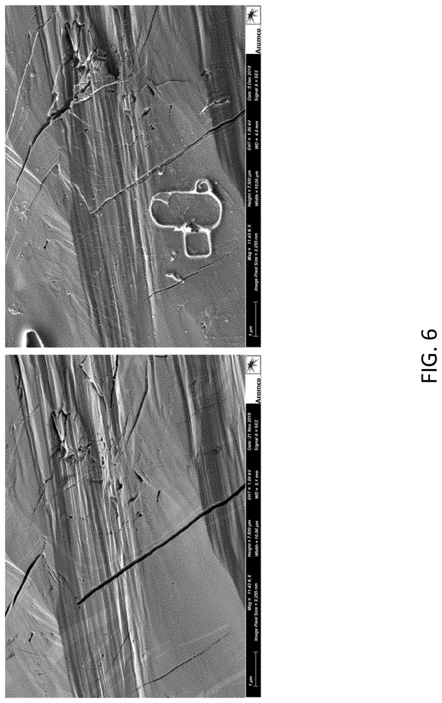
[0024] FIGS. 3-6 are scanning electron microscope (SEM) images of a sample of shale before and after treatment with bromine and supercritical carbon dioxide.
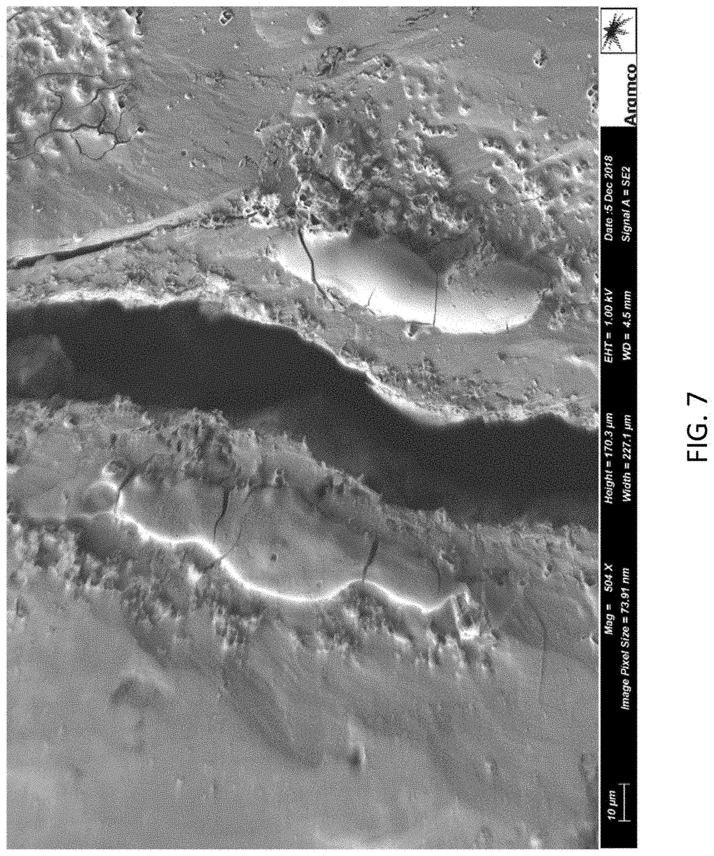
[0025] FIG. 7 is an SEM image of the shale after treatment with bromine and supercritical carbon dioxide.
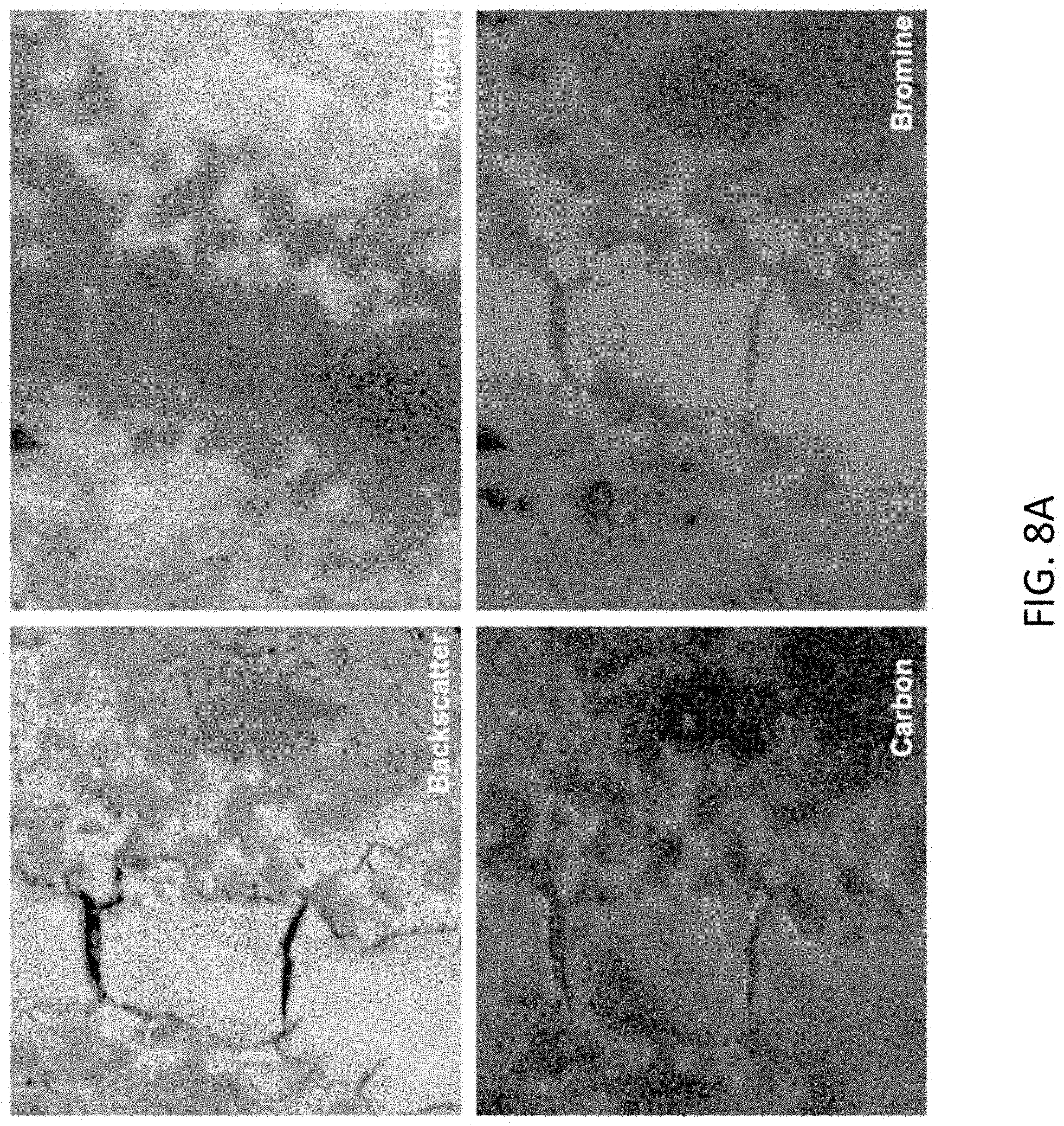
[0026] FIG. 8A is a backscatter-electron map (top left), and electron-dispersive X-Ray spectroscopic (EDS) element maps for oxygen (top right), carbon (bottom left), and bromine (bottom right).
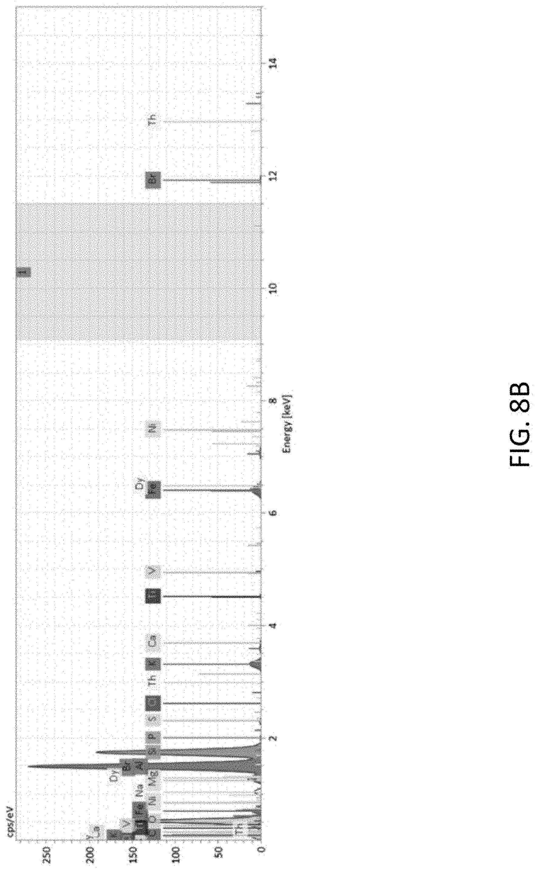
[0027] FIG. 8B is the EDS spectrum for the shale sample.
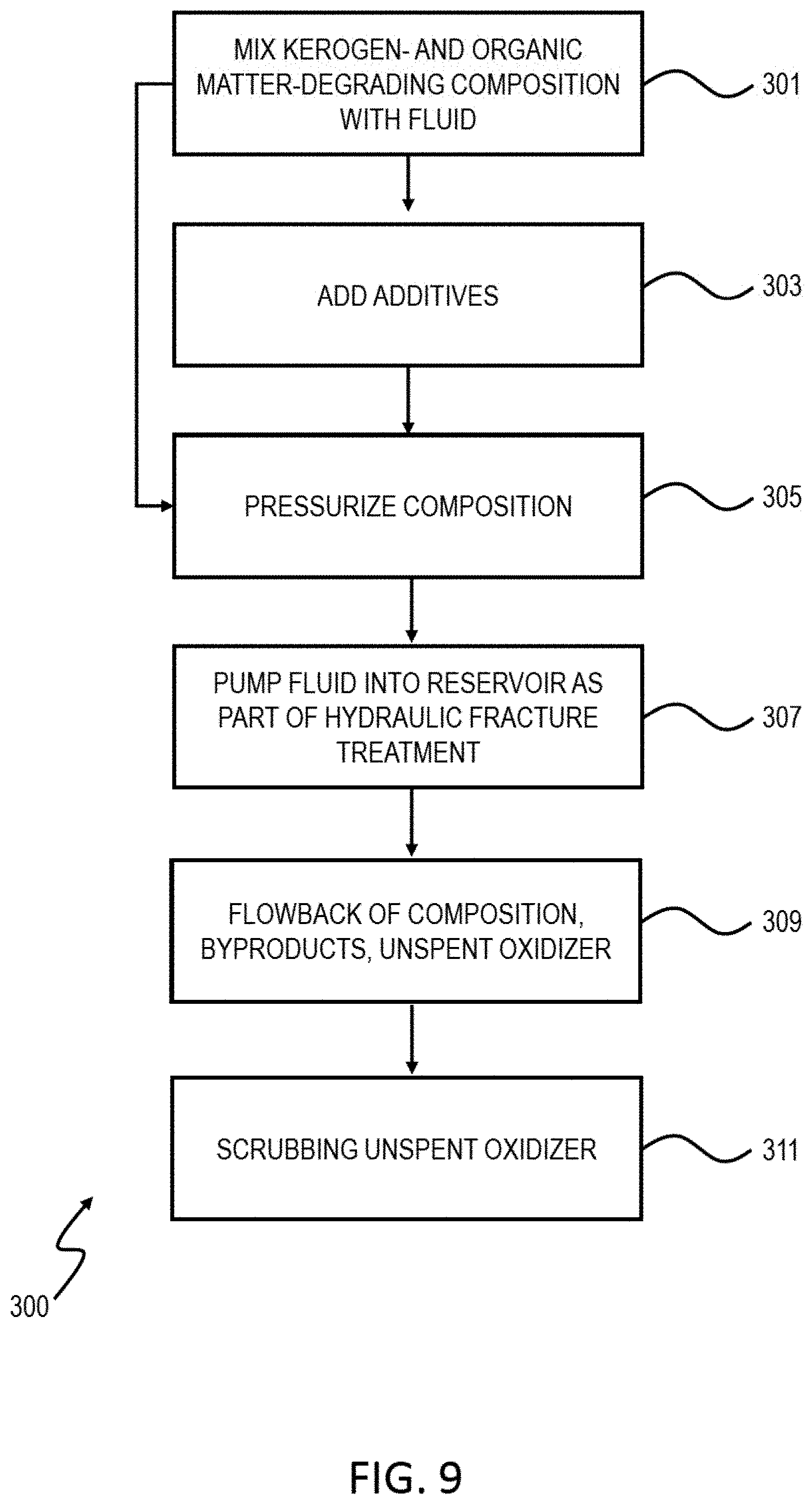
[0028] FIG. 9 is a flow chart of an example of a method for treating a well.
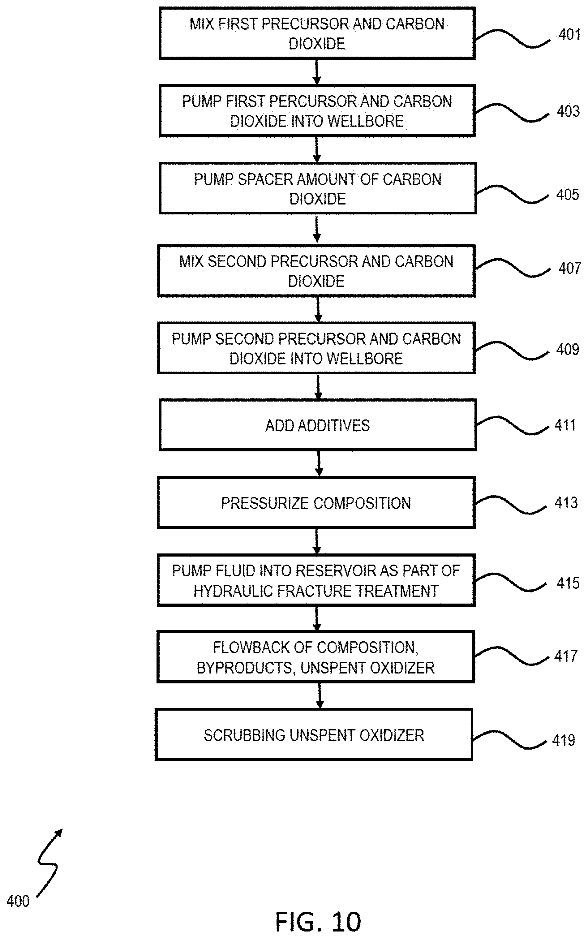
[0029] FIG. 10 is a flow chart of an example of a method for treating a well.
[0030] Like reference symbols in the various drawings indicate like elements.
DETAILED DESCRIPTION
[0031] Reference will now be made in detail to certain embodiments of the disclosed subject matter, examples of which are illustrated in part in the accompanying drawings. While the disclosed subject matter will be described in conjunction with the enumerated claims, it will be understood that the exemplified subject matter is not intended to limit the claims to the disclosed subject matter.
[0032] Provided in this disclosure, in part, are methods, compositions, and systems for degrading organic matter, for example kerogen, bitumen, or pyrobitumen, in a subterranean formation. Further, these methods, compositions, and systems allow for increased hydraulic fracturing efficiencies in subterranean formations, such as unconventional source rock reservoirs.
[0033] In some implementations, hydraulic fracturing is performed using a hydraulic fracturing fluid that includes CO.sub.2, which can be in gaseous state, in supercritical state, in liquid state or a combination of them. In order to treat and degrade kerogen present in unconventional rock sources, the fracturing fluid also includes oxidizing gasses soluble in CO.sub.2. These soluble oxidizing gasses include, but are not limited to, oxygen gas (O.sub.2), ozone (O.sub.3), fluorine gas (F.sub.2), chlorine gas (Cl.sub.2), bromine gas (Br.sub.2), chlorine monofluoride (ClF), chlorine dioxide (ClO.sub.2), nitrous oxide (N.sub.2O), nitric oxide (NO), and nitrogen dioxide (NO.sub.2). These gasses can be dissolved directly in the CO.sub.2 or generated in situ by combining chemical precursors in the fracturing fluid. For example, ozone (O.sub.3) can be generated on site from pure oxygen gas or from air. The 03 can then be injected directly into the CO.sub.2 as described later with reference to FIGS. 2A and 2B. Similarly, chlorine dioxide (ClO.sub.2) can be generated on-site with commercially available equipment, mixed with air, and added directly to the CO.sub.2 via an oxidizing gas stream as described later with reference to FIGS. 2A and 2B.
[0034] Alternatively or in addition, the oxidizing gas can be generated in situ. First, a first precursor compound is injected into the CO.sub.2, which is pumped into the wellbore. Next, a spacer amount of CO.sub.2 is pumped into the wellbore. Then, a second precursor compound is injected into the CO.sub.2, which is pumped into the wellbore. The spacer amount of CO.sub.2 ensures that the precursors do not prematurely react to form the oxidizing gas before reaching a pre-determined depth within the wellbore.
[0035] The oxidizing gasses generated in situ can be prepared by one or more of several techniques. For example, the chlorite can be combined with an acid, for example, hydrochloric acid (HCl) or hydrosulfuric acid (H.sub.2SO.sub.4). In some implementations, the in situ preparation of chlorine dioxide can occur using a chlorite and an oxidizing agent as the precursors. In some implementations, the oxidizing agent can be chlorine gas (Cl.sub.2) or hypochlorite (ClO.sup.-). The oxidizing gas can also be generated in situ using a chlorite, an oxidizing agent, and an acid. Suitable acids include citric acid, oxalic acid, HCl or H.sub.2SO.sub.4.
[0036] Alternatively, the oxidizing gas can be generated using a chlorate and a reducing agent as the precursors. Suitable reducing agents include methanol, hydrogen peroxide, HCl, or sulfur dioxide. In addition, the oxidizing gas can also be generated in situ using a chlorate, a reducing agent, and an acid. Suitable acids include HCl and H.sub.2SO.sub.4.
Example 1: Generation of Chlorine Dioxide by Oxidation of Sodium Chlorite, for Example the Reaction of Sodium Chlorite (NaClO.sub.2) and Hydrochloric Acid (HCl)
[0037] 5 NaClO.sub.2+4 HCl.fwdarw.5 NaCl+4 ClO.sub.2+2 H.sub.2O eq. 1
Example 2: Generation of Chlorine Dioxide by Oxidation of Sodium Chlorite, Using Hydrochloric Acid and Sodium Hypochlorite
[0038] 2 NaClO.sub.2+2 HCl+NaOCl.fwdarw.2 ClO.sub.2+3 NaCl+H.sub.2O eq. 2
Example 3: Generation of Chlorine Dioxide by Oxidation of Sodium Chlorite with Chlorine Gas
[0039] 2 NaClO.sub.2+Cl.sub.2.fwdarw.2 ClO.sub.2+2 NaCl eq. 3
Example 4: Generation of Chlorine Dioxide by Reduction of Sodium Chlorate, for Example, the Reduction of Sodium Chlorate with Oxalic Acid
[0040] 2 KClO.sub.3+2 H.sub.2C.sub.2O.sub.4.fwdarw.2 ClO.sub.2+2 CO.sub.2+2 H.sub.2O eq. 4
Example 5: Generation of Chlorine Dioxide by Reduction of Sodium Chlorate with Hydrochloric Acid
[0041] 2 ClO.sub.3.sup.-+2 Cl.sup.-+4 H.sup.+.fwdarw.2 ClO.sub.2+Cl.sub.2+2 H.sub.2O eq. 5
[0042] In some implementations, the fracturing fluid can include additional fracturing additives. These fracturing additives include but are not limited to proppant, viscosifiers, and breakers. Proppant types include but are not limited to sand, resin-coated sand, ceramic, resin-coated ceramic, bauxite, glass, walnut hull, resin-coated walnut hull, microproppant or nanoproppant (of sand or ceramic). The viscosifiers include but are not limited to biopolymers, synthetic polymers, fluoropolymers, and combinations thereof. The breakers include but are not limited to bromate, chlorate, chlorite, hypochlorite, persulfate, perborate, peroxide, percarbonate, nitrate, nitrite, and combinations thereof.
[0043] In some implementations, the composition can be pressurized to the breakdown pressure of the formation and injected into the wellbore. The injection pressure is then maintained for 2 to 20 hours. The composition penetrates into the source rock, where the oxidizer reacts with organic material, for example, kerogen, to form byproducts. Next, the CO.sub.2, organic material byproducts, and unspent oxidizer flow back to the surface. The organic material byproducts may be soluble in CO.sub.2 and reservoir hydrocarbons. After flowback, the unspent oxidizer can be scrubbed allowing re-use of the oxidizer. However, it is possible that all of the oxidizing gas can be consumed downhole, negating the need for disposal or flowback treatment.
[0044] The compositions described within this disclosure can be used to break down, dissolve, or remove all or parts of the kerogen or other organic material in or near the areas to be hydraulically fractured in a subterranean formation. Using a composition described within this disclosure, the kerogen or other organic matter (or both) can be broken down by, for example, pumping the composition into a subterranean formation.
[0045] The concentration of the components of the composition (for example, the oxidizers or additives) can depend on the quantity of kerogen or other organic matter in the reservoir rock. For example, the concentration of the oxidizer in the composition can be increased in response to formations with a greater quantity of organic matter to be removed or partially removed.
[0046] The composition can further include a fracturing fluid or a pad fluid and can be pumped into a subterranean formation before fracturing, during fracturing, or both. In some embodiments, the release of the composition including oxidizers can be delayed from a carrier fluid. A delayed release of the composition can decrease corrosion issues (for example, in metal tubing in the wellbore through which the fluids are delivered to the formation) and polymer degradation in the treating fluid. The polymers subject to degradation include, for example, friction reducers or other polymers used in hydraulic fracturing.
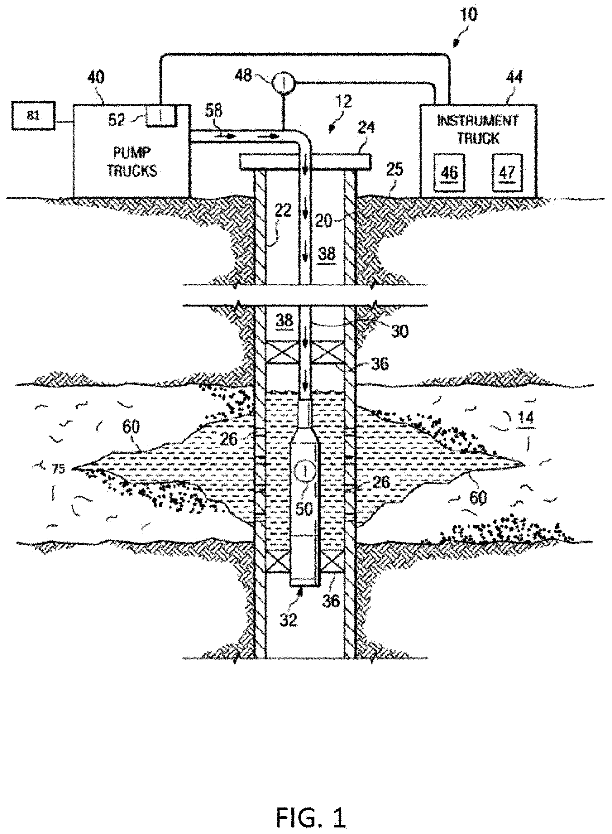
[0047] FIG. 1 illustrates an example of a fracture treatment 10 for a well 12. The well 12 can be associated with a reservoir or formation 14, for example, an unconventional reservoir in which recovery operations in addition to conventional recovery operations are practiced to recover trapped hydrocarbons. Examples of unconventional reservoirs include tight-gas sands, gas and oil shales, coalbed methane, heavy oil and tar sands, and gas-hydrate deposits. In some implementations, the formation 14 includes an underground formation of naturally fractured rock containing hydrocarbons (for example, oil, gas, or both). For example, the formation 14 can include a fractured shale. In some implementations, the well 12 can intersect other suitable types of formations 14, including reservoirs that are not naturally fractured in any significant amount.
[0048] The well 12 can include a well bore 20, casing 22 and well head 24. The well bore 20 can be a vertical or deviated bore. The casing 22 can be cemented or otherwise suitably secured in the well bore 12. Perforations 26 can be formed in the casing 22 at the level of the formation 14 to allow oil, gas, and by-products to flow into the well 12 and be produced to the surface 25. Perforations 26 can be formed using shape charges, a perforating gun or otherwise.
[0049] For the fracture treatment 10, a work string 30 can be disposed in the well bore 20. The work string 30 can be coiled tubing, sectioned pipe or other suitable tubing. A fracturing tool 32 can be coupled to an end of the work string 30. Packers 36 can seal an annulus 38 of the well bore 20 above and below the formation 14. Packers 36 can be mechanical, fluid inflatable or other suitable packers.
[0050] One or more pump trucks 40 can be coupled to the work string 30 at the surface 25. The pump trucks 40 pump fracture fluid 58 down the work string 30 to perform the fracture treatment 10 and generate the fracture 60. The fracture fluid 58 can include a fluid pad, proppants and a flush fluid. The pump trucks 40 can include mobile vehicles, equipment such as skids or other suitable structures.
[0051] One or more instrument trucks 44 can also be provided at the surface 25. The instrument truck 44 can include a fracture control system 46 and a fracture simulator 47. The fracture control system 46 monitors and controls the fracture treatment 10. The fracture control system 46 can control the pump trucks 40 and fluid valves to stop and start the fracture treatment 10 as well as to stop and start the pad phase, proppant phase and flush phase of the fracture treatment 10. The fracture control system 46 communicates with surface and subsurface instruments to monitor and control the fracture treatment 10. In some implementations, the surface and subsurface instruments may include surface sensors 48, down-hole sensors 50 and pump controls 52.
[0052] A quantity of energy applied by the fracture control system 46 to generate the fractures 60 in the reservoir or formation 14 can be affected not only by the properties of the reservoir rock in the formation but also by the organic matter (for example, kerogen 75) intertwined within the rock matrix. As discussed within this disclosure, kerogen or other organic material in a reservoir can increase the tensile strength of the rock, for example, by as much as 100-fold, resulting in a corresponding increase in the ultimate tensile strength of the rock. The rock-organic material combination has a higher modulus of toughness than rock alone. Therefore fracturing rock-organic material requires more energy than fracturing only rock. Moreover, the presence of organic material in the reservoir can affect production as well. For example, elastic properties of kerogen can prematurely close fractures resulting in decrease in production. The ductile kerogen can also enhance proppant embedment on the fracture faces which reduces fracture conductivity and long-term productivity. Accordingly, the presence of kerogen in a subterranean formation can decrease an efficiency of hydraulic fracturing treatments.
[0053] This specification describes compositions 81 to degrade the kerogen or other organic material encountered in subterranean formations, such as at the openings of cracks in hydraulic fractures. The compositions can include hydraulic fracturing fluids (for example, the fracture fluid 58) and flowed through the subterranean formation (for example, a reservoir). As or after the organic material is degraded, a quantity of energy to generate and propagate fractures in the subterranean formation (for example, a reservoir) can decrease, thereby increasing an efficiency (for example, cost, time, long-term effect) of the fracturing process. In addition, fracture length and formation surface exposure after wellbore shut-in can be greater than corresponding parameters in reservoirs in which the kerogen has not been degraded. In addition, removing or partially removing the organic matter from the near fracture zone can decrease the propensity for the fractures to close (reheal) after the pressure is released from pumping the fracturing, thereby improving the overall productivity of the well.
[0054] FIG. 2A is an example of a schematic of a gas mixing process. In some implementations, CO.sub.2 202 is flowed through a first fluid flow pathway 204 (for example, an elongate tubular member) into a mixer 206. An oxidizing gas stream 208 is flowed through a second fluid flow pathway 210 (for example, an elongate tubular member) into the mixer 206. In some implementations, the mixer 206 is operated to dissolve the oxidizing gas stream 208 in the CO.sub.2 202. The resulting mixture is flowed into a third fluid flow pathway 212 (for example, an elongate tubular member) to be injected into the wellbore (not shown).
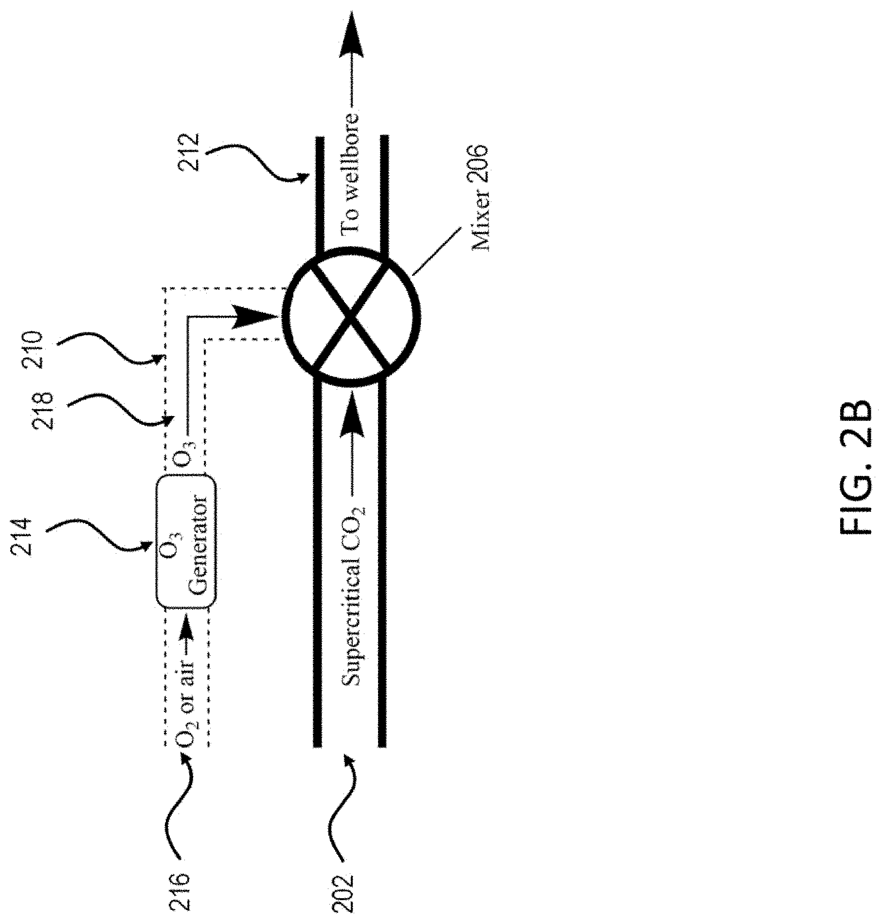
[0055] FIG. 2B is an example of a schematic of a gas mixing process. The features of FIG. 2B are substantially the same as those of FIG. 2A. In place of an oxidizing gas stream 208, an ozone generator 214 can be positioned in or otherwise fluidically coupled to the second fluid flow pathway 210. Oxygen or air 216 can be flowed into the ozone generator 214 to generate ozone 218. The generated ozone 218 can be mixed with the CO.sub.2 202 in the mixer 206. The resulting mixtures is flowed into a third fluid flow pathway 212 (for example, an elongate tubular member) to be injected into the wellbore (not shown).
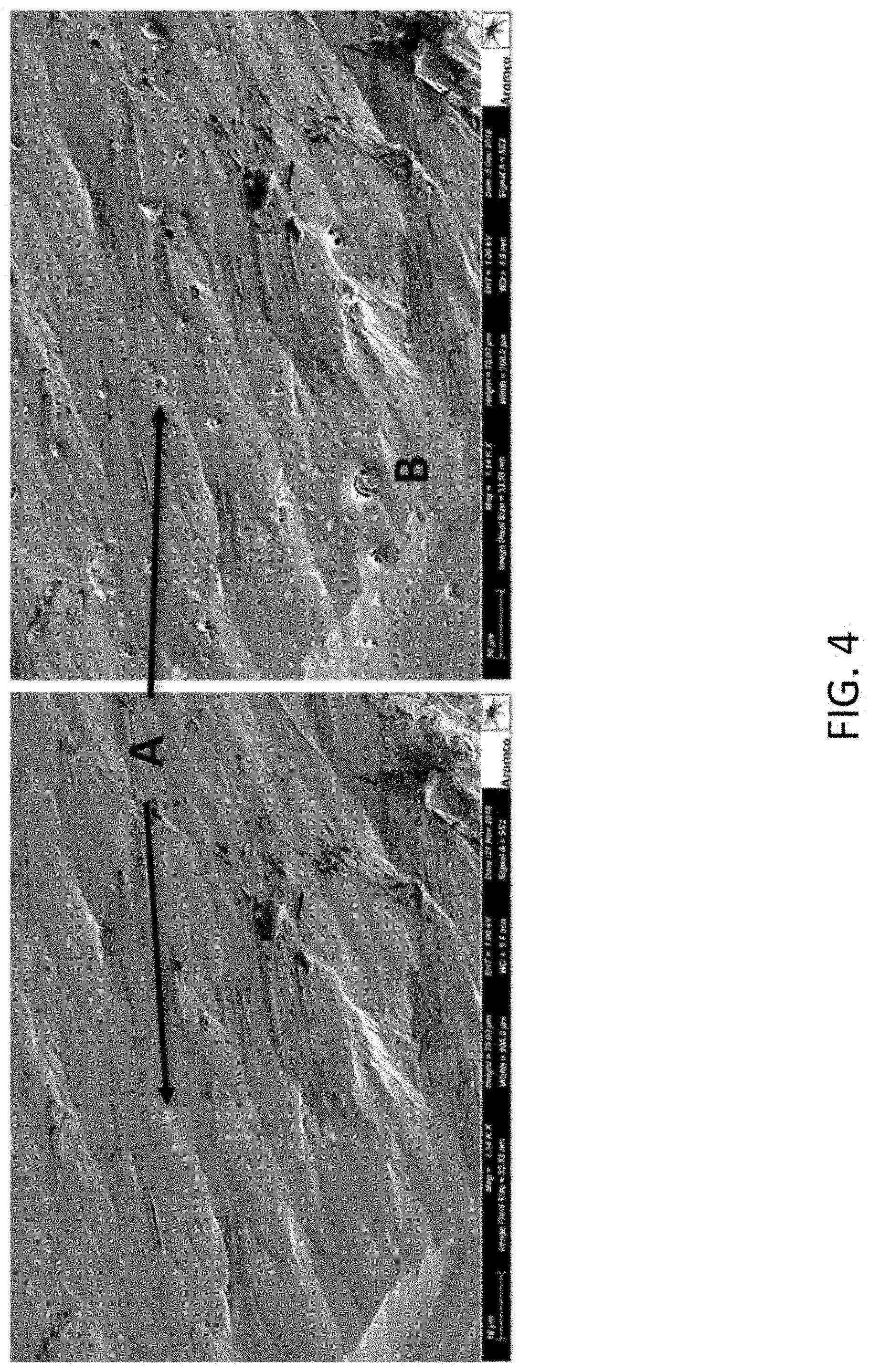
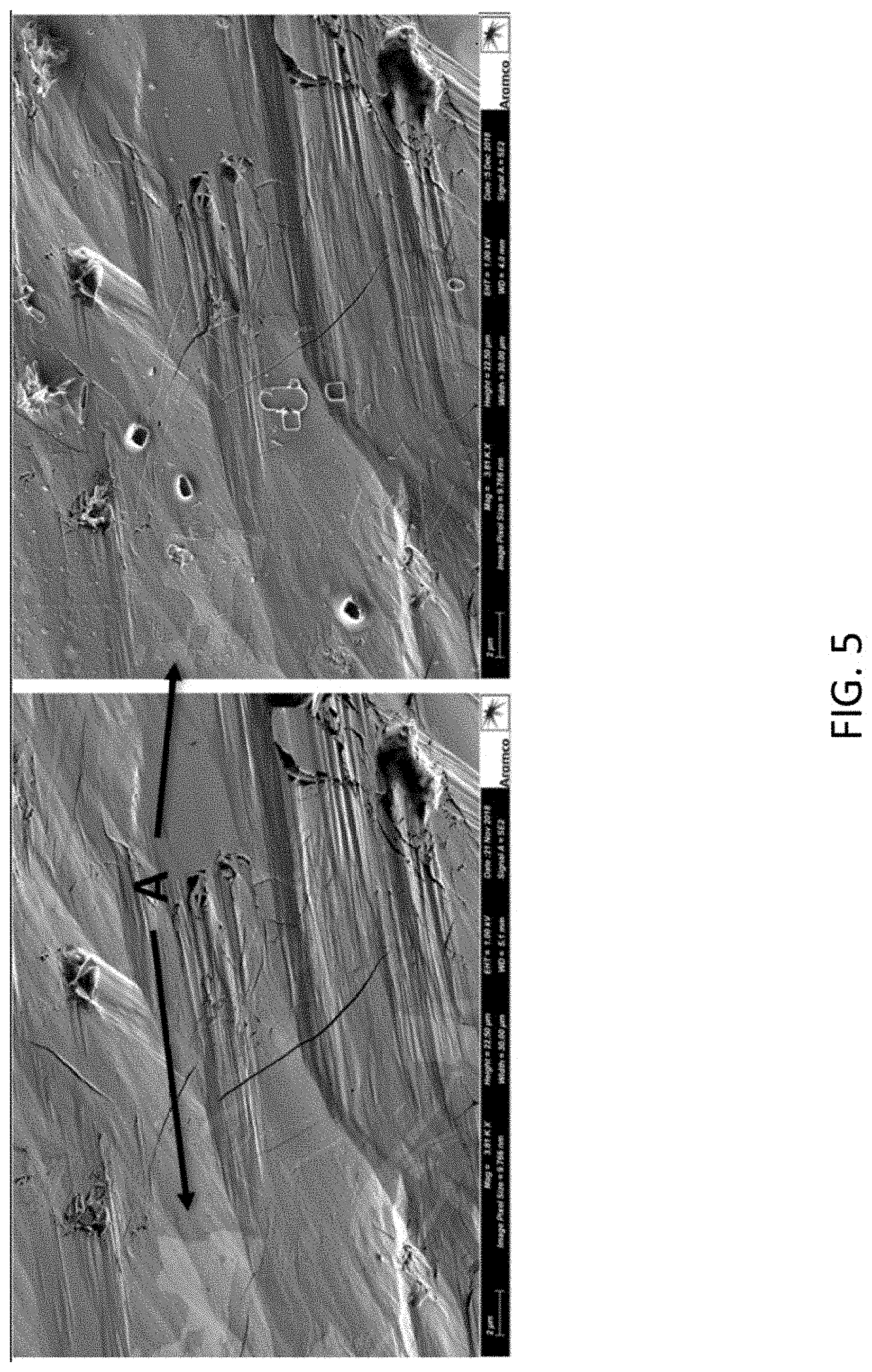
[0056] FIGS. 3-6 are scanning electron microscope (SEM) images of a sample of shale rock before (left) and after (right) treatment with bromine gas and CO.sub.2. FIG. 7 is an SEM image of the shale rock after treatment with bromine gas and CO.sub.2.
[0057] Table 1 shows mineralogy of polished shale sample before treatment.
TABLE-US-00002 TABLE 1 Mineralogy of polished shale sample before treatment Mineral Percent abundance Quartz 30 Albite 9 Orthoclase 2 Chlorite 9 Illite/Mica 35 Illite/Smectite 7 Pyrite Trace Anatase 2 Siderite 5 Kaolinite 1 Gypsum 0 Dolomite 0
[0058] The sample of the mineralogical composition was cut into a 1 cm.times.1 cm.times.1.5 cm rectangular prism and polished with a broad ion-beam to create a flat surface. Scanning electron microscope (SEM) images of the shale were obtained before treatment. The shale was then placed in a 750 mL high-pressure autoclave composed of corrosion resistant metal alloy. Next, 3 mL of bromine (60 mmol) was added to the autoclave. The autoclave was then filled with liquid carbon dioxide (CO.sub.2) at 800 psi. The autoclave was then sealed and heated to 150.degree. C. at a pressure of 2600 psi for 20 hours. The autoclave was then allowed to cool and depressurize. The sample was then washed with 10 mL of deionized water to remove sodium bromide (NaBr) salt crystals from the surface of the rock. Next, SEM images were obtained after treatment and compared to images taken before treatment (FIGS. 3-6). In the treated sample, sites formerly occupied by NaBr crystals are seen in halos of brominated kerogen tar (FIG. 5 right; FIG. 6 right). The presence of NaBr is attributable to trace water in the system and interfacial condensation of water at the rock surface upon depressurization. In the treated sample, brominated kerogen tar was found to have upwelled in fissures in the shale (FIG. 3, B; FIG. 5 right) and spatter of brominated kerogen tar is observed around fissures generated through the treatment process (FIG. 4, B; FIG. 7). In the treated sample, brominated kerogen tar is also visible on the surface of the treated sample (FIG. 8A). In addition, pyrite and iron-containing rock was observed to have been dissolved away from the shale (FIG. 3, A; FIG. 4, A; FIG. 5, A).
[0059] FIG. 8A is a backscatter-electron map (top left), and electron-dispersive X-Ray spectroscopic (EDS) element maps for oxygen (top right), carbon (bottom left), and bromine (bottom right). FIG. 8B is the EDS spectrum for the sample (bottom), which confirms the presence of bromine.
[0060] FIG. 9 is a flowchart of an example of a process 300 for degrading organic material in a subterranean zone. The process can be implemented using different types of hydraulic fracturing fluids. At 301, an organic matter-degrading composition (for example, a composition including an oxidizer, such as chlorine dioxide) is mixed with a fluid. The fluid can be a hydraulic fracture fluid or a pad fluid that is flowed into the reservoir before the hydraulic fracture fluid (or both). At 303, additives, including friction reducers, viscosifiers, breakers, proppant, scale inhibitors, clay swelling inhibitors, corrosion inhibitors, iron control agents, flowback aid, or biocides, can be added to the mixture of the composition and fluid. At 305, the composition is pressurized. At 307, the fluid (with the organic matter-degrading composition) is pumped into the reservoir as part of a hydraulic fracture treatment. As described previously, the organic matter degrades upon reacting with the composition. At 309, the composition, byproducts, and unspent oxidizer flowback to the surface. At 311, unspent oxidizer may be scrubbed for re-use.
[0061] FIG. 10 is a flowchart of an example of a process 400 for degrading organic material in a subterranean zone. The process can be implemented using different types of hydraulic fracturing fluids. This process 400 includes the use of precursors to generate the oxidizing gas in situ. At 401, a first precursor is mixed with carbon dioxide. At 403, the first precursor and carbon dioxide are pumped into the wellbore. At 405, a spacer amount of carbon dioxide is pumped into the wellbore. At 407, a second precursor is mixed with carbon dioxide. At 409, the second precursor and carbon dioxide are pumped into the wellbore. At 411, additives, including friction reducers, viscosifiers, breakers, proppant, scale inhibitors, clay swelling inhibitors, corrosion inhibitors, iron control agents, flowback aid, or biocides, can be added to the mixture or fluid. At 413, the composition is pressurized. At 415, the composition is pumped into the reservoir as part of a hydraulic fracture treatment. As described previously, the precursors react to generate an oxidizing gas in situ. The kerogen and organic matter degrade upon reacting with the composition containing the in situ generated gas. At 417, the composition, byproducts, and unsepent oxidizer flowback to the surface. At 419, unspent oxidizer may be scrubbed for re-use.
[0062] The term "about" as used in this disclosure can allow for a degree of variability in a value or range, for example, within 10%, within 5%, or within 1% of a stated value or of a stated limit of a range.
[0063] The term "substantially" as used in this disclosure refers to a majority of, or mostly, as in at least about 50%, 60%, 70%, 80%, 90%, 95%, 96%, 97%, 98%, 99%, 99.5%, 99.9%, 99.99%, or at least about 99.999% or more.
[0064] The term "solvent" as used in this disclosure refers to a liquid that can dissolve a solid, another liquid, or a gas to form a solution. Non-limiting examples of solvents are silicones, organic compounds, water, alcohols, ionic liquids, and supercritical fluids.
[0065] The term "room temperature" as used in this disclosure refers to a temperature of about 15 degrees Celsius (.degree. C.) to about 28.degree. C.
[0066] The term "downhole" as used in this disclosure refers to under the surface of the earth, such as a location within or fluidly connected to a wellbore.
[0067] As used in this disclosure, the term "fracturing fluid" refers to fluids or slurries used downhole during fracturing operations.
[0068] As used in this disclosure, the term "fluid" refers to liquids and gels, unless otherwise indicated.
[0069] As used in this disclosure, the term "subterranean material" or "subterranean zone" refers to any material under the surface of the earth, including under the surface of the bottom of the ocean. For example, a subterranean zone or material can be any section of a wellbore and any section of a subterranean petroleum- or water-producing formation or region in fluid contact with the wellbore. Placing a material in a subterranean zone can include contacting the material with any section of a wellbore or with any subterranean region in fluid contact with the material. Subterranean materials can include any materials placed into the wellbore such as cement, drill shafts, liners, tubing, casing, or screens; placing a material in a subterranean zone can include contacting with such subterranean materials. In some examples, a subterranean zone or material can be any downhole region that can produce liquid or gaseous petroleum materials, water, or any downhole section in fluid contact with liquid or gaseous petroleum materials, or water. For example, a subterranean zone or material can be at least one of an area desired to be fractured, a fracture or an area surrounding a fracture, and a flow pathway or an area surrounding a flow pathway, in which a fracture or a flow pathway can be optionally fluidly connected to a subterranean petroleum- or water-producing region, directly or through one or more fractures or flow pathways.
[0070] As used in this disclosure, "treatment of a subterranean zone" can include any activity directed to extraction of water or petroleum materials from a subterranean petroleum- or water-producing formation or region, for example, including drilling, stimulation, hydraulic fracturing, clean-up, acidizing, completion, cementing, remedial treatment, abandonment, aquifer remediation, identifying oil rich regions via imaging techniques, and the like.
[0071] A number of implementations of the disclosure have been described. Nevertheless, it will be understood that various modifications may be made without departing from the spirit and scope of the disclosure.
* * * * *
D00000
D00001
D00002
D00003
D00004
D00005
D00006
D00007
D00008
D00009
D00010
D00011
D00012
XML
uspto.report is an independent third-party trademark research tool that is not affiliated, endorsed, or sponsored by the United States Patent and Trademark Office (USPTO) or any other governmental organization. The information provided by uspto.report is based on publicly available data at the time of writing and is intended for informational purposes only.
While we strive to provide accurate and up-to-date information, we do not guarantee the accuracy, completeness, reliability, or suitability of the information displayed on this site. The use of this site is at your own risk. Any reliance you place on such information is therefore strictly at your own risk.
All official trademark data, including owner information, should be verified by visiting the official USPTO website at www.uspto.gov. This site is not intended to replace professional legal advice and should not be used as a substitute for consulting with a legal professional who is knowledgeable about trademark law.