Loading Tray With Adjustable Capacity For Carrying Articles Of Different Sizes
WANG; HUI ; et al.
U.S. patent application number 16/585785 was filed with the patent office on 2021-01-28 for loading tray with adjustable capacity for carrying articles of different sizes. The applicant listed for this patent is TRIPLE WIN TECHNOLOGY(SHENZHEN) CO.LTD.. Invention is credited to XIAO-LING TANG, HUI WANG.
| Application Number | 20210024252 16/585785 |
| Document ID | / |
| Family ID | 1000004395431 |
| Filed Date | 2021-01-28 |


| United States Patent Application | 20210024252 |
| Kind Code | A1 |
| WANG; HUI ; et al. | January 28, 2021 |
LOADING TRAY WITH ADJUSTABLE CAPACITY FOR CARRYING ARTICLES OF DIFFERENT SIZES
Abstract
One type of tray adaptable to carry articles of different sizes includes a substrate, at least one blocking member, and at least one positioning block. The substrate includes a peripheral region and a middle region within. The blocking member is disposed on the peripheral region of the substrate, and the positioning block is detachably disposed on an inner side of the blocking member facing the middle portion.
| Inventors: | WANG; HUI; (Shenzhen, CN) ; TANG; XIAO-LING; (Shenzhen, CN) | ||||||||||
| Applicant: |
|
||||||||||
|---|---|---|---|---|---|---|---|---|---|---|---|
| Family ID: | 1000004395431 | ||||||||||
| Appl. No.: | 16/585785 | ||||||||||
| Filed: | September 27, 2019 |
| Current U.S. Class: | 1/1 |
| Current CPC Class: | B65D 25/10 20130101 |
| International Class: | B65D 25/10 20060101 B65D025/10 |
Foreign Application Data
| Date | Code | Application Number |
|---|---|---|
| Jul 26, 2019 | CN | 201921202160.9 |
Claims
1. A tray comprising a substrate, at least one blocking member, and at least one positioning block, the substrate comprising a peripheral region and a middle region surrounded by the peripheral region, the blocking member is disposed on the peripheral region of the substrate, and the positioning block is detachably disposed on an inner side of the blocking member facing the middle portion.
2. The tray according to claim 1, wherein the blocking member is detachably disposed on the substrate.
3. The tray according to claim 2, wherein the substrate defines at least one first hole, and the blocking member defines at least one second hole corresponding to one or more of the at least one first hole, the blocking member is detachably disposed on the substrate by receiving at least one first tip post in the at least one second hole and the corresponding first holes.
4. The tray according to claim 3, wherein the positioning block defines at least one third hole corresponding to one or more of the first holes, and the positioning block is detachably disposed on the substrate by receiving at least one second tip post in the at least one third hole and the corresponding first holes.
5. The tray according to claim 4, wherein a number of the first holes is equal to or more than a sum of the second holes and the third holes.
6. The tray according to claim 1, wherein the positioning block is magnetically attracted to the substrate by a magnet.
7. The tray according to claim 1, wherein the at least one blocking member is integrally formed with the substrate.
8. The tray according to claim 1, wherein the at least one blocking member comprises three blocking members, the peripheral region comprises a first side portion, a second side portion and a third side portion, the three blocking members are disposed on the first side portion, the second side portion and the third side portion respectively.
9. The tray according to claim 8, wherein the peripheral region further comprises a fourth side portion, the first side portion and the third side portion are connected between the second side portion and the fourth side portion, and the second side portion and the fourth side portion are connected between the first side portion and the third side portion, the at least one positioning block comprises a positioning block disposed on the fourth side portion.
10. The tray according to claim 1, further comprising at least one elastic member disposed on each of the at least one positioning block, the elastic member is configured to provide protections to an article on the substrate from impact forces.
Description
FIELD
[0001] The subject matter herein generally relates to materials handling in manufacture processes.
BACKGROUND
[0002] Existing loading trays are generally of fixed sizes and can be used for loading products of one size. Existing loading trays generally cannot be shared by products of different sizes. That is, a loading tray suitable for a product of a first size is not suitable for a product of a second size. When products of different sizes need to be transported, trays with different sizes are required. Exchanging the loading trays of different sizes may be time consuming, laborious, and expensive.
[0003] Therefore, there is room for improvement.
BRIEF DESCRIPTION OF THE DRAWINGS
[0004] Implementations of the present technology will now be described, by way of embodiments, with reference to the attached figures.
[0005] FIG. 1 is an isometric view of a tray according to a first embodiment of the present disclosure.
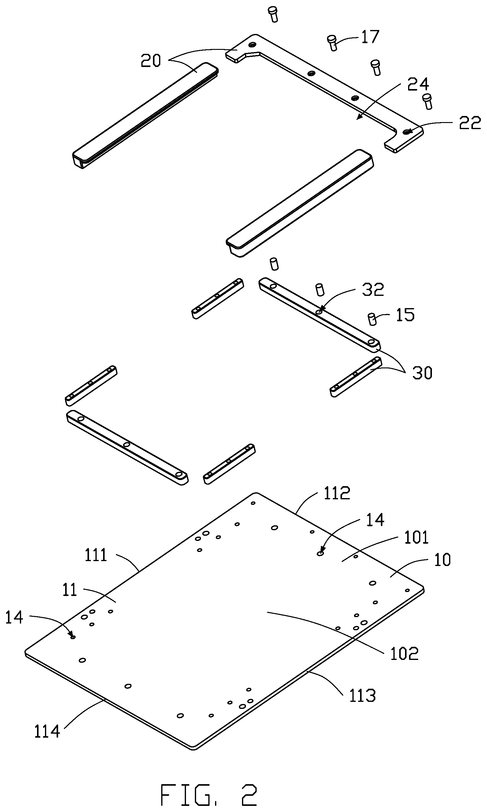
[0006] FIG. 2 is an exploded view of the tray of FIG. 1.
[0007] FIG. 3 is an isometric view of a tray according to a second embodiment of the present disclosure.
[0008] FIG. 4 is an isometric view of a tray according to a third embodiment of the present disclosure.
[0009] FIG. 5 is an isometric view of a tray according to a fourth embodiment of the present disclosure.
[0010] FIG. 6 is a plan view of an elongated positioning block in the tray according to any one of the above embodiments.
[0011] FIG. 7 is a top plan view of an "L-shaped" positioning block in the tray according to any one of the above embodiments.
[0012] FIG. 8 is a top plan view of a "Z-shaped" positioning block in the tray according to any one of the above embodiments.
DETAILED DESCRIPTION
[0013] The present disclosure is made in conjunction with the accompanying drawings. Specific embodiments of the present disclosure are described.
[0014] In the following description, when an element is described as being "fixed to" another element, the element can be fixed to the another element with or without intermediate elements. When an element is described as "connecting" another element, the element can be connected to the other element with or without intermediate elements.
[0015] Without a given definition otherwise, all terms used have the same meaning as commonly understood by those skilled in the art. The term "and/or" means including any and all combinations of one or more of associated listed items.
[0016] Referring to FIG. 1 and FIG. 2, the present disclosure provides a tray 100 which includes a substrate 10, a plurality of blocking members 20, and a plurality of positioning blocks 30. The tray 100 is configured for carrying articles and holding the articles in place to prevent the articles from moving relative to the tray 100 during transporting.
[0017] In the embodiment, the substrate 10 is substantially a rectangular plate. The substrate 10 has a first surface 11 and a second surface 12 opposite to the first surface 11, the first surface 11 is configured to carry articles.
[0018] A plurality of first holes 14 are defined in the substrate 10, The first holes 14 extend perpendicularly through the first surface 11 and the second surface 12. The first holes 14 can accept a plurality of first tip posts 17 and/or a plurality of second tip posts 15. The first tip posts 17 are configured to secure the blocking member 20 and/or the positioning block 30.
[0019] In the embodiment, the first holes 14 are of a same size. In alternative embodiments, the first holes 14 are of different sizes where the first tip posts 17 and the second tip posts 15 are of different sizes.
[0020] In an alternative embodiment, the blocking members 20 and/or the positioning blocks 30 can be screwed to the substrate 10 by screws.
[0021] In an alternative embodiment, magnetic components 16 can be used to fix the positioning block 30 to the substrate 10.
[0022] Referring to FIG. 3, in a second embodiment, the substrate 10 defines one or more holes 13 to reduce a weight of the tray 100. The holes 13 also facilitate the removal of residues from the articles.
[0023] Referring to FIG. 1 and FIG. 2, the substrate 10 includes a peripheral region 101 and a middle region 102 surrounded by the peripheral region 101 on the first surface 11. The blocking members 20 are disposed on the peripheral region 101, The peripheral region 101 includes a first side portion 111, a second side portion 112, a third side portion 113, and a fourth side portion 114. The first side portion 111, the second side portion 112, the third portion 113, and the fourth side portion 114 are connected end-to-end. The first side portion 111 and the third side portion 113 are connected between the second side portion 112 and the fourth side portion 114, and the second side portion 112 and the fourth side portion 114 are connected between the first side portion 111 and the third side portion 113. The first side portion 111 is opposite to the third side portion 113 and the second side portion 112 is opposite to the fourth side portion 114. The first side portion 111, the second side portion 112, and the third side portion 113 can support blocking members 20. Each of the blocking members 20 is in parallel with an edge of the substrate 10 where the supporting side portion 111, 112, or 113 is located. The blocking members 20 disposed on the first side portion 111 and the third side portion 113 are straight strips, and the blocking member 20 disposed on the second side portion 112 is a curved strip with two ends bent toward a same side of the blocking member 20, thus a groove 24 is defined between the ends of the blocking member 20. An article can be moved onto and off the substrate 10 through the fourth side portion 114.
[0024] The blocking members 20 are detachably disposed on the substrate 10. In the embodiment, the blocking members 20 define a plurality of second holes 22 that penetrate the blocking members 20. The second holes 22 are aligned with the first holes 14. The blocking members 20 can be fixed to the substrate 10 by inserting the first tip posts 17 in the first holes 14 and the second holes 22. The blocking members 20 block any movement and sliding of an article on the tray 100 during transportation, and prevent the articles from colliding with other objects from some directions, thus reducing damage to the article. The blocking members 20 can further prevent movement and slippage of the positioning blocks 30.
[0025] In an alternative embodiment, the blocking members 20 are non-detachably fixed on the first surface 11 of the substrate 10. For example, referring to FIG. 4, the blocking members 20 can be integrally formed with the substrate 10. The blocking members 20 are spaced apart from each other. Referring to FIG. 5, the blocking members 20 are connected to each other.
[0026] The positioning blocks 30 are detachably disposed on the substrate 10. In the embodiment, each of the positioning block 30 defines at least one third hole 32. The third holes 32 penetrates the positioning blocks 30, and are aligned with the first holes 14. The positioning blocks 30 are fixed on the substrate 10 by inserting the second tip posts 15 in the third holes 32 and the first holes 14.
[0027] The number of the first holes 14 is equal to or more than the sum of the second holes 22 and the third holes 32. More first holes 14 improve the utility and universality of the tray 100, so that the tray 100 can suit more articles of different sizes. When the tray 100 is used to carry articles of different sizes, the positions of the blocking members 20 and the positioning blocks 30 can be varied, thereby an area for carrying the articles is changed and adapted to the size of the current article.
[0028] In an embodiment, the positioning block 30 is basically made of an aluminum alloy. The positioning block 30 is attracted on the substrate 10 by the magnet 16, and the position of the positioning block 30 can be conveniently set. In addition, one or more positioning blocks 30 can be disposed on the substrate 10. When more than one positioning blocks 30 are disposed on the substrate 10, the changes in respective positions of the positioning blocks 30 enables articles of smaller or larger size to be accommodated. Furthermore, positioning blocks 30 not immediately required can be moved to another portion of the substrate 10 such as the peripheral, so that an article of larger size can be placed on the substrate 10. The positioning blocks 30 are attracted to the substrate 10 and magnetism prevents the loss of the positioning blocks 30.
[0029] In an alternative embodiment, the positioning blocks 30 are fixed to the substrate 10 by magnetic attraction in addition to friction fitting when the second tip posts 15 are inserted in the third holes 32 and the first holes 14.
[0030] Furthermore, the positioning blocks 30 can be of various sizes and shapes. For example, referring to FIGS. 6-8, each of the positioning blocks 30 can be a straight strip, an "L-shaped" strip, or a "Z-shaped" strip.
[0031] In the embodiment, the positioning blocks 30 are straight strips of two sizes. A positioning block 30 is respectively disposed on the first side portion 111, the second side portion 112, the third side portion 113, and the fourth side portion 114. The positioning blocks 30 on the first side portion 111, the second side portion 112, and the third side portion 113 are adjacent to the blocking members 20, and the positioning block 30 on the fourth side portion 114 is parallel to the blocking member 20 of the second side portion 112.
[0032] Referring to FIG. 6, an elastic member 34 may be disposed on each of the positioning blocks 30, so as to face the article on the substrate 10. The elastic member 34 offers shockproofing to prevent the article in the substrate 10 from being damaged.
[0033] The tray 100 provided by the present disclosure can be used for transporting articles of different sizes by adjusting positions of the positioning blocks 30, thereby realizing the sharing of one standard type of tray 100 between articles of different sizes, which saves cost as well as labor.
[0034] The embodiments shown and described above are only examples. Even though numerous characteristics and advantages of the present technology have been set forth in the foregoing description, together with details of the structure and function of the present disclosure, the disclosure is illustrative only, and changes can be made in the detail, including in matters of shape, size, and arrangement of the parts within the principles of the present disclosure, up to and including the full extent established by the broad general meaning of the terms used in the claims.
* * * * *
D00000
D00001
D00002
D00003
D00004
D00005
D00006
D00007
D00008
XML
uspto.report is an independent third-party trademark research tool that is not affiliated, endorsed, or sponsored by the United States Patent and Trademark Office (USPTO) or any other governmental organization. The information provided by uspto.report is based on publicly available data at the time of writing and is intended for informational purposes only.
While we strive to provide accurate and up-to-date information, we do not guarantee the accuracy, completeness, reliability, or suitability of the information displayed on this site. The use of this site is at your own risk. Any reliance you place on such information is therefore strictly at your own risk.
All official trademark data, including owner information, should be verified by visiting the official USPTO website at www.uspto.gov. This site is not intended to replace professional legal advice and should not be used as a substitute for consulting with a legal professional who is knowledgeable about trademark law.