Front Body Structure Of Vehicle
KIM; Do Hoi ; et al.
U.S. patent application number 16/689331 was filed with the patent office on 2021-01-28 for front body structure of vehicle. This patent application is currently assigned to HYUNDAI MOTOR COMPANY. The applicant listed for this patent is HYUNDAI MOTOR COMPANY, KIA MOTORS CORPORATION. Invention is credited to Do Hoi KIM, Jai Hak KIM.
| Application Number | 20210024133 16/689331 |
| Document ID | / |
| Family ID | 1000004498657 |
| Filed Date | 2021-01-28 |


| United States Patent Application | 20210024133 |
| Kind Code | A1 |
| KIM; Do Hoi ; et al. | January 28, 2021 |
FRONT BODY STRUCTURE OF VEHICLE
Abstract
A front body structure of a vehicle includes: a closed loop member projected on a front surface of a body to form a closed loop such that both sides of the closed loop are coupled to front ends of front side members at both sides of the body, a back beam assembly coupled to a front part of the closed loop member, and lower reinforcement members connecting a lower portion of the closed loop member, at both sides thereof, to a front part of a subframe.
| Inventors: | KIM; Do Hoi; (Seoul, KR) ; KIM; Jai Hak; (Gunpo-si, KR) | ||||||||||
| Applicant: |
|
||||||||||
|---|---|---|---|---|---|---|---|---|---|---|---|
| Assignee: | HYUNDAI MOTOR COMPANY Seoul KR KIA MOTORS CORPORATION Seoul KR |
||||||||||
| Family ID: | 1000004498657 | ||||||||||
| Appl. No.: | 16/689331 | ||||||||||
| Filed: | November 20, 2019 |
| Current U.S. Class: | 1/1 |
| Current CPC Class: | B62D 21/03 20130101; B62D 21/155 20130101; B62D 21/08 20130101 |
| International Class: | B62D 21/03 20060101 B62D021/03; B62D 21/15 20060101 B62D021/15; B62D 21/08 20060101 B62D021/08 |
Foreign Application Data
| Date | Code | Application Number |
|---|---|---|
| Jul 24, 2019 | KR | 10-2019-0089884 |
Claims
1. A front body structure of a vehicle, comprising: a closed loop member projected on a front surface of a body and configured to form a closed loop such that both sides of the closed loop are coupled to front ends of front side members at both sides of the body; a back beam assembly coupled to a front part of the closed loop member; and lower reinforcement members connecting a lower portion of the closed loop member, at both sides thereof, to a front part of a subframe.
2. The front body structure according to claim 1, wherein the closed loop member is a front end module carrier.
3. The front body structure according to claim 1, wherein the back beam assembly comprises: back beam support members coupled to respective front parts of both sides of the closed loop member; and a back beam coupled to a front part of the back beam support members while extending in a transverse direction of the body.
4. The front body structure according to claim 3, wherein the back beam support members are installed to be rectilinearly aligned with the front side members in a forward and rearward direction of the body with the closed loop member interposed therebetween.
5. The front body structure according to claim 1, wherein the lower portion of the closed loop member has a cap-type cross-sectional structure that is open toward a rear of the body.
6. The front body structure according to claim 1, wherein the lower portion of the closed loop member is provided with a reinforcement insert extending in a transverse direction of the body.
7. The front body structure according to claim 6, wherein the lower reinforcement members are coupled to a rear part of the reinforcement insert to connect the rear of the reinforcement insert to the subframe.
8. The front body structure according to claim 1, wherein each of the lower reinforcement members is configured by coupling an inner panel inside the body to an outer panel outside the body with a closed space defined therebetween, and has a polyprism shape that extends in a forward and rearward direction of the body.
9. The front body structure according to claim 8, wherein a plurality of shock absorbing beads are arranged in a front of the inner panel and outer panel of the lower reinforcement members in a longitudinal direction of the lower reinforcement members.
10. The front body structure according to claim 8, wherein a rear end of the lower reinforcement members has a cross-sectional structure that is opened to enlarge an area coupled to the front part of the subframe.
11. The front body structure according to claim 1, wherein the closed loop member, the front side members, the subframe, and the lower reinforcement members are connected in turn such that a shape thereof projected in a lateral direction of the body forms a closed curve therein.
Description
CROSS REFERENCE TO RELATED APPLICATION
[0001] This application claims priority to and the benefit of Korean Patent Application No. 10-2019-0089884, filed on Jul. 24, 2019, the entire contents of which are incorporated herein by reference.
FIELD
[0002] The present disclosure relates to a front body structure of a vehicle.
BACKGROUND
[0003] The statements in this section merely provide background information related to the present disclosure and may not constitute prior art.
[0004] An electric vehicle tends to have a relatively short overhang as no engine is mounted in the front of its body corresponding to the engine compartment of a conventional vehicle equipped with an internal combustion engine. Especially, a very small electric vehicle tends to have a very short overhang.
[0005] As described above, the very short overhang of the body is advantageous in reducing the weight of the vehicle, but it means that, in the event of vehicle collision, the space to absorb shocks is relatively reduced due to deformation, resulting in a considerable reduction in the collision safety of the vehicle.
[0006] The foregoing is intended merely to aid in the understanding of the background of the present disclosure, and is not intended to mean that the present disclosure falls within the purview of the related art that is already known to those skilled in the art.
SUMMARY
[0007] The present disclosure proposes a front body structure of a vehicle, capable of improving collision performance of a vehicle by effectively distributing and absorbing collision loads due to the forward collision of the vehicle, while having a short overhang as in a very small electric vehicle or the like.
[0008] In accordance with an aspect of the present disclosure, a front body structure of a vehicle includes: a closed loop member projected on a front surface of a body to form a closed loop such that both sides of the closed loop are coupled to front ends of front side members at both sides of the body, a back beam assembly coupled to a front part of the closed loop member, and lower reinforcement members connecting a lower portion of the closed loop member, at both sides thereof, to a front part of a subframe.
[0009] The closed loop member may be a front end module carrier.
[0010] The back beam assembly may include back beam support members coupled to respective front parts of both sides of the closed loop member, and a back beam coupled to a front part of the back beam support members while extending in a transverse direction of the body.
[0011] The back beam support members may be installed to be rectilinearly aligned with the front side members in a forward and rearward direction of the body with the closed loop member interposed therebetween.
[0012] The lower portion of the closed loop member may have a cap-type cross-sectional structure that is open toward a rear of the body.
[0013] The lower portion of the closed loop member may be provided with a steel reinforcement insert extending in a transverse direction of the body.
[0014] The lower reinforcement members may be coupled to the rear of the reinforcement insert to connect a rear part of the reinforcement insert to the subframe.
[0015] Each of the lower reinforcement members may be configured by coupling an inner panel inside the body to an outer panel outside the body with a closed space defined therebetween, and have a polyprism shape that extends in a forward and rearward direction of the body.
[0016] A plurality of shock absorbing beads may be arranged in the front of the inner panel and outer panel of the lower reinforcement members in a longitudinal direction of the lower reinforcement members.
[0017] The rear end of the lower reinforcement members may have a cross-sectional structure that is opened to enlarge an area coupled to the front part of the subframe.
[0018] The closed loop member, the front side members, the subframe, and the lower reinforcement members may be connected in turn such that the shape thereof projected in a lateral direction of the body forms a closed curve therein.
[0019] As apparent from the above description, the present disclosure can maximize the collision performance of the vehicle by effectively distributing and absorbing the collision loads due to the forward collision of the vehicle, while allowing the body of the vehicle to have a short overhang structure as in the very small electric vehicle or the like.
[0020] Further areas of applicability will become apparent from the description provided herein. It should be understood that the description and specific examples are intended for purposes of illustration only and are not intended to limit the scope of the present disclosure.
DRAWINGS
[0021] In order that the disclosure may be well understood, there will now be described various forms thereof, given by way of example, reference being made to the accompanying drawings, in which:
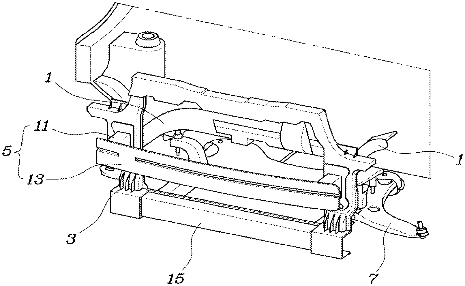
[0022] FIG. 1 is a view illustrating a front body structure of a vehicle according to one form of the present disclosure;
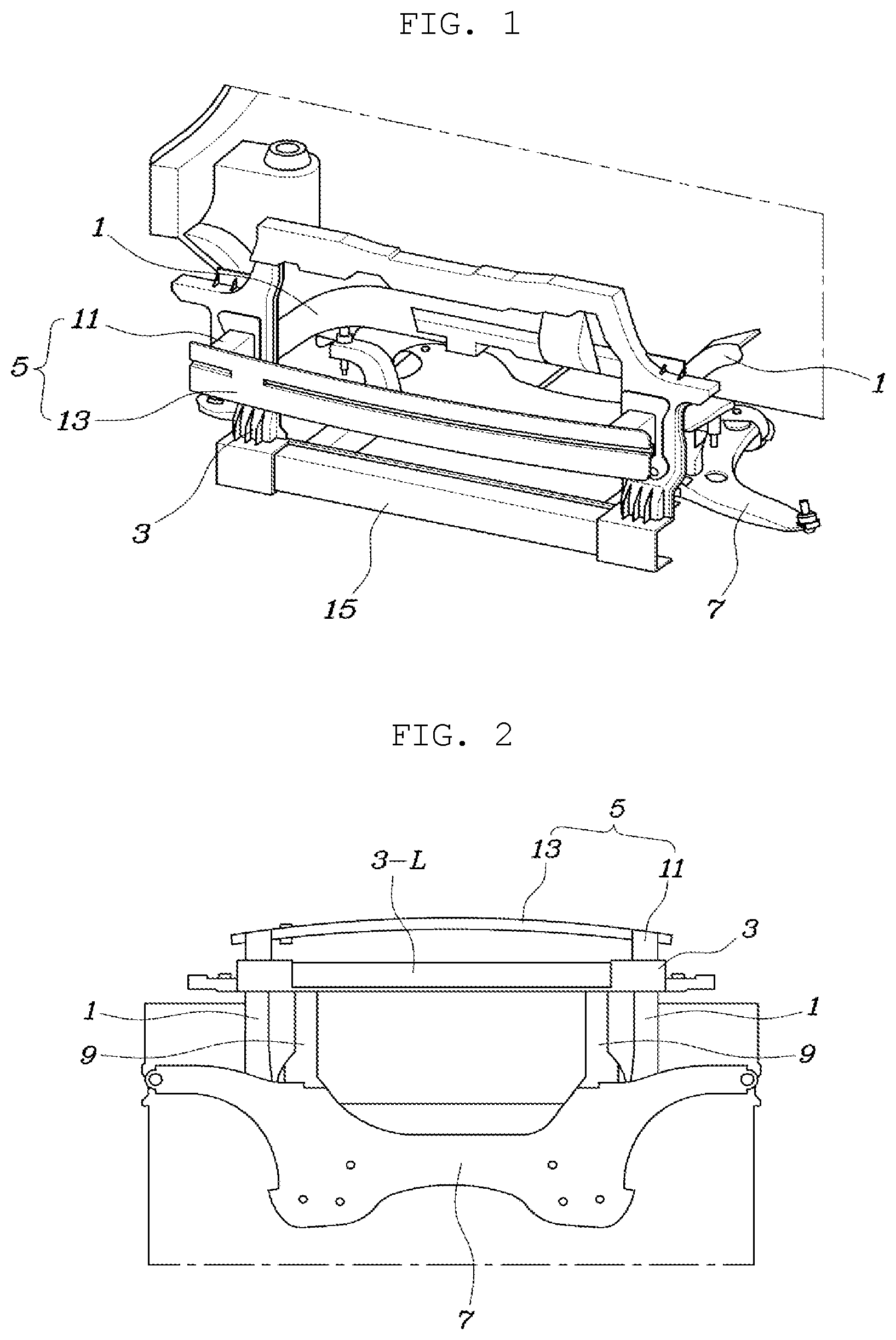
[0023] FIG. 2 is a view illustrating the body structure of FIG. 1 when viewed from the bottom;
[0024] FIG. 3 is a view illustrating the body structure of FIG. 1 when viewed from the side;
[0025] FIG. 4 is a view illustrating some components constituting the body structure of FIG. 1 when viewed from the rear of the body;
[0026] FIG. 5 is a view illustrating some of the components of FIG. 1;
[0027] FIG. 6 is a view illustrating the components of FIG. 5 when viewed from the rear of the body;
[0028] FIG. 7 is a detailed view illustrating that a lower reinforcement member is coupled to the lower portion of a closed loop member;
[0029] FIG. 8 is a longitudinal cross-sectional view illustrating the lower reinforcement member of FIG. 7;
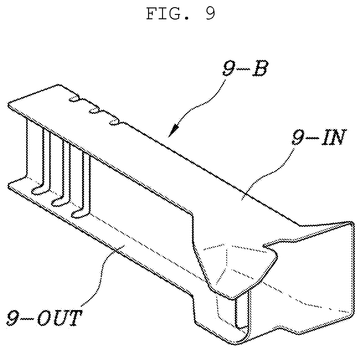
[0030] FIG. 9 is a view illustrating the lower reinforcement member;
[0031] FIG. 10 is a view illustrating the outer panel of FIG. 9;
[0032] FIG. 11 is a view illustrating the lower reinforcement member of FIG. 9 when viewed from a different angle; and
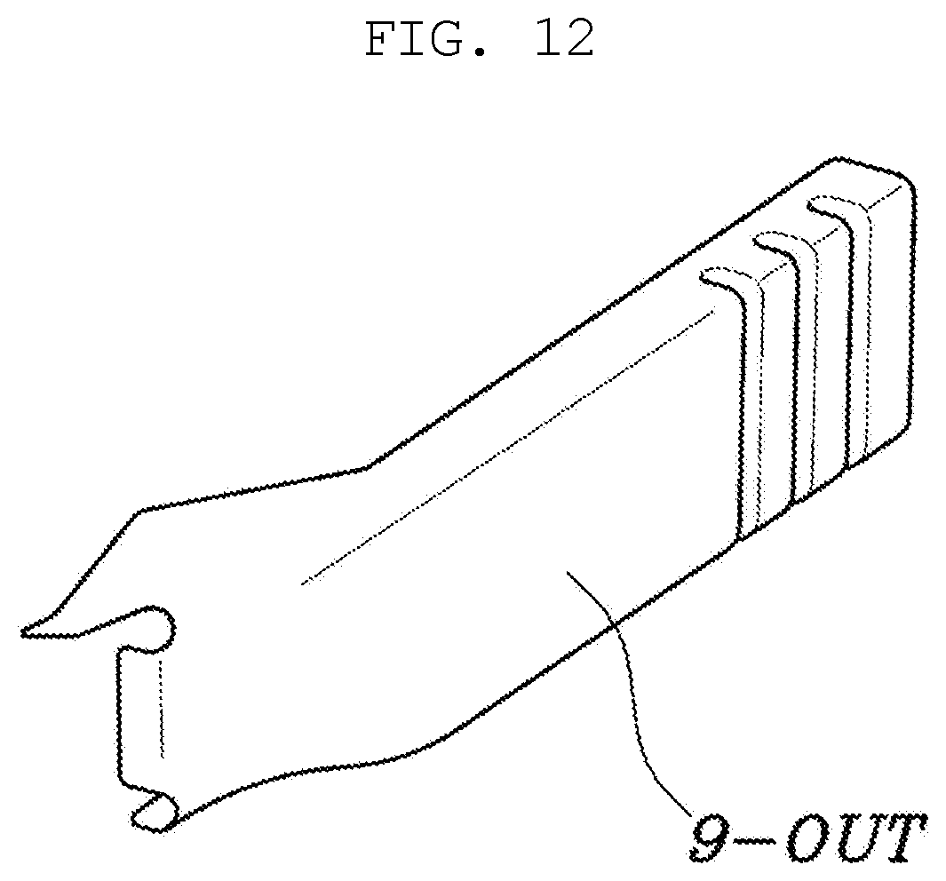
[0033] FIG. 12 is a view illustrating the outer panel of FIG. 11.
[0034] The drawings described herein are for illustration purposes only and are not intended to limit the scope of the present disclosure in any way.
DETAILED DESCRIPTION
[0035] The following description is merely exemplary in nature and is not intended to limit the present disclosure, application, or uses. It should be understood that throughout the drawings, corresponding reference numerals indicate like or corresponding parts and features.
[0036] A front body structure of a vehicle according to exemplary embodiments of the present disclosure will be described below with reference to the accompanying drawings.
[0037] Referring to FIGS. 1 to 12, a front body structure of a vehicle according to an embodiment of the present disclosure includes a closed loop member 3 projected on a front surface of a body to form a closed loop and configured such that both sides of the closed loop are coupled to front ends of front side members 1 at both sides of the body, a back beam assembly 5 coupled to the front part of the closed loop member 3, and lower reinforcement members 9 connecting a lower portion 3-L of the closed loop member 3, at both sides thereof, to the front part of a subframe 7.
[0038] That is, the present disclosure is to distribute and absorb the collision energy due to the forward collision of the vehicle to a plurality of support components, by coupling the closed loop member 3 to the fronts of the front side members 1 provided at both sides of the body, coupling the back beam assembly 5 to the front of the closed loop member 3, and coupling the lower portion 3-L of the closed loop member 3 to the subframe 7 through the lower reinforcement members 9 so that the back beam assembly 5 primarily absorbs the shocks applied from the front of the vehicle and the lower portion 3-L of the closed loop member supported by the lower reinforcement members 9 secondarily supports and absorbs the shocks together therewith.
[0039] In the present embodiment, the closed loop member 3 may be a front end module carrier. A conventional front end module is to constitute a plurality of components, such as a radiator and a lamp, located in the front of the vehicle into a single module, and the front end module carrier is provided to serve as a frame for coupling the front components of the vehicle as described above. Accordingly, the front end module carrier is used as the closed loop member 3 in the present embodiment.
[0040] The front end module carrier is configured by interconnecting an upper portion 3-U, both sides 3-S, and a lower portion 3-L and is located in the front of the vehicle, as illustrated in the drawings. The front end module carrier forms a closed loop when it is projected on the front surface of the vehicle perpendicular to the forward and rearward direction of the vehicle.
[0041] The back beam assembly 5 includes back beam support members 11 coupled to respective front parts of both sides 3-S of the closed loop member 3, and a back beam 13 coupled to the front parts of the two back beam support members 11 while extending in the transverse direction of the body.
[0042] Of course, a bumper may be coupled to the front of the back beam 13, and the back beam support members 11 define a buffer space between the closed loop member 3 and the back beam 13.
[0043] Particularly, in the present embodiment, the back beam support members 11 are installed to be rectilinearly aligned with the front side members 1 in the forward and rearward direction of the body with the closed loop member 3 interposed therebetween.
[0044] Through such arrangement, the back beam 13 and the back beam support members 11 are firmly supported by the front side members 1 without being greatly affected by the shape or strength and position of the closed loop member 3. Thus, the shocks transmitted through the back beam 13 and the back beam support members 11 may be effectively absorbed through the deformation of the back beam 13 and back beam support members 11.
[0045] The lower portion 3-L of the closed loop member 3 may have a cap-type cross-sectional structure that is open toward the rear of the body as illustrated in FIG. 8, to firmly support the shocks acting from the front and to evenly distribute the shocks to the upper and lower sides of the cross section.
[0046] In addition, the lower portion 3-L of the closed loop member 3 may be provided with a steel reinforcement insert 15 extending in the transverse direction of the body, to more effectively support the shocks from the front and to transmit the shocks to the rear through both lower reinforcement members 9.
[0047] That is, the lower portion 3-L of the front end module carrier as the closed loop member 3 may consist of a component formed by injection molding the reinforcement insert 15. When the lower portion 3-L consists of the injection-molded component, it will be provided therein with a plurality of reinforcement ribs 17 as illustrated in FIG. 7.
[0048] As described above, the lower reinforcement members 9 are coupled to the rear of the reinforcement insert 15 of the lower portion 3-L of the closed loop member 3 by a coupling means such as welding or bolting to connect the rear of the reinforcement insert 15 to the subframe 7.
[0049] Each of the lower reinforcement members 9 is configured by coupling an inner panel 9-IN inside the body to an outer panel 9-OUT outside the body with a closed space defined therebetween. The lower reinforcement member 9 may have a polyprism shape that extends in the forward and rearward direction of the body, to support the impact force transmitted from the front and to effectively absorb the impact force by its own deformation.
[0050] In particular, a plurality of shock absorbing beads 9-B may be arranged in the front of the inner panel 9-IN and outer panel 9-OUT of the lower reinforcement member 9 in the longitudinal direction of the lower reinforcement member 9, to absorb the impact force applied from the front as possible in the front of the lower reinforcement member 9 and to relatively improve the safety of the rear space.
[0051] As illustrated in FIGS. 9 and 11, the rear end part of the lower reinforcement members 9 may have a cross-sectional structure that is opened to enlarge an area coupled to the front part of the subframe 7. Thus, the lower reinforcement members 9 may be firmly coupled to the front part of the subframe 7 and the impact force transmitted from the lower reinforcement members 9 may be distributed and transmitted to the widest possible range of the subframe 7.
[0052] Meanwhile, referring to FIG. 3, the closed loop member 3, the front side members 1, the subframe 7, and the lower reinforcement members 9 of the present embodiment may be connected in turn such that the shape thereof projected in the lateral direction of the body forms a closed curve CC therein, to support and distribute the impact force acting from the front by a spatial lattice structure and to provide more improved collision performance of the vehicle.
[0053] Although the exemplary embodiments of the present disclosure have been disclosed for illustrative purposes, those skilled in the art will appreciate that various modifications, additions and substitutions are possible, without departing from the scope and spirit of the disclosure.
* * * * *
D00000
D00001
D00002
D00003
D00004
D00005
D00006
D00007
XML
uspto.report is an independent third-party trademark research tool that is not affiliated, endorsed, or sponsored by the United States Patent and Trademark Office (USPTO) or any other governmental organization. The information provided by uspto.report is based on publicly available data at the time of writing and is intended for informational purposes only.
While we strive to provide accurate and up-to-date information, we do not guarantee the accuracy, completeness, reliability, or suitability of the information displayed on this site. The use of this site is at your own risk. Any reliance you place on such information is therefore strictly at your own risk.
All official trademark data, including owner information, should be verified by visiting the official USPTO website at www.uspto.gov. This site is not intended to replace professional legal advice and should not be used as a substitute for consulting with a legal professional who is knowledgeable about trademark law.