Air Vent And Motor Vehicle
Heth; Marc-Lieven ; et al.
U.S. patent application number 16/930327 was filed with the patent office on 2021-01-28 for air vent and motor vehicle. The applicant listed for this patent is Dr. Ing. h.c. F. Porsche Aktiengesellschaft. Invention is credited to Marc-Lieven Heth, Andreas Schneider.
| Application Number | 20210023913 16/930327 |
| Document ID | / |
| Family ID | 1000004986080 |
| Filed Date | 2021-01-28 |


| United States Patent Application | 20210023913 |
| Kind Code | A1 |
| Heth; Marc-Lieven ; et al. | January 28, 2021 |
AIR VENT AND MOTOR VEHICLE
Abstract
An air vent for a motor vehicle includes a housing with an air channel for feeding air and a hemisphere. The hemisphere is mounted in a rotatable manner within the housing such that air fed through the air channel is deflected on the housing before it exits from the air vent.
| Inventors: | Heth; Marc-Lieven; (Karlsruhe, DE) ; Schneider; Andreas; (Calw, DE) | ||||||||||
| Applicant: |
|
||||||||||
|---|---|---|---|---|---|---|---|---|---|---|---|
| Family ID: | 1000004986080 | ||||||||||
| Appl. No.: | 16/930327 | ||||||||||
| Filed: | July 16, 2020 |
| Current U.S. Class: | 1/1 |
| Current CPC Class: | B60H 1/00871 20130101; B60H 1/00514 20130101; B60H 1/3428 20130101; B60H 2001/3471 20130101 |
| International Class: | B60H 1/34 20060101 B60H001/34; B60H 1/00 20060101 B60H001/00 |
Foreign Application Data
| Date | Code | Application Number |
|---|---|---|
| Jul 22, 2019 | DE | 10 2019 119 732.5 |
Claims
1. An air vent for a motor vehicle, comprising: a housing with an air channel for feeding air; and a hemisphere, wherein the hemisphere is mounted in a rotatable manner within the housing such that air fed through the air channel is deflected on the housing before it exits from the air vent.
2. The air vent as claimed in claim 1, further comprising: a push-rod linkage and a first operating part, wherein the first operating part is mounted in a rotatable manner downstream of the hemisphere, as seen in relation to the air fed through the air channel, and wherein the push-rod linkage couples the hemisphere to the first operating part such that, when the first operating part is rotated in any desired direction of rotation, the hemisphere is carried along in the same direction of rotation.
3. The air vent as claimed in claim 2, wherein the hemisphere and the first operating part have right-angled axes of rotation, as seen in relation to the air channel.
4. The air vent as claimed in claim 1, wherein the housing comprises a spherical housing and a radial bearing that bears the spherical housing, and the hemisphere is mounted within the spherical housing.
5. The air vent as claimed in claim 1, further comprising: a second operating part; a coupling ring; and a metering flap for the air, wherein the coupling ring couples the metering flap to the second operating part.
6. The air vent as claimed in claim 5, further comprising: a rack formed on the coupling ring; a first gearwheel; and a second gearwheel, wherein the metering flap is coupled to the second operating part via the rack, the first gearwheel, and the second gearwheel.
7. The air vent as claimed in claim 5, further comprising coupling rods, wherein the metering flap is coupled to the second operating part via the coupling rods.
8. The air vent as claimed in claim 5, wherein the housing comprises a rotary/slide bearing, and wherein the rotary/slide bearing bears the coupling ring.
9. The air vent as claimed in claim 5, wherein the metering flap is coupled to the second operating part such that rotation of the coupling ring through an acute angle swings round the metering flap between a closed position and an open position.
10. A motor vehicle, comprising: at least one air vent as claimed in claim 1.
Description
CROSS-REFERENCE TO PRIOR APPLICATIONS
[0001] This application claims benefit to German Patent Application No. DE 10 2019 119 732.5, filed on Jul. 22, 2019, the entire disclosure of which is hereby incorporated by reference herein.
FIELD
[0002] The present invention relates to an air vent for a motor vehicle. The present invention also relates to a corresponding motor vehicle.
BACKGROUND
[0003] In automotive engineering, air vents are generally understood to be the air distributors and air nozzles for a wide variety of different air channels in or beneath the dashboard, in the so-called ventilation or air-conditioning roof lining and also behind or beneath the seats of a motor vehicle.
[0004] It is known from DE10 2008 002 958 B3 to provide two hollow-cylinder inserts, which can be moved relative to one another, in order to alter the air-outflow direction.
[0005] An actuation of air vents is known from DE 197 45 932 C2, DE10 2005 035 768 A1 and FR2827815A1.
SUMMARY
[0006] In an embodiment, the present invention provides an air vent for a motor vehicle. The air vent includes a housing with an air channel for feeding air and a hemisphere. The hemisphere is mounted in a rotatable manner within the housing such that air fed through the air channel is deflected on the housing before it exits from the air vent.
BRIEF DESCRIPTION OF THE DRAWINGS
[0007] The present invention will be described in even greater detail below based on the exemplary figures. The invention is not limited to the exemplary embodiments. All features described and/or illustrated herein can be used alone or combined in different combinations in embodiments of the invention. The features and advantages of various embodiments of the present invention will become apparent by reading the following detailed description with reference to the attached drawings which illustrate the following:
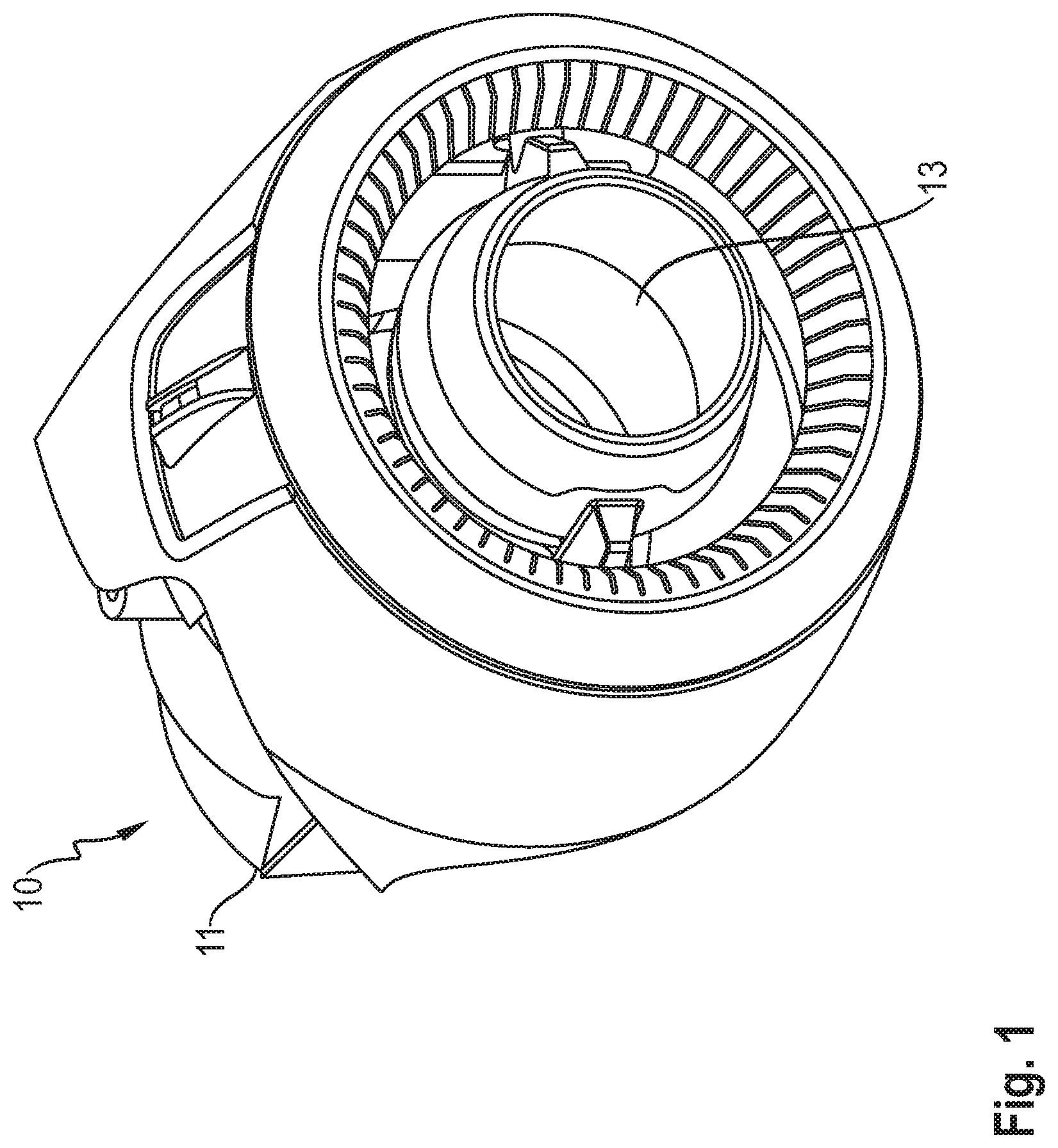
[0008] FIG. 1 shows an isometric view of an air vent in a starting position;
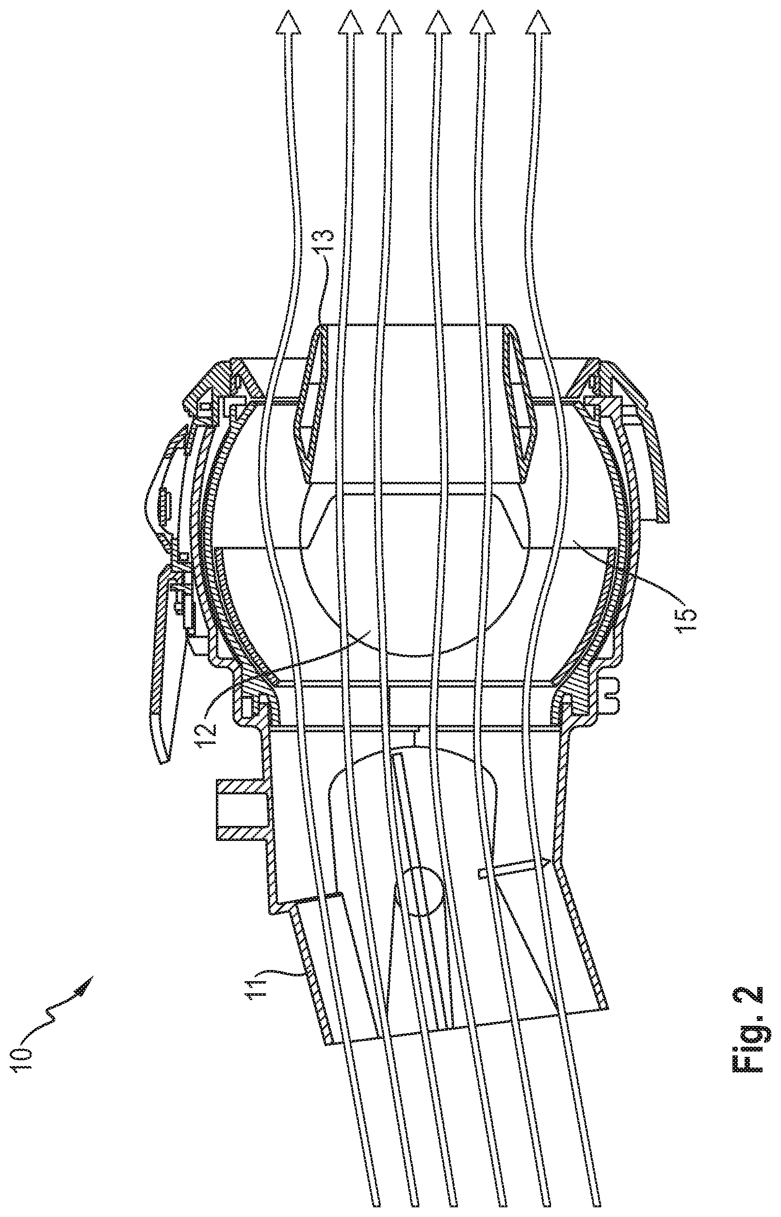
[0009] FIG. 2 shows a longitudinal section through the air vent in the starting position;
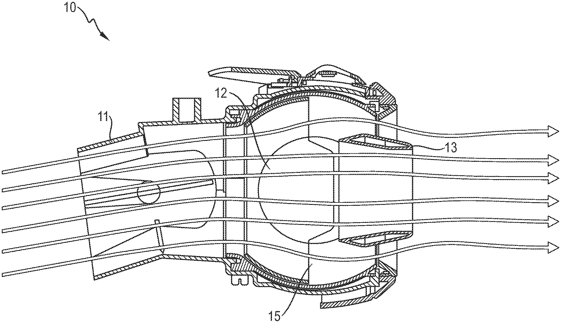
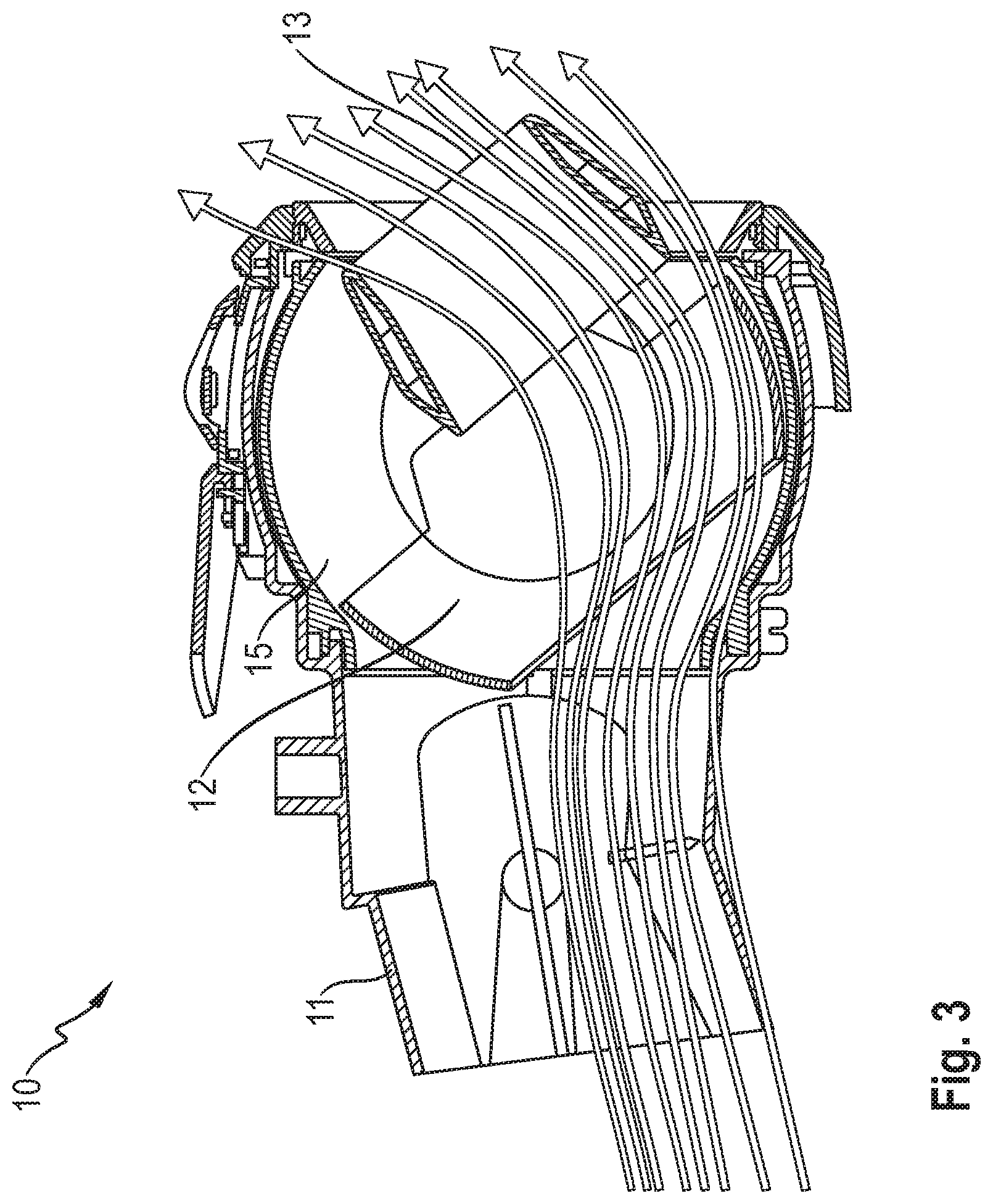
[0010] FIG. 3 shows a section corresponding to FIG. 2, with the air vent directed upward at an angle of 40.degree.;
[0011] FIG. 4 shows a partially transparent side view of the air vent as seen from the left in the position according to FIG. 3;
[0012] FIG. 5 shows a view corresponding to FIG. 4, with the spherical housing represented in full;
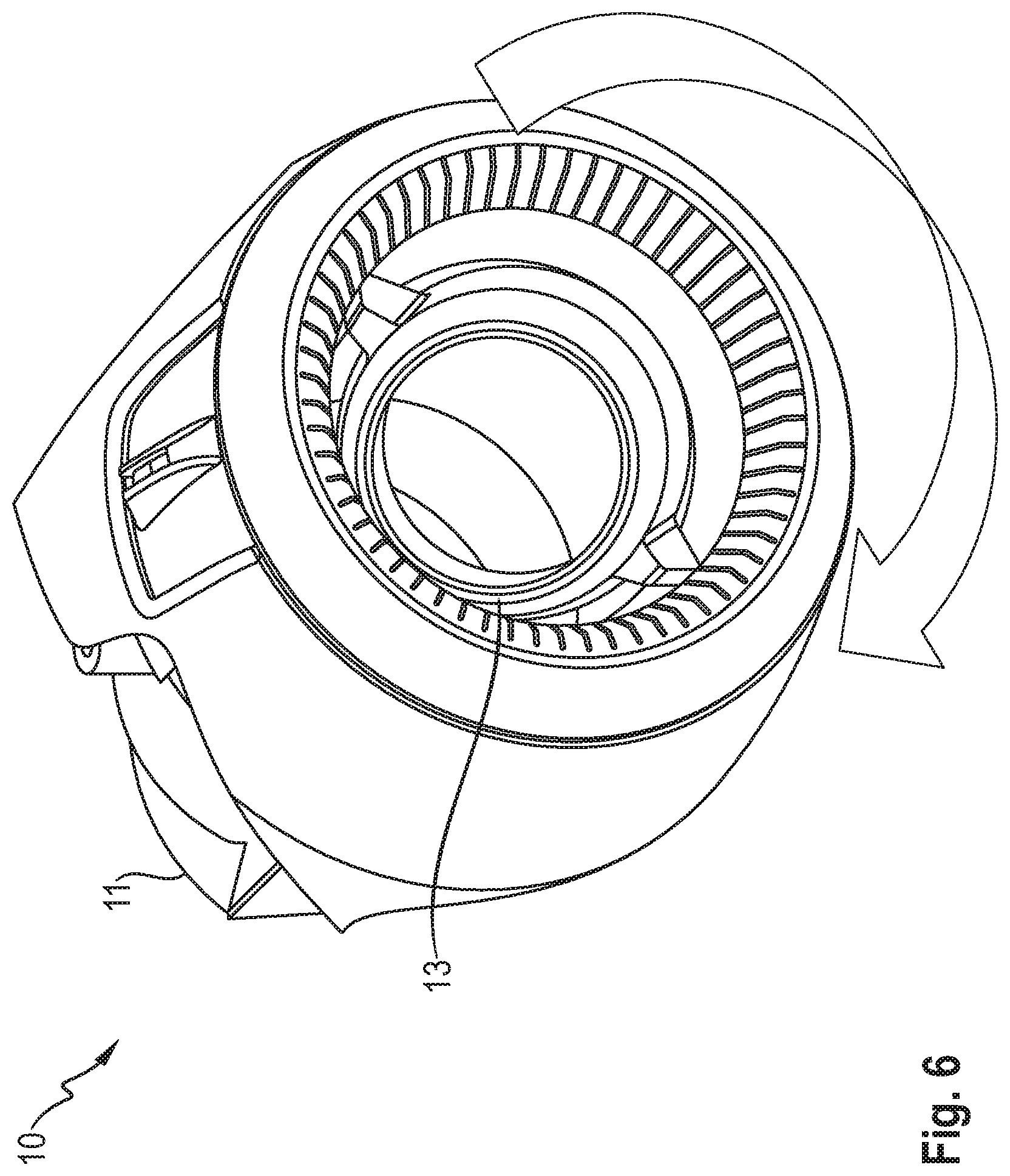
[0013] FIG. 6 shows a view corresponding to FIG. 1, with the air vent rotated to the left;
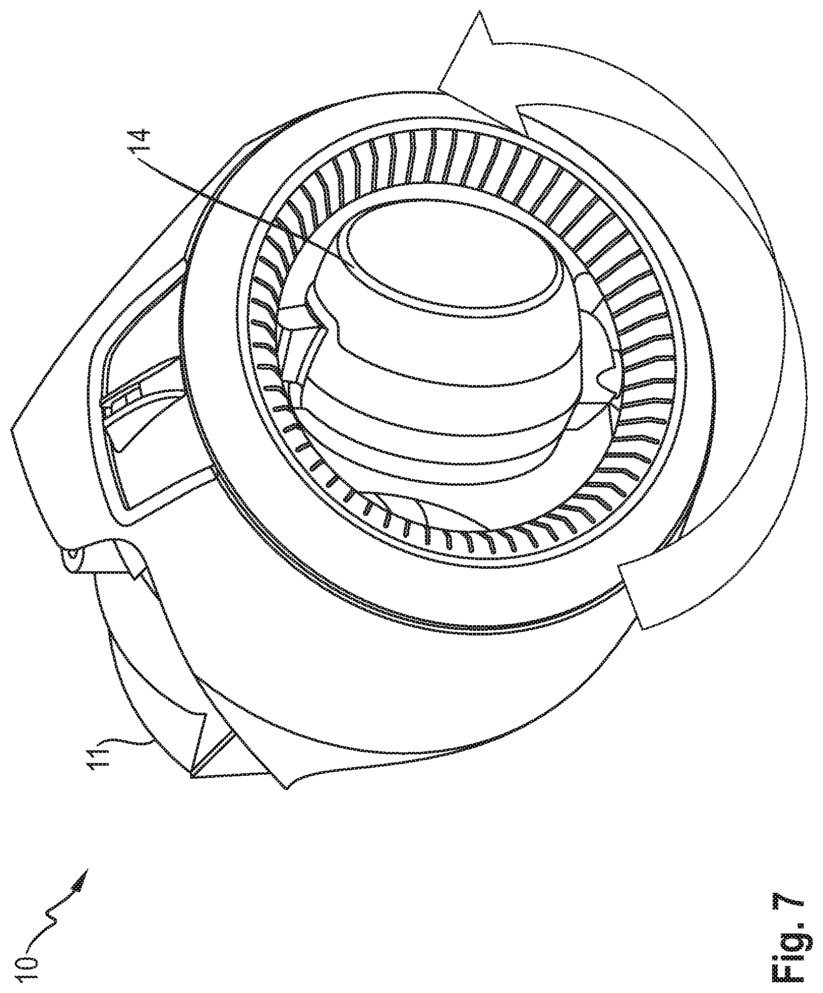
[0014] FIG. 7 shows a view corresponding to FIG. 1, with the air vent rotated to the right;
[0015] FIG. 8 shows a side view as seen from the right of the air vent with a cover plate, coupling ring, gearwheels and metering flap;
[0016] FIG. 9 shows a perspective view of the air vent as seen obliquely from the rear; and
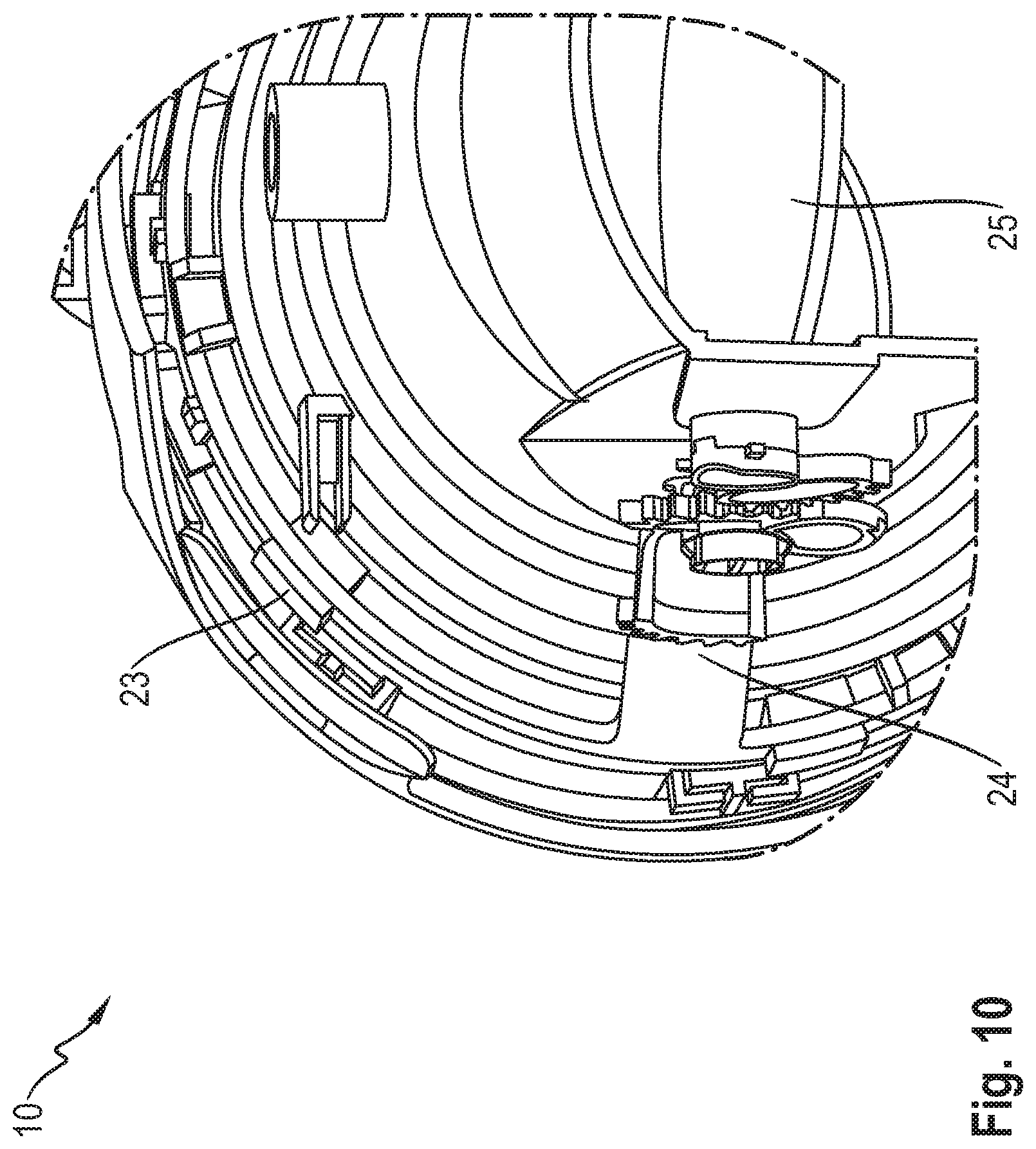
[0017] FIG. 10 shows a detail of FIG. 9.
DETAILED DESCRIPTION
[0018] The disclosure describes an air vent for a motor vehicle and also a motor vehicle having such an air vent.
[0019] Air vents described herein provide for operation that is intuitive, in a manner comparable with conventional louvered air vents and round or spherical air vents, while the shaping of the air vent of the invention differentiates it from conventional air vents.
[0020] FIG. 1 illustrates basic design features of an air vent (10) on the basis of the starting position thereof. The figure shows the housing (11), which accommodates the air channel and on the front side of which is arranged a first operating part (13), which at first glance appears to be conventional.
[0021] As FIG. 2 depicts, a spherical housing (15) is arranged within the housing (11), between the air channel and first operating part (13), and, for its part, bears a hemisphere (12), which serves, in particular, to adjust the angle of distribution.
[0022] The principle of this distribution will now be explained by looking at FIGS. 3, 4 and 5 together. In this illustration, the thumb and forefinger (see FIG. 5) have been used to pivot the operating part through an angle of 40.degree., about its axis of rotation (14--FIG. 4), according to the figure in the upward direction. The hemisphere (12), which is arranged behind the first operating part (13), as seen from the front, is carried along in the same direction of rotation, with a transmission ratio of 1:1, by means of an externally located push-rod linkage (17--FIG. 5). The air stream, which is partially blocked in this way, is thus deflected onto the outer wall of the spherical housing (15) and flows against the cylindrical operating part (13) at the desired angle of distribution.
[0023] If the first operating part (13) is additionally rotated in the clockwise direction (see FIG. 6) or counterclockwise direction (FIG. 7), as seen from the front, this being possible full circle if no stop is provided, the previously set deflecting angle can thus be adjusted in each direction.
[0024] The cinematic air-quantity-metering function will be described, herein below, with reference to FIGS. 8, 9 and 10. For this purpose, the air vent (10) has a metering flap (20--FIG. 8, 25--FIG. 10), which can be finger-operated by way of a second operating part (18). The metering flap (20, 25) is closed by rotation of the second operating part (18) in the clockwise direction, whereas rotation in the counterclockwise direction--as seen from the front in each case--swings round the metering flap (20, 25) into its fully open position (25).
[0025] For this purpose, the second operating part (18) is guided by a cover plate. The latter is connected to a coupling ring (19). The rack (24) on the coupling ring (19) drives a first gearwheel (21). A second gearwheel (22) opens (25--FIG. 10) or closes (20--FIG. 8) the metering flap (20, 25), depending on operation. In an alternative embodiment, transmission is possible, without departing from the framework of the invention, by means of coupling rods rather than gearwheels (21, 22).
[0026] While the invention has been illustrated and described in detail in the drawings and foregoing description, such illustration and description are to be considered illustrative or exemplary and not restrictive. It will be understood that changes and modifications may be made by those of ordinary skill within the scope of the following claims. In particular, the present invention covers further embodiments with any combination of features from different embodiments described above and below. Additionally, statements made herein characterizing the invention refer to an embodiment of the invention and not necessarily all embodiments.
[0027] The terms used in the claims should be construed to have the broadest reasonable interpretation consistent with the foregoing description. For example, the use of the article "a" or "the" in introducing an element should not be interpreted as being exclusive of a plurality of elements. Likewise, the recitation of "or" should be interpreted as being inclusive, such that the recitation of "A or B" is not exclusive of "A and B," unless it is clear from the context or the foregoing description that only one of A and B is intended. Further, the recitation of "at least one of A, B and C" should be interpreted as one or more of a group of elements consisting of A, B and C, and should not be interpreted as requiring at least one of each of the listed elements A, B and C, regardless of whether A, B and C are related as categories or otherwise. Moreover, the recitation of "A, B and/or C" or "at least one of A, B or C" should be interpreted as including any singular entity from the listed elements, e.g., A, any subset from the listed elements, e.g., A and B, or the entire list of elements A, B and C.
* * * * *
D00000
D00001
D00002
D00003
D00004
D00005
D00006
D00007
D00008
D00009
D00010
XML
uspto.report is an independent third-party trademark research tool that is not affiliated, endorsed, or sponsored by the United States Patent and Trademark Office (USPTO) or any other governmental organization. The information provided by uspto.report is based on publicly available data at the time of writing and is intended for informational purposes only.
While we strive to provide accurate and up-to-date information, we do not guarantee the accuracy, completeness, reliability, or suitability of the information displayed on this site. The use of this site is at your own risk. Any reliance you place on such information is therefore strictly at your own risk.
All official trademark data, including owner information, should be verified by visiting the official USPTO website at www.uspto.gov. This site is not intended to replace professional legal advice and should not be used as a substitute for consulting with a legal professional who is knowledgeable about trademark law.