Chambers To Receive Fluids By Negative Pressures
LAHMANN; John ; et al.
U.S. patent application number 17/045739 was filed with the patent office on 2021-01-28 for chambers to receive fluids by negative pressures. The applicant listed for this patent is HEWLETT-PACKARD DEVELOPMENT COMPANY, L.P.. Invention is credited to Silam J CHOY, Pavel KORNILOVICH, John LAHMANN.
| Application Number | 20210023555 17/045739 |
| Document ID | / |
| Family ID | 1000005166076 |
| Filed Date | 2021-01-28 |
| United States Patent Application | 20210023555 |
| Kind Code | A1 |
| LAHMANN; John ; et al. | January 28, 2021 |
CHAMBERS TO RECEIVE FLUIDS BY NEGATIVE PRESSURES
Abstract
An example device includes a chamber including a fluid inlet, a fluid outlet, and a negative-pressure port. The negative-pressure port is positioned relative to the fluid inlet to draw a droplet of a fluid from the fluid inlet into the chamber when the fluid is applied to the fluid inlet and negative pressure is applied to the negative-pressure port. The fluid outlet is positioned relative to the fluid inlet to collect the droplet. The example device further includes a downstream microfluidic channel connected to the fluid outlet of the chamber. The downstream microfluidic channel communicates capillary action to the fluid outlet of the chamber. The capillary action resists flow of the fluid from the fluid outlet into the chamber induced by the negative pressure applied to the negative-pressure port.
| Inventors: | LAHMANN; John; (Corvallis, OR) ; CHOY; Silam J; (Corvallis, OR) ; KORNILOVICH; Pavel; (Corvallis, OR) | ||||||||||
| Applicant: |
|
||||||||||
|---|---|---|---|---|---|---|---|---|---|---|---|
| Family ID: | 1000005166076 | ||||||||||
| Appl. No.: | 17/045739 | ||||||||||
| Filed: | November 21, 2018 | ||||||||||
| PCT Filed: | November 21, 2018 | ||||||||||
| PCT NO: | PCT/US2018/062347 | ||||||||||
| 371 Date: | October 6, 2020 |
Related U.S. Patent Documents
| Application Number | Filing Date | Patent Number | ||
|---|---|---|---|---|
| PCT/US2018/029169 | Apr 24, 2018 | |||
| 17045739 | ||||
| Current U.S. Class: | 1/1 |
| Current CPC Class: | B01L 2400/0406 20130101; B01L 2300/0883 20130101; B01L 3/502715 20130101; B01L 2400/0442 20130101; B01L 3/50273 20130101 |
| International Class: | B01L 3/00 20060101 B01L003/00 |
Claims
1. A device comprising: a chamber including a fluid inlet, a fluid outlet, and a negative-pressure port, the negative-pressure port positioned relative to the fluid inlet to draw a droplet of a fluid from the fluid inlet into the chamber when the fluid is applied to the fluid inlet and negative pressure is applied to the negative-pressure port, the fluid outlet positioned relative to the fluid inlet to collect the droplet; and a downstream microfluidic channel connected to the fluid outlet of the chamber, the downstream microfluidic channel to communicate capillary action to the fluid outlet of the chamber, the capillary action to resist flow of the fluid from the fluid outlet into the chamber induced by the negative pressure applied to the negative-pressure port.
2. The device of claim 1, further comprising a droplet ejector at an end of the downstream microfluidic channel to eject droplets to draw fluid through the downstream microfluidic channel, the droplet ejector further to provide the capillary action.
3. The device of claim 2, further comprising a target microfluidic network communicating with the downstream microfluidic channel between the chamber and the droplet ejector, the target microfluidic network to perform a process with the fluid.
4. The device of claim 3, wherein the process comprises a nucleic acid amplification process.
5. The device of claim 1, further comprising a droplet ejector connected to the negative-pressure port to provide the negative pressure.
6. The device of claim 1, further comprising a magnet at the chamber.
7. The device of claim 1, further comprising a dried reagent in the chamber.
8. The device of claim 1, wherein the chamber is of a mesofluidic scale.
9. The device of claim 1, wherein a capillary break separates the negative-pressure port from the fluid inlet or the fluid outlet.
10. A method comprising: applying a negative pressure to a negative-pressure port of a chamber to draw a droplet of a fluid from a fluid inlet of the chamber into the chamber; collecting the droplet at a fluid outlet of the chamber, the fluid outlet positioned below the fluid inlet relative to a force of gravity; and communicating capillary action from a downstream microfluidic channel to the fluid outlet of the chamber, the capillary action to resist flow of the fluid from the fluid outlet into the chamber induced by the negative pressure applied to the negative-pressure port.
11. The method of claim 10, further comprising ejecting droplets using a droplet ejector at an end of the downstream microfluidic channel to draw fluid through the downstream microfluidic channel.
12. The method of claim 11, further comprising performing a process with the fluid at a target microfluidic network communicating with the downstream microfluidic channel between the chamber and the droplet ejector.
13. The method of claim 12, comprising performing a nucleic acid amplification process with the fluid at the target microfluidic network.
14. The method of claim 10, further comprising ejecting droplets using a droplet ejector connected to the negative-pressure port to apply the negative pressure to the negative-pressure port.
15. A device comprising: a housing; a chamber defined by the housing, the chamber including a fluid inlet, a fluid outlet, and a negative-pressure port; a downstream microfluidic channel connected to the fluid outlet of the chamber, the downstream microfluidic channel to resist backflow of fluid from the fluid outlet into the chamber induced by negative pressure applied to the negative-pressure port; a feature at the housing, the feature shaped to position the fluid outlet below the fluid inlet relative to a force of gravity when the feature is mated with a complementary feature at an analysis device; and a signal interface to receive a signal from the analysis device to apply the negative pressure to the negative-pressure port to draw a droplet of fluid from the fluid inlet into the chamber.
Description
BACKGROUND
[0001] Microfluidic systems may be used to perform a variety of chemical, biological, and biochemical processes, such as nucleic acid testing. Delivery of reagents to a process site may be accomplished in a variety of ways.
BRIEF DESCRIPTION OF THE DRAWINGS
[0002] FIG. 1 is a side cross-sectional view of an example device including a chamber that may receive fluid by application of a negative pressure to a negative pressure port.
[0003] FIG. 2 is a side cross-sectional view of an example device including a chamber that may receive fluid by application of a negative pressure using a droplet ejector.
[0004] FIG. 3 is a flowchart of an example method to provide fluid to a chamber by application of a negative pressure to a negative pressure port.
[0005] FIG. 4 is a side cross-sectional view of an example device including a chamber containing a magnet to interact with fluid drawn into the chamber by application of a negative pressure using a droplet ejector.
[0006] FIG. 5 is a side cross-sectional view of an example device including a chamber that may receive fluid by application of a negative pressure using a droplet ejector unit primed with drive fluid.
[0007] FIG. 6 is a side cross-sectional view of an example device including a chamber that may receive fluid by application of a negative pressure using a droplet ejector and that may provide fluid to several target microfluidic networks.
[0008] FIG. 7 is a side cross-sectional view of example vertically arranged devices, each including a chamber that may receive fluid by application of a negative pressure to a negative pressure port.
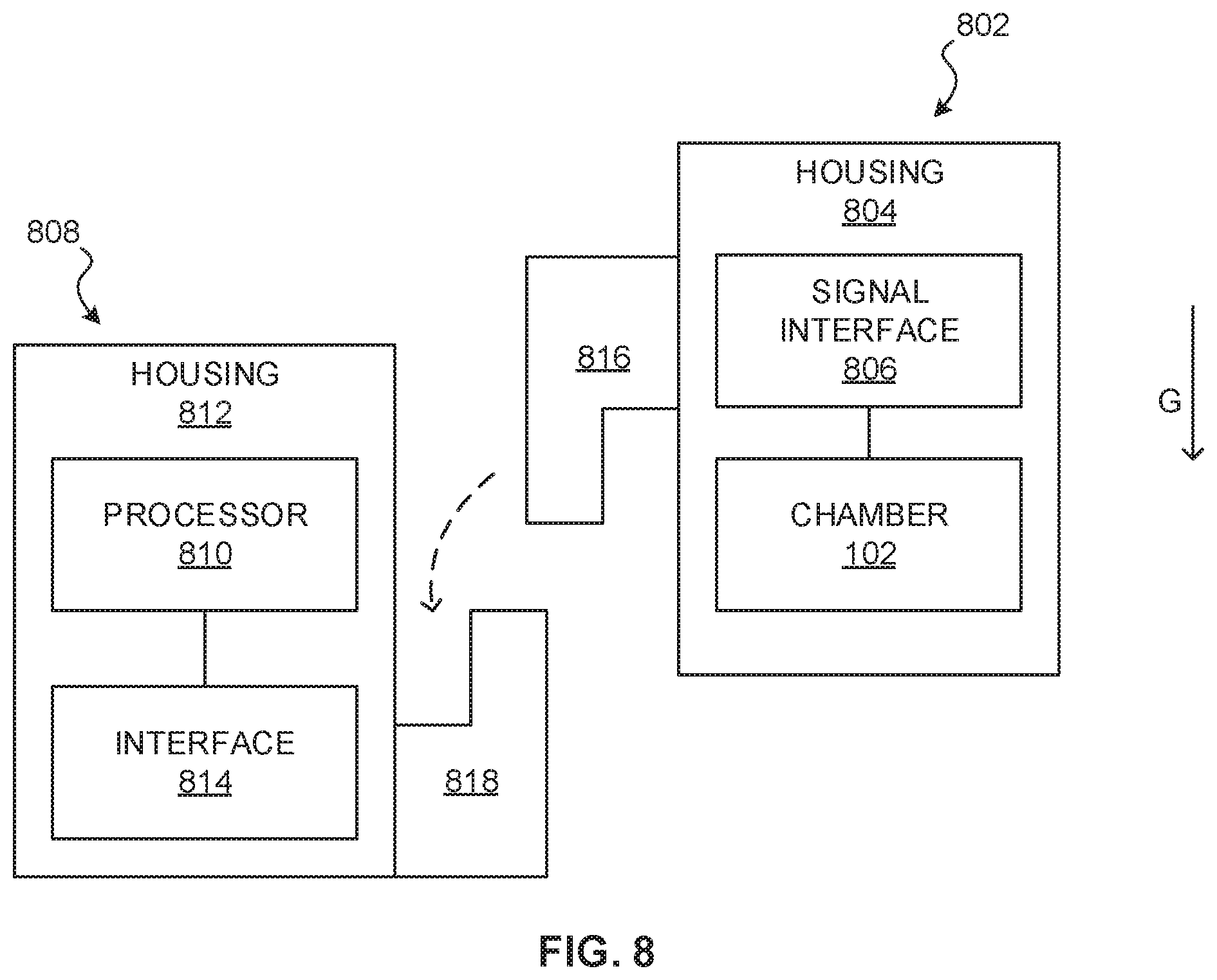
[0009] FIG. 8 is a schematic diagram of an example cartridge including a chamber that may receive fluid by application of a negative pressure to a negative pressure port.
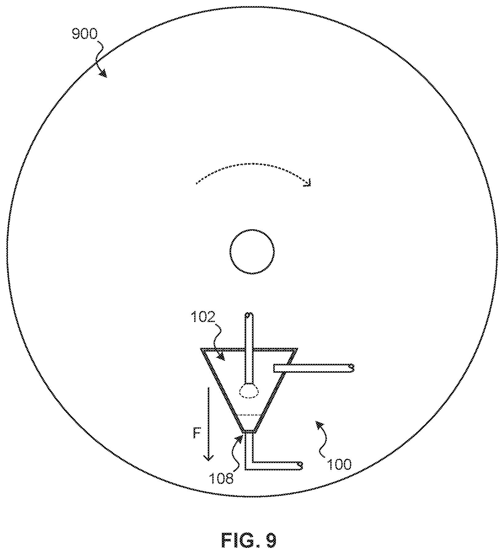
[0010] FIG. 9 is a schematic diagram of an example device including a chamber that may receive fluid by application of a negative pressure to a negative pressure port, the example device being provided to a centrifuge.
DETAILED DESCRIPTION
[0011] A filter flask or Buchner Flask is typically not used in a microfluidic system, as such a flask is large scale and required human intervention to remove collected material, even when a bottom drain is provided. Further, known filter flasks are generally not suited for microfluidic applications, such as nucleic acid testing using a target microfluidic network.
[0012] This disclosure provides a mesofluidic chamber into which upstream fluid may be drawn when downstream microfluidic output of the chamber is stopped. This may facilitate performing mixing, reaction, concentration, or other manipulation within the chamber.
[0013] The chamber has a fluid inlet and a fluid outlet. The fluid inlet may be positioned above the fluid outlet and separated from the fluid outlet by a distance to form a capillary break. A negative pressure port is provided to the chamber to apply low pressure to the air or other gas within the chamber. The low pressure draws fluid into the chamber via the fluid inlet. The fluid inlet may be shaped to form droplets of incoming fluid. Droplets may collect near the fluid outlet at the bottom of the chamber.
[0014] The fluid outlet of the chamber is connected to a downstream microfluidic channel that provides resistance to flow via capillary action. The downstream microfluidic channel may feed a target microfluidic network for a given application, such as thermocycling for a polymerase chain reaction (PCR) process. A thermal inkjet (TIJ) or piezo ejector array may be provided to draw fluid through the downstream microfluidic channel. The resistance provided by the downstream microfluidic channel and any downstream microfluidic components provided holds fluid at the outlet against the low pressure used to draw droplets into the chamber.
[0015] Holding fluid at the outlet allows for mixing, reaction, concentration, or other manipulation to be performed within the chamber. When the process is complete, the low pressure may be removed and fluid may be flowed through the outlet and into the downstream microfluidic channel and any downstream fluid components that it feeds.
[0016] The mesofluidic chamber allows for fluid manipulations at microfluidic scale, and such manipulations may be controlled by droplet ejectors as opposed to human intervention.
[0017] In the examples, a device includes a chamber and a downstream microfluidic channel. The chamber includes a fluid inlet, a fluid outlet, and a negative-pressure port. The negative-pressure port is positioned relative to the fluid inlet to draw a droplet of a fluid from the fluid inlet into the chamber when the fluid is applied to the fluid inlet and negative pressure is applied to the negative-pressure port. The fluid outlet is positioned relative to the fluid inlet to collect the droplet.
[0018] The downstream microfluidic channel is connected to the fluid outlet of the chamber. The downstream microfluidic channel is to communicate capillary action to the fluid outlet of the chamber. The capillary action is to resist flow of the fluid from the fluid outlet into the chamber induced by the negative pressure applied to the negative-pressure port.
[0019] The device can further include a droplet ejector at an end of the downstream microfluidic channel to eject droplets to draw fluid through the downstream microfluidic channel. The droplet ejector can further to provide the capillary action.
[0020] The device can further include a target microfluidic network communicating with the downstream microfluidic channel between the chamber and the droplet ejector. The target microfluidic network is to perform a process with the fluid.
[0021] The process can include a nucleic acid amplification process.
[0022] The device can further include a droplet ejector connected to the negative-pressure port to provide the negative pressure.
[0023] The device can further include a magnet at the chamber.
[0024] The device can further include a dried reagent in the chamber.
[0025] The chamber can be of a mesofluidic scale.
[0026] A capillary break can separate the negative-pressure port from the fluid inlet or the fluid outlet.
[0027] In some examples, a device includes a housing; a chamber defined by the housing; a downstream microfluidic channel; a feature at the housing; and a signal interface. The chamber includes a fluid inlet, a fluid outlet, and a negative-pressure port. The downstream microfluidic channel is connected to the fluid outlet of the chamber. The downstream microfluidic channel is to resist backflow of fluid from the fluid outlet into the chamber induced by negative pressure applied to the negative-pressure port. The feature is shaped to position the fluid outlet below the fluid inlet relative to a force of gravity when the feature is mated with a complementary feature at an analysis device. The signal interface is to receive a signal from the analysis device to apply the negative pressure to the negative-pressure port to draw a droplet of fluid from the fluid inlet into the chamber.
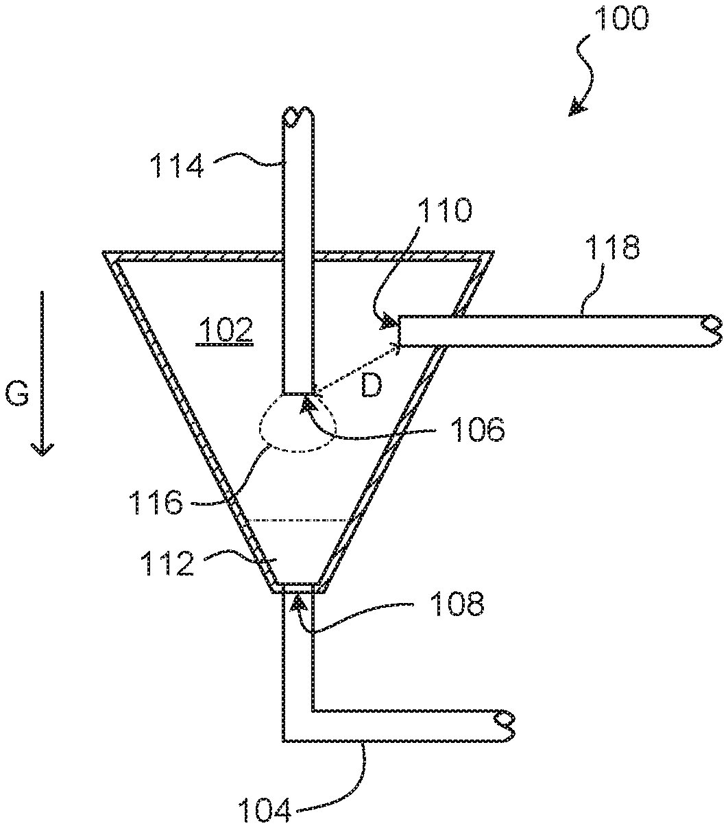
[0028] With reference to FIG. 1, an example device 100 includes a chamber 102 and a downstream microfluidic channel 104.
[0029] The chamber 102 includes a fluid inlet 106, a fluid outlet 108, and a negative-pressure port 110. The chamber 102 may be funnel shaped and may be oriented such that the chamber 102 narrows in the direction of gravity G or other force. That is, the chamber 102 may be shaped and oriented with respect to gravity to collect fluid 112 at the fluid outlet 108.
[0030] The fluid inlet 106 may be located at the end of an inlet channel 114 that extends into the chamber 102. Such a channel may have a tube or conduit structure that extends into the chamber 102. A fluid or a constituent thereof may be provided to the chamber 102 via the fluid inlet 106. A constituent provided via the fluid inlet 106 may include a fluid that reacts, mixes, or otherwise cooperates with a material present the chamber 102, such as a dry reagent (e.g., solid, powder, etc.), magnet, or similar, to generate a fluid that is to be drawn through the fluid outlet 108.
[0031] The fluid outlet 108 may be an opening that is positioned relative to the fluid inlet 106 to collect incoming droplets of fluid. The fluid outlet 108 may be located at or near the bottom of the chamber 102. Fluid may be outputted from the chamber 102 via the fluid outlet 108. The fluid outlet 108 communicates with the downstream microfluidic channel 104 to feed fluid from the chamber 102 into the downstream microfluidic channel 104.
[0032] The negative-pressure port 110 is positioned above the fluid outlet 108, with respective to gravity G, and relative to the fluid inlet 106 to draw a droplet 116 of a fluid from the fluid inlet 106 into the chamber 102. The negative-pressure port 110 may be positioned a minimum distance D from the fluid inlet 106 to prevent a fluid droplet 116 from being drawn into the negative-pressure port 110 by wicking, air/gas movement, or similar. The minimum distance D may define a capillary break. The negative-pressure port 110 and chamber 102 are mutually arranged to prevent the droplet 116 from coming into contact with a surface that may wick the droplet 116 to the negative-pressure port 110. For example, a channel 118 that communicates with the negative-pressure port 110 may have a tube or conduit structure that extends into the chamber 102 to provide a capillary break.
[0033] A capillary break may be provided to separate the negative-pressure port 110 from the fluid input 106 and fluid output 108 to prevent wicking of fluid to the negative-pressure port 110 by selected geometry (such as depicted), a surface energy attribute of the fluid inlet 106 or fluid outlet 108, or a combination of such.
[0034] The chamber 102 may be mesofluidic in scale relative to the fluid outlet 108 and the downstream microfluidic channel 104. Mesofluidic scale may be a scale that includes features having characteristic sizes of between approximately 0.1 mm and approximately 10 mm. The chamber 102 is not vented to atmosphere. Openings in the chamber 102 may be limited to a fluid inlet 106, a fluid outlet 108, and a negative-pressure port 110.
[0035] The downstream microfluidic channel 104 is connected to the fluid outlet 108 and communicates capillary action to the fluid outlet 108. Such capillary action is substantial enough to resist flow of fluid from the fluid outlet 108 into the chamber 102 as may be induced by negative pressure applied to the negative-pressure port 110. Such capillary action may be provided by the microfluidic channel 104, particularly if it is relatively narrow with respect to the properties of the fluid. Sufficient capillary action may additionally or alternatively be provided by a downstream microfluidic component, such as a microfluidic network or droplet ejector.
[0036] In operation, fluid may be applied to the fluid inlet 106 from an upstream source, such as a vented fluid reservoir. Negative pressure may be applied to the negative-pressure port 110. When negative pressure is applied to the negative-pressure port 110, the resulting reduced pressure in the chamber 102 draws fluid through the inlet channel 114 and causes a droplet 116 of fluid to form at the fluid inlet 106. The droplet 116 remains at the fluid inlet 106 until detachment, as may be determined by surface tension, contact angle, liquid mass, gravity, or similar factor. The droplet 116 breaks free and falls towards the lower portion of the chamber 102. Droplets 116 may collect as bulk fluid 112 at the bottom of the chamber 102. At the same time, capillary action provided by the downstream microfluidic channel 104 and any other downstream microfluidic component communicating with the channel 104 reduces the effect of the negative pressure on the bulk fluid 112 at the bottom of the chamber 102 to reduce the risk that fluid 112 is drawn into the negative-pressure port 110.
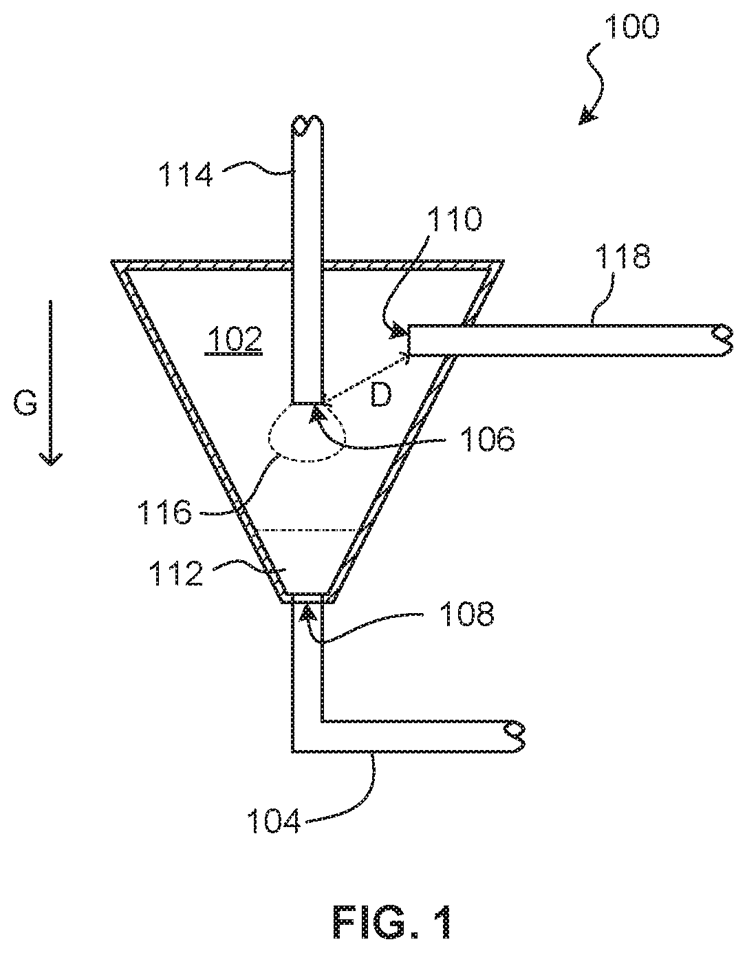
[0037] FIG. 2 shows an example device 200. Features and aspects of the other devices and systems described herein may be used with the device 200 and vice versa. Like reference numerals denote like elements and description of like elements is not repeated here.
[0038] The device 200 includes a chamber 102, a downstream microfluidic channel 104, and a fluid inlet 106, a fluid outlet 108, and a negative-pressure port 110 provided to the chamber 102, as described elsewhere herein.
[0039] The device 200 further includes a first droplet ejector 202 at an end of the downstream microfluidic channel 104. An array of droplet ejectors 202 may be provided. The first droplet ejector 202 is to eject fluid droplets to draw fluid through the downstream microfluidic channel 104. Further, the first droplet ejector 202 provides capillary action to reduce the tendency for fluid 112 in the chamber 102 to be drawn towards to the negative-pressure port 110.
[0040] The device 200 further includes a target microfluidic network 204 that communicates with the downstream microfluidic channel 104. The target microfluidic network 204 is situated between the chamber 102 and the first droplet ejector 202. The target microfluidic network 204 performs a process with fluid drawn through the microfluidic channel 104 by action of the first droplet ejector 202.
[0041] The target microfluidic network 204 may include a passive component, such as a network of microfluidic channels, which may be made of silicon, silicon oxide, photoresist, polydimethylsiloxane (PDMS), cyclic olefin copolymer (COC), other plastics, glass, or other materials that may be made using micro-fabrication technologies. The target microfluidic network 204 may contain a solid compound to interact with fluid delivered by the channel 104. A solid compound may be solid in bulk, may be a powder or particulate, may be integrated into a fibrous material, or similar.
[0042] The target microfluidic network 204 may include an active component. Examples of active components include a pump, sensor, mixing chamber, channel, heater, reaction chamber, droplet ejector, or similar component to perform further action on fluid delivered by the channel 104.
[0043] In various examples, the target microfluidic network 204 includes microfluidic structure to implement an analytical process, such as a nucleic acid testing process that uses nucleic acid amplification (NAT), such as polymerase chain reaction (PCR), real-time or quantitative polymerase chain reaction (qPCR), reverse transcription polymerase chain reaction (RT-PCR), loop mediated isothermal amplification (LAMP), and similar.
[0044] The device 200 further includes a second droplet ejector 206 connected to the negative-pressure port 110 to provide negative pressure or partial vacuum to the chamber 102. An array of droplet ejectors 206 may be provided. The second droplet ejector 206 may be connected to the negative-pressure port 110 by a negative-pressure channel 118. The second droplet ejector 206 is to eject fluid droplets to draw fluid through the negative-pressure channel 118 and away from the chamber 102 to induce a negative pressure in the chamber 102.
[0045] The first and second droplet ejectors 202, 206 may be formed at a substrate and such a substrate may have multiple layers. The substrate may include silicon, glass, photoresist (e.g., SU-8), or similar materials. A droplet ejector 202, 206 may include a jet element, such as a resistive heater, a piezoelectric element, or similar device that may implement inkjet droplet jetting techniques, such as thermal inkjet (TIJ) jetting. The jet element is controllable to draw fluid from the respective channel 104, 118 to jet fluid droplets out an orifice. An array having any number of droplet ejectors 202, 206 may be provided.
[0046] The downstream and negative pressure channels 104, 118 may be primed with fluid. For example, the downstream microfluidic channel 104 may be preloaded with a drive fluid or a working fluid. A drive fluid serves to communicate negative pressure and be ejected without being used by the analytical process implemented by the target microfluidic network 204. Working fluid may be used by the target microfluidic network 204. The negative pressure channel 118 may be preloaded with a drive fluid. Movement of the drive fluid away from the negative-pressure port 110 induces negative pressure in the chamber 102. In other examples, a channel 104, 118 is partially filled with drive fluid. Specifically, the downstream microfluidic channel 104 may be empty of drive fluid in a segment upstream of the target microfluidic network 204, so as to reduce the likelihood of contamination of the target microfluidic network 204 with drive fluid. Likewise, a small segment of the channel 104 downstream of the target microfluidic network 204 may be empty of drive fluid, so as to reduce the likelihood of contamination of the target microfluidic network 204 in case of a small amount of backflow.
[0047] In some examples, the devices and systems described herein can be used with a method for providing fluid to a chamber by application of a negative pressure. An example method includes applying a negative pressure to a negative-pressure port of a chamber to draw a droplet of a fluid from a fluid inlet of the chamber into the chamber; collecting the droplet at a fluid outlet of the chamber, in which the fluid outlet positioned below the fluid inlet relative to a force of gravity; and communicating capillary action from a downstream microfluidic channel to the fluid outlet of the chamber. The capillary action is to resist flow of the fluid from the fluid outlet into the chamber induced by the negative pressure applied to the negative-pressure port.
[0048] The method can further include ejecting droplets using a droplet ejector at an end of the downstream microfluidic channel to draw fluid through the downstream microfluidic channel.
[0049] The method can further include performing a process with the fluid at a target microfluidic network communicating with the downstream microfluidic channel between the chamber and the droplet ejector.
[0050] A nucleic acid amplification process can be performed with the fluid at the target microfluidic network.
[0051] The method can further include ejecting droplets using a droplet ejector connected to the negative-pressure port to apply the negative pressure to the negative-pressure port.
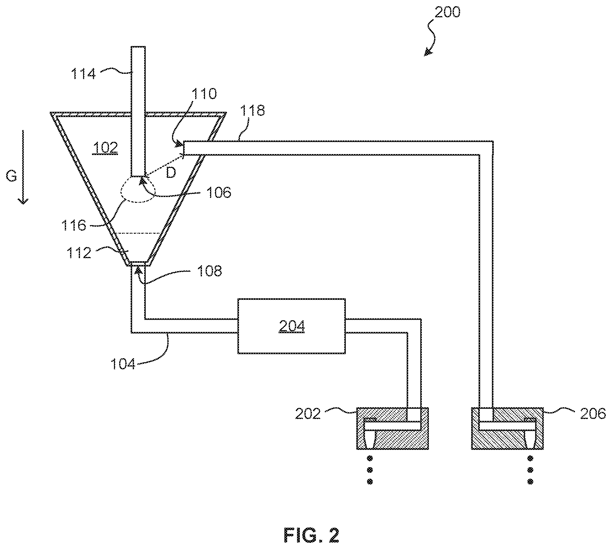
[0052] FIG. 3 shows an example method 300. The method 300 may be performed by any of the systems and devices described herein, such as the device 200 which will be used as an example. The method starts at block 302.
[0053] At block 304, negative pressure is applied to a negative-pressure port 110 of a chamber 102 to draw a droplet 116 of a fluid from a fluid inlet 106 of the chamber 102 into the chamber 102. Negative pressure may be applied at the negative pressure port 110 by ejecting droplets using a droplet ejector 206 in fluid communication with the negative-pressure port 110.
[0054] At block 306, the droplet 116 is collected at a fluid outlet 108 of the chamber 102. The fluid outlet 108 is positioned below the fluid inlet 106 and the droplet 116 falls from the fluid inlet 106 towards the fluid outlet 108. The droplet 116 may accumulate as fluid 112 at the bottom of the chamber 102. A reaction or other fluid manipulation may take place at the bottom of the chamber 102.
[0055] During this process, as shown at block 308, a force due to capillary action is communicated from a downstream microfluidic channel 104 to the fluid outlet 108 of the chamber 102. Capillary action resists flow of the fluid 112 from the vicinity of the fluid outlet 108 further back into the chamber 102, as may be induced by the negative pressure applied to the negative-pressure port 110. Capillary action may be provided by the downstream microfluidic channel 104, a target microfluidic network 204 that communicates with the downstream microfluidic channel 104, a droplet ejector 202 that terminates the downstream microfluidic channel 104, or a combination of such. Backflow of fluid 112, such as flow into the negative-pressure port 110, may thus be prevented.
[0056] Once the fluid 112 has undergone a sufficient amount of accumulation, reaction, or other manipulation, then the fluid 112 may be drawn through the downstream microfluidic channel 104 and into the target microfluidic network 204 to perform an analytical process, at block 310. Drawing fluid in this manner may include ceasing the negative pressure at the negative-pressure port 110 and ejecting droplets using a droplet ejector 202 at an end of the downstream microfluidic channel 104 to induce negative pressure in the downstream microfluidic channel 104 and target microfluidic network 204. The method 300 ends at block 312.
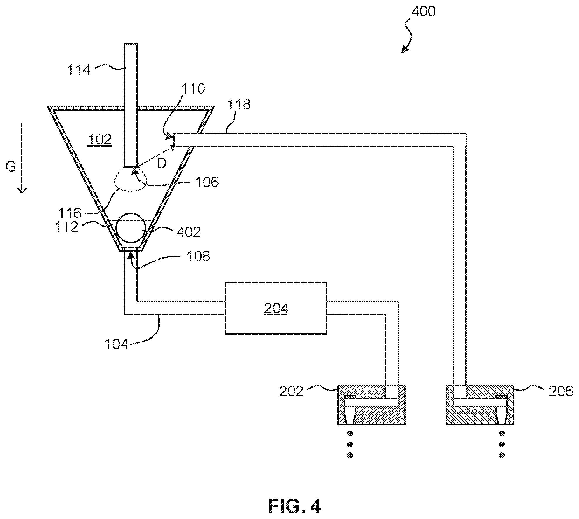
[0057] The analytical process performed at the target microfluidic network 204 may include a nucleic acid testing process. For example, with reference to the example device 400 shown in FIG. 4, a biological sample, such as a DNA/RNA sample, may be concentrated around a permanent magnet 402 located within a chamber 102 or embedded in a wall of the chamber 102. Features and aspects of the other devices and systems described herein may be used with the device 400 and vice versa. Like reference numerals denote like elements and description of like elements is not repeated here.
[0058] Fluid provided to the inlet channel 114 may include a DNA/RNA sample mixed with paramagnetic microbeads. A microbead surface has physical or chemical affinity to an analyte of interest, for example, a DNA molecule or a particular protein. Negative pressure is applied to a negative pressure port 110 to draw droplets 116 of the fluid into the chamber 102 to interact with the magnet 402. The magnet attracts the paramagnetic microbeads from the other material of the sample, thus concentrating the analyte. The fluid 112 may be provided with a residence time near the magnet 402, enhancing concentration.
[0059] The negative pressure may be ceased once sufficient analyte is collected. Then, the fluid 112 may be drawn from the chamber 102 by activation of a droplet ejector 202 communicating with a fluid outlet 108 of the chamber 102.
[0060] Subsequently, another fluid may be provided to the inlet channel 114 and brought into the chamber 102 to release the concentrated analyte from the magnet 402. Such a fluid may include an elution buffer that elutes the analyte and allows the analyte to be drawn into the target microfluidic network 204 to undergo a nucleic acid testing process implemented by the target microfluidic network 204.
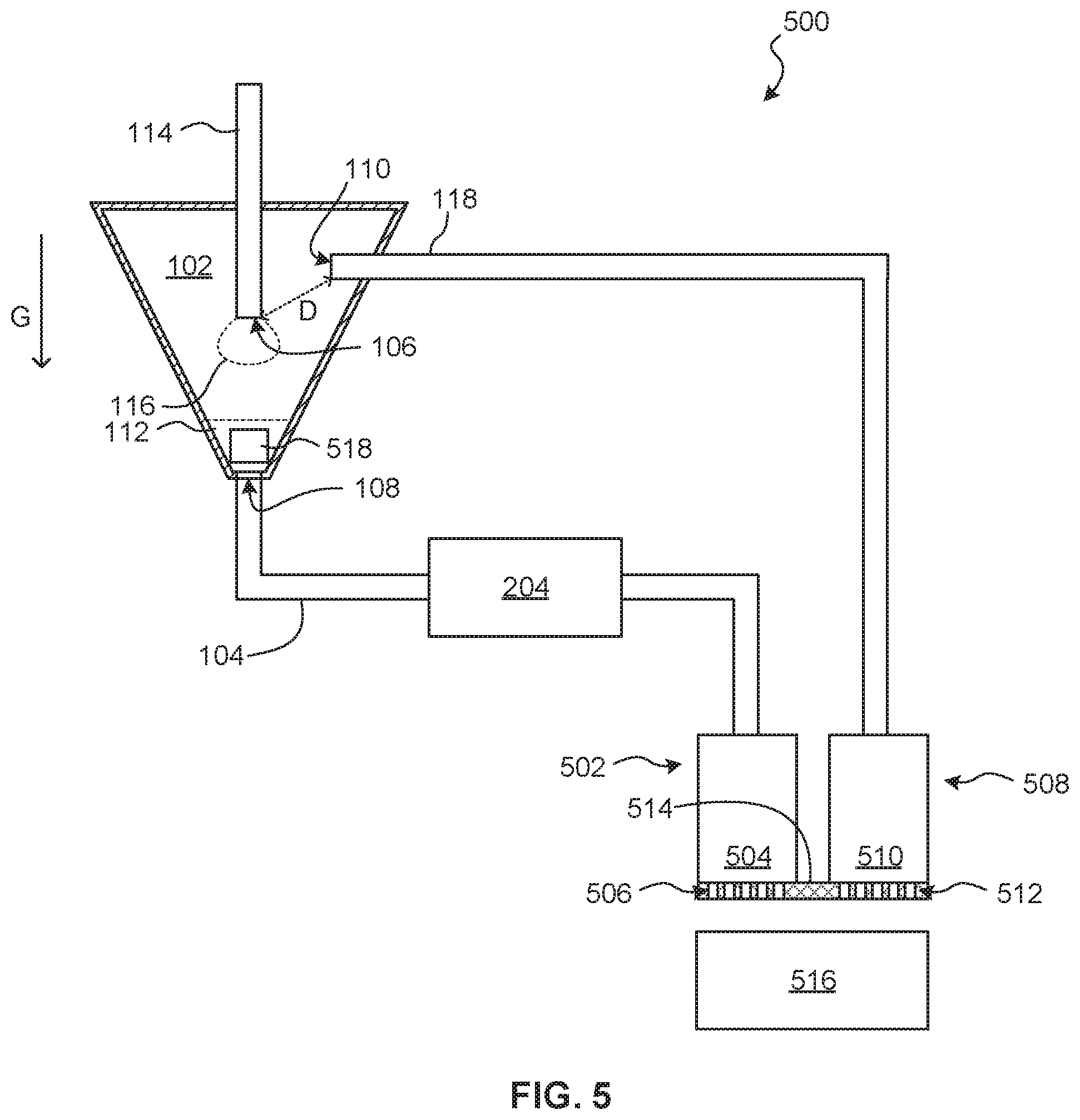
[0061] FIG. 5 shows an example device 500. Features and aspects of the other devices and systems described herein may be used with the device 500 and vice versa. Like reference numerals denote like elements and description of like elements is not repeated here.
[0062] The device 500 includes a first ejection unit 502 connected to a downstream end of a downstream microfluidic channel 104 that communicates with a fluid outlet 108 of a chamber 102. The first ejection unit 502 includes a fluid reservoir 504 and a droplet ejector 506 or array thereof that is fed with fluid by the fluid reservoir 504. The fluid reservoir 504 may be primed with a fluid that is ejected to generate a negative pressure in the downstream microfluidic channel 104 to draw fluid 112 from the chamber 102 through a target microfluidic network 204.
[0063] The device 500 includes a second ejection unit 508 connected to a downstream end of a negative pressure channel 118 that communicates with a negative-pressure port 110 of the chamber 102. The second ejection unit 508 includes a fluid reservoir 510 and a droplet ejector 512 or array thereof that is fed with fluid by the fluid reservoir 510. The fluid reservoir 510 may be primed with a fluid that is ejected to generate a negative pressure in the negative pressure channel 118 to draw fluid droplets 116 into chamber 102 via a fluid 106.
[0064] The droplet ejectors 506, 512 may be formed at the same semiconductor substrate 514. Alternatively, the droplet ejectors 506, 512 may be formed at different semiconductor substrates that may be physically joined by, for example, being molded into a single flat package (e.g., semiconductor slivers that are epoxy-molded together). Alternatively still, the droplet ejectors 506, 512 may be provided in two separate packages or printheads.
[0065] The droplet ejectors 506, 512 may eject to a waste area 516, such as an absorbent material.
[0066] In an example application, which also applies to the other devices described herein, the device 500 may be used for reagent rehydration. A dried reagent 518, such as a solid or powdered material, may be located in the chamber 102. Rehydration fluid, such as water, may be drawn into the chamber 102 by activating the second ejection unit 508 to provide a negative pressure in the chamber 102, thereby causing droplets of rehydration fluid to be pulled into the chamber 102 from the fluid inlet 106. The rehydration fluid collects at the bottom of the chamber 102 and rehydrates the dried reagent 518. When rehydration is complete, the resulting fluid reagent may be draw into the target microfluidic network 204 by activation of the first ejection unit 502. The second ejection unit 508 may be stopped so as to not resist fluid movement out of the outlet 108 of the chamber 102. Alternatively, the second ejection unit 508 may be run until its driving fluid is completely ejected thereby releasing the partial vacuum at the negative-pressure port 110 with no sensor or other intervention required.
[0067] The dried reagent 518 may be a freeze-dried PCR master mix for use at the target microfluidic network 204 that implements a nucleic acid testing process.
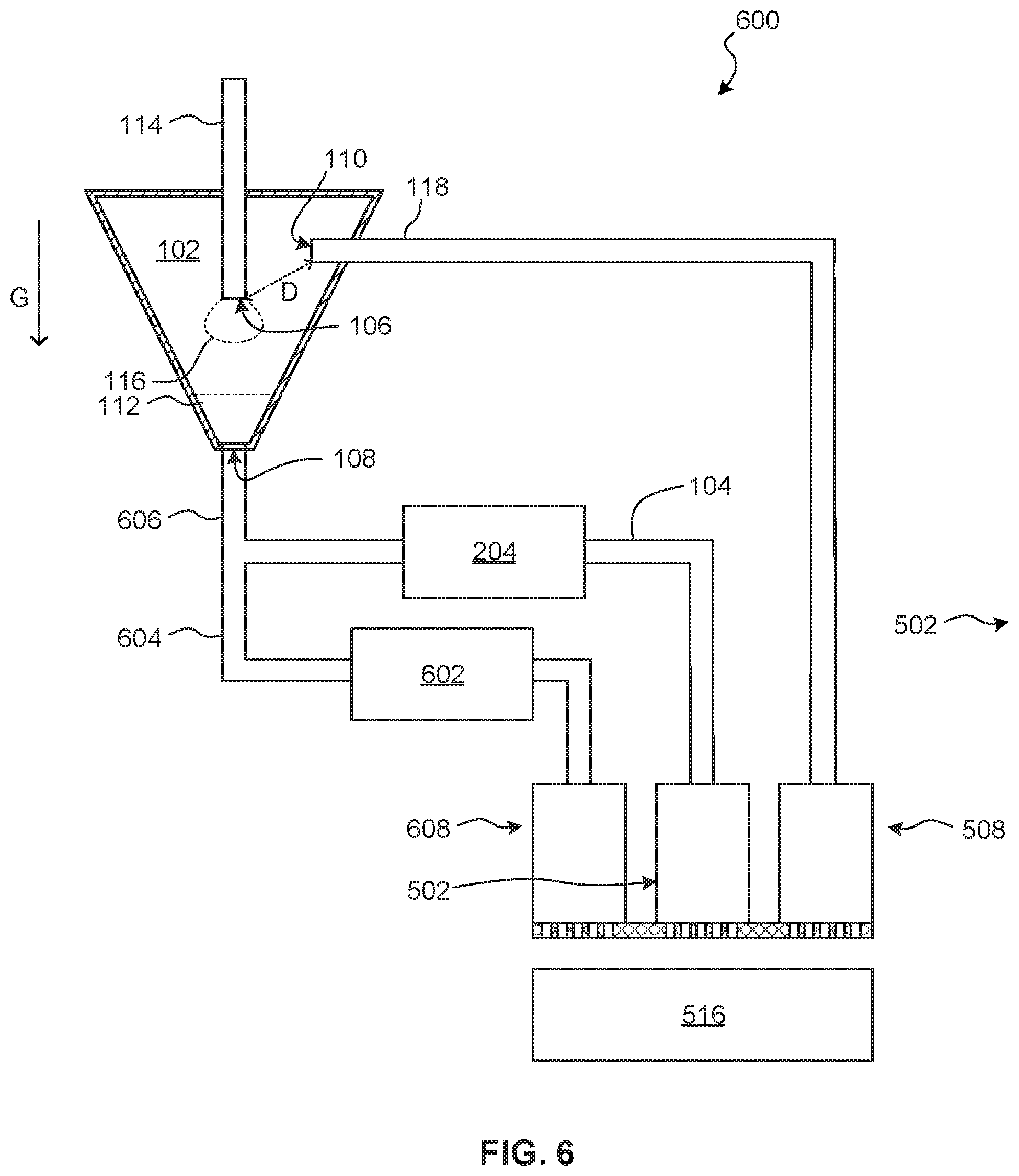
[0068] FIG. 6 shows an example device 600. Features and aspects of the other devices and systems described herein may be used with the device 600 and vice versa. Like reference numerals denote like elements and description of like elements is not repeated here.
[0069] A plurality of target microfluidic networks 204, 602 may be provided downstream of a chamber 102 that is provided fluid through vacuum induction of fluid droplets 116 by a negative-pressure port 110. The target microfluidic networks 204, 602 may be arranged in parallel. For example, each target microfluidic networks 204, 602 may be may communicate with the chamber via a respective downstream microfluidic channel 104, 604 that extend from a common channel 606 that connects to an outlet of the chamber 102.
[0070] Fluid may be selectively drawn through the target microfluidic networks 204, 602 by selective activation of respective downstream ejection units 502, 608.
[0071] In one example application, the target microfluidic networks 204, 602 may be used to perform different nucleic acid testing processes (e.g., different heating cycle programs, etc.) to the same sample collected at the chamber 102. In another example, the target microfluidic networks 204, 602 may be used to perform the same nucleic acid testing process to different fluids drawn from the chamber 102. That is, an analyte at different concentrations may be drawn into the target microfluidic networks 204, 602 at different times.
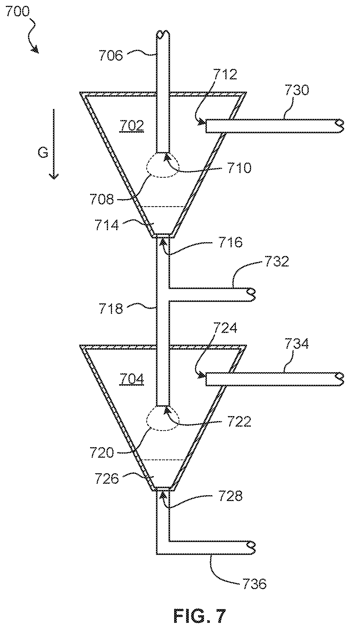
[0072] FIG. 7 shows an example device 700. Features and aspects of the other devices and systems described herein may be used with the device 700 and vice versa. Like reference numerals denote like elements and description of like elements is not repeated here.
[0073] A plurality of chambers 702, 704 may be vertically arranged. Fluid may be provided to an inlet channel 706 at an upper chamber 702. Fluid droplets 708 may be drawn into the upper chamber 702 through a fluid inlet 710 by negative pressure applied to the chamber 702 via an upper negative-pressure port 712. Droplets collect as fluid 714 at the bottom of the upper chamber 702 near an upper fluid outlet 716. The upper fluid outlet 716 communicates with an inlet channel 718 at a lower chamber 704. Fluid droplets 720 may be drawn into the lower chamber 704 through a fluid inlet 722 that communicates with the inlet channel 718 by negative pressure applied to the chamber 704 via a lower negative-pressure port 724. Droplets collect as fluid 726 at the bottom of the lower chamber 704 near a lower fluid outlet 728.
[0074] Control of the device 700 may be effected by selectively applying negative pressure to the upper negative-pressure port 712, upper fluid outlet 716, lower negative-pressure port 724, and lower fluid outlet 728, by respective channels 730, 732, 734, 736. Negative pressure may be applied to the channels 730, 732, 734, 736 using droplet ejectors.
[0075] For example, a DNA/RNA sample may be drawn into the upper chamber 702 to be concentrated by providing a fluid containing the DNA/RNA sample to the inlet channel 706 and by applying negative pressure to the channel 730. A magnet may be provided in the upper chamber 702 to assist in concentration, as described elsewhere herein. The fluid may include a lysis buffer. After concentration, the remaining fluid may be drawn through the channel 732 to waste. The sample in the upper chamber 702 may be washed. The concentrated sample may then be eluted from the upper chamber 702 and drawn into the lower chamber 704 by applying a negative pressure to the channel 734. Once accumulated in the lower chamber 704, the prepared sample may be metered out to a target microfluidic network connected to the channel 736 by applying a negative pressure to the channel 736. The target microfluidic network may then be controlled to perform a nucleic acid testing process on the sample.
[0076] FIG. 8 shows an example system 800. Features and aspects of the other devices and systems described herein may be used with the system 800 and vice versa. Like reference numerals denote like elements and description of like elements is not repeated here.
[0077] The system 800 includes a cartridge 802 including a chamber 102 or arrangement of chambers, as discussed elsewhere herein, including a negative-pressure port to receive a negative pressure to draw droplets of fluid into the chamber 102 for use by a downstream target microfluidic network. Such components may be contained within a cartridge housing 804.
[0078] The cartridge 802 further includes a signal interface 806 at the housing 804. The signal interface 806 is electrically connected to a droplet ejector that applies a negative pressure to the chamber 102. The signal interface 806 may include an electrical contact.
[0079] The system 800 further includes an analysis device 808. The analysis device 808 includes a processor 810 installed within a housing 812. The processor 810 is connected to an interface 814 that may include an electrical contact. The interface 814 provides for communications between the processor 810 and the signal interface 806 of the cartridge 802. The analysis device 808 may allow for user control of a process implemented by a cartridge 802. The analysis device 808 may be installed at a lab or other location in an upright orientation.
[0080] The housing 804 of the cartridge 802 includes a feature 816 shaped to position a fluid outlet of the chamber 102 below a fluid inlet of the chamber 102 relative to a force of gravity G when the feature 816 is mated with a complementary feature 818 at the housing 812 of the analysis device 808. The features 816, 818 may include a mating groove and ridge, for example.
[0081] The cartridge 802 is removably mechanically connected to the analysis device 808 by way of the mating features 816, 818. Further, when the analysis device 808 is upright, the mating features 816, 818 force the cartridge 802 to be connected in the correct orientation relative to a force of gravity G, so that the chamber 102 may function as described herein.
[0082] When connected, the signal interface 806 of the cartridge 802 may receive a signal from the processor 810 via the interface 814 of the analysis device 808, and such signal may drive a droplet ejector of the cartridge 802 to apply the negative pressure to the chamber 102 to operate the chamber 102 as described elsewhere herein.
[0083] FIG. 9 shows an example device 100 installed at a centrifuge 900. Any of the devices and systems described herein may be so installed at a rotating disc or other rotational element of a centrifuge 900. The device 100 is oriented so that its chamber 102 narrows in a direction of a centrifugal force F generated by rotation of the centrifuge 900. That is, the chamber 102 may be shaped and oriented with respect to the centrifuge 900 to collect fluid at its fluid outlet 108 under centrifugal force F. In this way, centrifugal force F may be used to mimic the effect of gravity. Other features and aspects of the device 100 may be as described elsewhere herein.
[0084] As should be apparent from the above, the techniques described herein allow for vacuum controlled fluid manipulations at microfluidic scale. A mesofluidic chamber is provided with a negative pressure port that may be controlled by a microfluidic droplet ejector without direct human intervention.
[0085] It should be recognized that features and aspects of the various examples provided above can be combined into further examples that also fall within the scope of the present disclosure. In addition, the figures are not to scale and may have size and shape exaggerated for illustrative purposes.
* * * * *
D00000
D00001
D00002
D00003
D00004
D00005
D00006
D00007
D00008
D00009
XML
uspto.report is an independent third-party trademark research tool that is not affiliated, endorsed, or sponsored by the United States Patent and Trademark Office (USPTO) or any other governmental organization. The information provided by uspto.report is based on publicly available data at the time of writing and is intended for informational purposes only.
While we strive to provide accurate and up-to-date information, we do not guarantee the accuracy, completeness, reliability, or suitability of the information displayed on this site. The use of this site is at your own risk. Any reliance you place on such information is therefore strictly at your own risk.
All official trademark data, including owner information, should be verified by visiting the official USPTO website at www.uspto.gov. This site is not intended to replace professional legal advice and should not be used as a substitute for consulting with a legal professional who is knowledgeable about trademark law.