Knife Lockout Wedge
Eisinger; Joseph
U.S. patent application number 16/890150 was filed with the patent office on 2021-01-28 for knife lockout wedge. The applicant listed for this patent is Covidien LP. Invention is credited to Joseph Eisinger.
| Application Number | 20210022731 16/890150 |
| Document ID | / |
| Family ID | 1000004902854 |
| Filed Date | 2021-01-28 |


| United States Patent Application | 20210022731 |
| Kind Code | A1 |
| Eisinger; Joseph | January 28, 2021 |
KNIFE LOCKOUT WEDGE
Abstract
A surgical stapling device includes an adaptor assembly and a reload assembly supported on a distal end portion of the adaptor assembly. The reload assembly includes a shell housing, a staple cartridge supporting staples, a staple pusher, a staple actuator, a knife carrier, and a locking member. The staple pusher is movable from a retracted position to an advanced position to eject the staples from the staple cartridge. The staple actuator is movable from a retracted position to an advanced position to move the staple pusher from its retracted position to its advanced position. The knife carrier is movable between a retracted position and an advanced position. The locking member is supported on the knife carrier. The locking member is configured to engage the staple actuator in its advanced position while engaging the knife carrier in its retracted position such that the locking member inhibits re-advancement of the knife carrier.
| Inventors: | Eisinger; Joseph; (Northford, CT) | ||||||||||
| Applicant: |
|
||||||||||
|---|---|---|---|---|---|---|---|---|---|---|---|
| Family ID: | 1000004902854 | ||||||||||
| Appl. No.: | 16/890150 | ||||||||||
| Filed: | June 2, 2020 |
Related U.S. Patent Documents
| Application Number | Filing Date | Patent Number | ||
|---|---|---|---|---|
| 62879072 | Jul 26, 2019 | |||
| Current U.S. Class: | 1/1 |
| Current CPC Class: | A61B 17/0686 20130101; A61B 2017/07228 20130101; A61B 2017/07285 20130101; A61B 2017/07271 20130101 |
| International Class: | A61B 17/068 20060101 A61B017/068 |
Claims
1. A surgical stapling device comprising: an adaptor assembly having a proximal end portion and a distal end portion; and a reload assembly supported on the distal end portion of the adaptor assembly, the reload assembly including: a shell housing including an outer housing portion and an inner housing portion, the inner and outer housing portions defining an annular cavity; a staple cartridge supporting a plurality of staples; a staple pusher supported within the annular cavity and movable from a retracted position to an advanced position to eject the plurality of staples from the staple cartridge; a staple actuator supported within the annular cavity and movable from a retracted position to an advanced position to move the staple pusher from its retracted position to its advanced position; a knife carrier supported within the through bore and movable between a retracted position and an advanced position, the knife carrier supporting a knife; and a locking member slidably supported on the knife carrier, the locking member configured to engage the staple actuator in its advanced position while engaging the knife carrier in its retracted position such that the locking member inhibits re-advancement of the knife carrier.
2. The surgical stapling device according to claim 1, wherein the knife carrier has a proximal portion defining a circumferential groove configured to anchor the locking member thereagainst, when the locking member engages the staple actuator is in its advanced position.
3. The surgical stapling device according to claim 1, wherein the locking member has an annular profile.
4. The surgical stapling device according to claim 1, wherein the locking member has a break for radial flexing thereof.
5. The surgical stapling device according to claim 1, wherein the locking member includes proximal and distal portions, the proximal portion having an engaging surface extending radially inward and a proximal surface defining an acute angle with the engaging surface.
6. The surgical stapling device according to claim 5, wherein the distal portion of the locking member includes a hook portion.
7. The surgical stapling device according to claim 6, wherein the knife carrier includes a plurality of longitudinally extending body portions, wherein adjacent longitudinally extending body portions defines a slot.
8. The surgical stapling device according to claim 7, wherein the locking member includes an axial guide configured to be slidably received in the slot of the knife carrier.
9. The surgical stapling device according to claim 7, wherein each longitudinally extending body portion includes a proximal portion defining a groove and a tapered portion proximal of the groove.
10. The surgical stapling device according to claim 9, wherein the tapered portion of the longitudinally extending body portion is configured to slidably engage the engaging surface of the locking member.
11. The surgical stapling device according to claim 9, wherein the groove of the knife carrier includes a distal wall and a proximal wall, the hook portion of the locking member includes an engaging surface configured to slide over the distal wall of the groove.
12. The surgical stapling device according to claim 11, wherein the proximal surface of the locking member is configured to engage the proximal wall of the groove when the locking member engages the staple actuator in its advanced position.
13. A surgical stapling device comprising: a reload assembly including: a shell housing defining an annular cavity; a staple cartridge supporting a plurality of staples; a staple pusher supported within the annular cavity and movable from a retracted position to an advanced position to eject the plurality of staples from the staple cartridge; a staple actuator supported within the annular cavity and engaged with the staple pusher, the staple actuator movable from a retracted position to an advanced position to move the staple pusher from its retracted position to its advanced position, the staple actuator and the staple pusher defining a through bore; a knife carrier supported within the through bore and movable between a retracted position and an advanced position, the knife carrier including a proximal portion defining a notch, the knife carrier supporting a knife; and a locking member slidably supported on the knife carrier, the locking member including an annular body having a proximal end configured to be anchored against the notch of the knife carrier and a distal end configured to engage the staple actuator such that when the staple actuator is in its advanced position and the knife carrier is in its retracted position, the locking member inhibits re-advancement of the knife carrier.
14. The surgical stapling device according to claim 13, wherein the locking member defines a break for radial flexing thereof.
15. The surgical stapling device according to claim 13, wherein a distal end of the locking member is configured to slide over the notch of the knife carrier.
16. The surgical stapling device according to claim 15, wherein the locking member includes axial guide configured to limit the locking member to an axial movement relative to the knife carrier.
17. The surgical stapling device according to claim 15, wherein the proximal end of the locking member includes an engaging surface extending radially inward, the engaging surface configured to slidably engage a tapered portion of the proximal portion of the knife carrier.
18. The surgical stapling device according to claim 13, wherein the distal end of the locking member includes a hook portion.
19. The surgical stapling device according to claim 18, wherein the distal end of the hook portion is tapered.
Description
CROSS-REFERENCE TO RELATED APPLICATIONS
[0001] This application claims the benefit of and priority to U.S. Provisional Patent Application Ser. No. 62/879,072 filed Jul. 26, 2019, the entire disclosure of which is incorporated by reference herein.
BACKGROUND
Technical Field
[0002] The disclosure is directed to circular stapling devices and, more particularly, to reload assemblies for circular stapling devices with structure to retain a knife carrier of the reload assembly in a retracted position after the circular stapling device is fired.
Background of Related Art
[0003] Conventional circular stapling devices include an elongate body and a shell or reload assembly that is supported on a distal portion of the elongate body. The reload assembly includes a shell housing, a staple cartridge supported on the shell housing having a plurality of staples, a pusher assembly, a knife defining a cylindrical cavity, and a knife carrier that supports the knife. The pusher assembly includes an annular pusher and a staple pushing member that is engaged with the annular pusher and is movable to move the staple pushing member to eject staples from the staple cartridge. The knife carrier is movable to advance the knife through the staple cartridge to core or cut tissue.
[0004] After a circular stapling device has been operated to staple and cut tissue, the knife carrier and the knife are retracted to withdraw the knife into the shell housing. This serves two purposes. The first purpose is to move the knife to a position to allow removal of a tissue donut from within the cavity defined by the knife. The second purpose is to position the knife in a location recessed within the shell housing to avoid injury to a clinician during manipulation and disposal of the reload assembly.
[0005] A continuing need exists in the art for a reload assembly that includes improved structure for retaining the knife/knife carrier in a retracted position.
SUMMARY
[0006] In accordance with an embodiment of the disclosure, a surgical stapling device includes an adaptor assembly having a proximal end portion and a distal end portion, and a reload assembly supported on the distal end portion of the adaptor assembly. The reload assembly includes a shell housing, a staple cartridge supporting a plurality of staples, a staple pusher, a staple actuator, a knife carrier, and a locking member. The shell housing includes an outer housing portion and an inner housing portion. The inner and outer housing portions define an annular cavity. The staple pusher is supported within the annular cavity and movable from a retracted position to an advanced position to eject the plurality of staples from the staple cartridge. The staple actuator is supported within the annular cavity and movable from a retracted position to an advanced position to move the staple pusher from its retracted position to its advanced position. The knife carrier is supported within the through bore and movable between a retracted position and an advanced position. The knife carrier supports a knife. The locking member is slidably supported on the knife carrier. The locking member is configured to engage the staple actuator in its advanced position while engaging the knife carrier in its retracted position such that the locking member inhibits re-advancement of the knife carrier.
[0007] In an embodiment, the knife carrier may have a proximal portion defining a circumferential groove configured to anchor the locking member thereagainst when the locking member engages the staple actuator is in its advanced position.
[0008] In another embodiment, the locking member may have an annular profile.
[0009] In yet another embodiment, the locking member may have a break for radial flexing thereof.
[0010] In yet another embodiment, the locking member may include proximal and distal portions. The proximal portion may have an engaging surface extending radially inward and a proximal surface defining an acute angle with the engaging surface.
[0011] In an embodiment, the distal portion of the locking member may include a hook portion.
[0012] In another embodiment, the knife carrier may include a plurality of longitudinally extending body portions. Adjacent longitudinally extending body portions may define a slot.
[0013] In yet another embodiment, the locking member may include an axial guide configured to be slidably received in the slot of the knife carrier.
[0014] In an embodiment, each longitudinally extending body portion may include a proximal portion defining a groove and a tapered portion proximal of the groove.
[0015] In another embodiment, the tapered portion of the longitudinally extending body portion may be configured to slidably engage the engaging surface of the locking member.
[0016] In another embodiment, the groove of the knife carrier may include a distal wall and a proximal wall. The hook portion of the locking member may include an engaging surface configured to slide over the distal wall of the groove.
[0017] In another embodiment, the proximal surface of the locking member may be configured to engage the proximal wall of the groove when the locking member engages the staple actuator in its advanced position.
[0018] In accordance with another embodiment of the disclosure, a surgical stapling device includes a reload assembly including a shell housing defining an annular cavity, a staple cartridge supporting a plurality of staples, a staple pusher, a staple actuator, a knife carrier, and a locking member. The staple pusher is supported within the annular cavity and movable from a retracted position to an advanced position to eject the plurality of staples from the staple cartridge. The staple actuator is supported within the annular cavity and engaged with the staple pusher. The staple actuator is movable from a retracted position to an advanced position to move the staple pusher from its retracted position to its advanced position. The staple actuator and the staple pusher define a through bore. The knife carrier is supported within the through bore and movable between a retracted position and an advanced position. The knife carrier includes a proximal portion defining a notch. The knife carrier supports a knife. The locking member is slidably supported on the knife carrier. The locking member includes an annular body having a proximal end configured to be anchored against the notch of the knife carrier and a distal end configured to engage the staple actuator such that when the staple actuator is in its advanced position and the knife carrier is in its retracted position, the locking member inhibits re-advancement of the knife carrier.
[0019] In an embodiment, a distal end of the locking member may be configured to slide over the notch of the knife carrier.
BRIEF DESCRIPTION OF THE DRAWINGS
[0020] Various aspects and features of the disclosure are described hereinbelow with reference to the drawings wherein like numerals designate identical or corresponding elements in each of the several views and:
[0021] FIG. 1 is a side perspective view of a circular stapling device including an exemplary embodiment of a disclosed reload assembly with the circular stapling device in a clamped position;
[0022] FIG. 2 is a side perspective view of the reload assembly of the circular stapling device shown in FIG. 1;
[0023] FIG. 3 is a perspective exploded view of the reload assembly shown in FIG. 2;
[0024] FIG. 4 is a side view of the reload assembly of the circular stapling device shown in FIG. 1;
[0025] FIG. 5 is a perspective view of the reload assembly from a proximal end thereof;
[0026] FIG. 6 is an enlarged view of the indicated area of detail shown in FIG. 3;
[0027] FIG. 7 is a perspective view of a locking member of the reload assembly shown in FIG. 1;
[0028] FIG. 8 is a cross-sectional view taken along section line 8-8 of FIG. 1 with the reload assembly in a pre-fired state;
[0029] FIG. 9 is an enlarged view of the indicated area of detail shown in FIG. 8;
[0030] FIG. 10 is a cross-sectional view taken along section line 8-8 of FIG. 1 with the reload assembly in a fired state and a staple actuator driver in a retracted position;
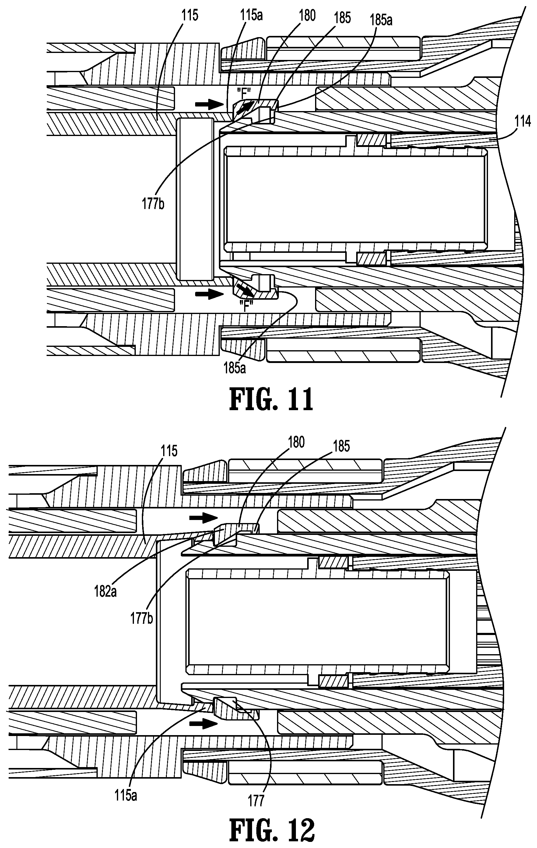
[0031] FIGS. 11 and 12 are cross-sectional views taken along section line 8-8 of FIG. 1 with the reload assembly in a fired state and a knife carrier driver moving toward its advanced position;
[0032] FIG. 13 is a cross-sectional view taken along section line 8-8 of FIG. 1 with the reload assembly in a fired state and the knife carrier driver moving towards the advanced position such that the knife carrier driver engages the knife carrier;
[0033] FIG. 14 is a cross-sectional view taken along section line 8-8 of FIG. 1 with the reload assembly in a fired state and the knife carrier in the advanced position;
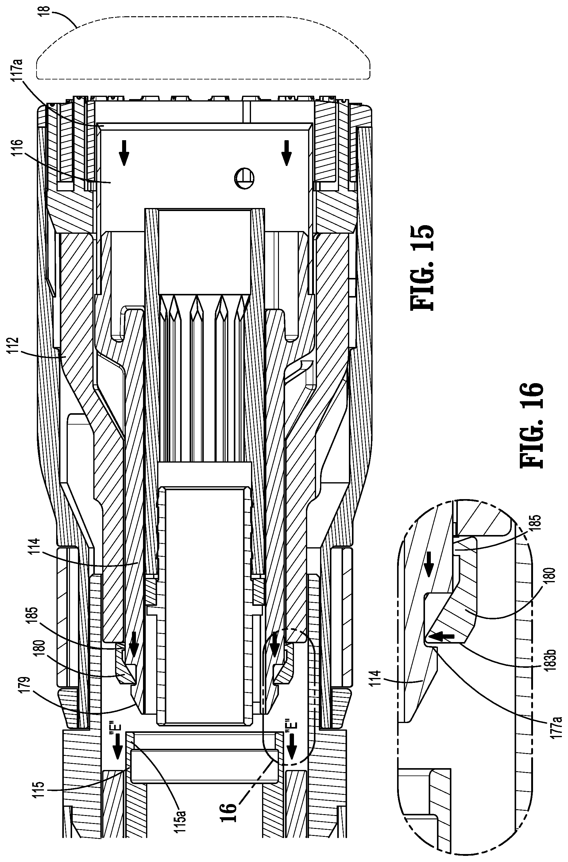
[0034] FIG. 15 is a cross-sectional view taken along section line 8-8 of FIG. 1 with the reload assembly in a fired state and the knife carrier in a locked position by a locking member; and
[0035] FIG. 16 is an enlarged view of the indicated area of detail shown in FIG. 15.
DETAILED DESCRIPTION
[0036] The disclosed reload assembly for a circular stapling device will now be described in detail with reference to the drawings in which like reference numerals designate identical or corresponding elements in each of the several views. However, it is to be understood that the disclosed embodiments are merely exemplary of the disclosure and may be embodied in various forms. Well-known functions or constructions are not described in detail to avoid obscuring the disclosure in unnecessary detail. Therefore, specific structural and functional details disclosed herein are not to be interpreted as limiting, but merely as a basis for the claims and as a representative basis for teaching one skilled in the art to variously employ the disclosure in virtually any appropriately detailed structure. In addition, directional terms such as front, rear, upper, lower, top, bottom, distal, proximal, and similar terms are used to assist in understanding the description and are not intended to limit the disclosure.
[0037] In this description, the term "proximal" is used generally to refer to that portion of the device that is closer to a clinician, while the term "distal" is used generally to refer to that portion of the device that is farther from the clinician. In addition, the term "clinician" is used generally to refer to medical personnel including doctors, nurses, and support personnel.
[0038] FIGS. 1 and 2 illustrate a circular stapling device 10 including an exemplary embodiment of the disclosed reload assembly shown generally as a reload assembly 100. The circular stapling device 10 includes a handle assembly 12, an elongate body or adaptor assembly 14, the reload assembly 100, and an anvil assembly 18 that is supported for movement in relation to the reload assembly 100 between spaced and approximated positions as is known in the art. In embodiments, the reload assembly 100 includes a proximal portion 102 that is releasably coupled to a distal portion 14a of the adaptor assembly 14. The handle assembly 12 includes a stationary grip 22 that supports actuation buttons 24 for controlling operation of various functions of the circular stapling device 10 including approximation of the reload and anvil assemblies 100, 18, respectively, firing of staples from the reload assembly 100, and cutting or coring of tissue as described in further detail below.
[0039] The circular stapling device 10 is illustrated as an electrically powered stapling device including an electrically powered handle assembly 12 that may support one or more batteries (not shown). The adaptor assembly 14 is in the form of an adaptor assembly that translates power from the handle assembly 12 to the reload and anvil assemblies 100, 18, respectively. The adaptor assembly 14 further includes a knife carrier driver 115 (FIG. 8) that interacts with a knife carrier 114 (FIG. 3) to move the knife carrier 114 within a shell housing 110 (FIG. 3), and a staple actuator driver 195 (FIG. 8) that interacts with a staple actuator 112 (FIG. 3) to move the staple actuator 112 within the shell housing 110. Examples of electrically powered stapling devices can be found in U.S. Pat. Nos. 9,055,943, 9,023,014, and U.S. Publication Nos. 2018/0125495, and 2017/0340351. Alternately, it is envisioned that the disclosure could also be incorporated into a manually powered stapling device as disclosed in, e.g., U.S. Pat. No. 7,303,106 (the '106 Patent), or a stapling device that is configured for use with a robotic system as disclosed in, e.g., U.S. Pat. No. 9,962,159, that does not include a handle assembly. The disclosure of each of these patents and publications is incorporated by reference herein in its entirety.
[0040] FIGS. 2 and 3 illustrate the reload assembly 100 which includes the shell housing 110, the staple actuator 112, a staple pushing member 112a, the knife carrier 114, an annular knife 116 supported on the knife carrier 114, a staple cartridge 118, and a plurality of staples 120 supported within the staple cartridge 118. The staple actuator 112 includes a body 113 that is also received about the inner housing portion 142 of the shell housing 110 and is movable within the shell housing 110 from a retracted position to an advanced position. The staple cartridge 118 is annular and defines annular rows of staple pockets 124. Each of the staple pockets 124 supports one of the plurality of staples 120. The staple actuator 112 and the staple pushing member 112a together define a longitudinal through-bore 132 (FIG. 8). The staple actuator 112 has a distal portion that rabuts a proximal portion of the staple pushing member 112a such that distal movement of the staple actuator 112 within the shell housing 110 causes distal movement of the staple pushing member 112a within the shell housing 110. The staple pushing member 112a of the reload assembly 100 has a plurality of fingers 134. Each of the plurality of fingers 134 is received within a respective one of the staple pockets 124 of the staple cartridge 118 and is movable through the respective staple pocket 124 to eject the staples 120 from the staple pockets 124 when the staple pushing member 112a is moved from a retracted position to an advanced position within the shell housing 110.
[0041] With particular reference to FIG. 3, the shell housing 110 includes an outer housing portion 140 and an inner housing portion 142 that are spaced from each other to define an annular cavity 144 (FIG. 3) between the outer and inner housing portions 140 and 142. The staple actuator 112 and the staple pushing member 112a are movable within the annular cavity 144 of the shell housing 110 from a retracted position to an advanced position to eject the staples 120 from the staple cartridge 118 as described in further detail below.
[0042] The annular knife 116 is supported about an outer surface of the knife carrier 114. The annular knife 116 defines a cylindrical cavity 117 and includes a distal cutting edge 117a. In embodiments, the annular knife 116 includes inwardly extending tangs 117b that are received within pockets 114a defined in an outer surface of the knife carrier 114 to secure the annular knife 116 to the knife carrier 114. The knife carrier 114 and annular knife 116 are positioned within the longitudinal through-bore 132 (FIG. 8) of the staple actuator 112 and movable from a retracted position to an advanced position to cut tissue positioned radially inward of the staple cartridge 118 as described in further detail below.
[0043] With continued reference to FIG. 3, the inner housing portion 142 of the shell housing 110 defines a through-bore 150 that receives an anvil shaft (not shown) of the anvil assembly 18. For a more detailed description of an exemplary anvil assembly 18, see, e.g., the '106 Patent. The through-bore 150 has a proximal portion that receives a bushing 152 that defines a through-bore 150a that is coaxial and forms an extension of the through-bore 150 of the inner housing portion 142. In embodiments, the bushing 152 is formed of a high strength material, e.g., metal, to provide added strength to the inner housing portion 142 of the shell housing 110 and includes an annular flange 152a.
[0044] The shell housing 110 includes a proximal portion 158 (FIG. 3) that supports a coupling mechanism 160 that is operable to releasably couple the reload assembly 100 to the adaptor assembly 14 of the circular stapling device 10 (FIG. 1) to allow for removal and replacement of the reload assembly 100 to facilitate reuse of the circular stapling device 10. The coupling mechanism 160 includes a retaining member 162 and a coupling member 164. The coupling member 164 is received about the proximal portion 158 (FIG. 3) of the shell housing 110 and is configured to engage the distal portion 14a (FIG. 1) of the adaptor assembly 14 to couple the reload assembly 100 to the adaptor assembly 14. It is envisioned that other coupling mechanisms can be used to secure the reload assembly 100 to the adaptor assembly 14. Alternatively, the reload assembly 100 can be non-removably secured to the adaptor assembly 14.
[0045] The reload assembly 100 may include an e-prom holder 170 (FIG. 3) that is supported on the shell housing 110 and is configured to support an e-prom (not shown). As is known in the art, an e-prom can communicate with the adaptor assembly 14 to provide information related to characteristics of the reload assembly 10. In some embodiments, the e-prom holder 170 can be received about a distal portion of the bushing 152.
[0046] FIGS. 3-5 illustrate the knife carrier 114 which includes a plurality of spaced longitudinally extending body portions 173 defining a central bore 172. The central bore 172 of the knife carrier 114 receives the inner housing portion 142 of the shell housing 110 such that the knife carrier 114 is movable about the inner housing portion 142 of the shell housing 110 between a retracted position (FIG. 8) and an advanced position (FIG. 14). The longitudinally extending body portions 173 of the knife carrier 114 defines slots 176 that receive guide portions (not shown) of the shell housing 110 to limit the knife carrier 114 to longitudinal movement. The knife carrier 114 includes hook members 178 (FIG. 6) that are positioned to engage the knife carrier driver 115 as described in further detail below to move the knife carrier 114 from its retracted position to its advanced position. Each of the hook members 178 includes an engagement surface 177a (FIG. 9) and supports a locking member 180. In embodiments, the locking member 180 is initially positioned adjacent or in engagement with the hook members 178. In embodiments, the locking member 180 is formed of a resilient material that can be radially deformed to be removably supported on the knife carrier 114, but is sufficiently rigid to inhibit re-advancement of the knife carrier 114 as described below.
[0047] FIGS. 6 and 7 illustrate the locking member 180 of the reload assembly 100 that includes a body 182 having an annular profile. The locking member 180 is received about a proximal portion of the knife carrier 114. In particular, the locking member 180 includes at least one axial guide 184 configured to be slidably received in the slot 176 (FIG. 3) of the knife carrier 114 to inhibit rotation of the locking member 180 in relation to the knife carrier 114 in order to limit the knife carrier 114 to axial movement within the shell housing 110. In embodiments, the body 182 of the locking member 180 may define a break 198 to allow for radial flexing of the body 182 to facilitate placement of the locking member 180 in a friction fit manner about the knife carrier 114.
[0048] With continued reference to FIGS. 6 and 7, the body 182 of the locking member 180 includes a proximal portion 182a and a distal portion 182b. The proximal portion 182a includes an engaging surface 183a that extends radially inward to facilitate slidable engagement with a tapered surface 179 (FIG. 6) of the hook member 178 of the knife carrier 114. The proximal portion 182a further includes a distal surface 183b substantially orthogonal to a longitudinal axis "L-L" (FIG. 6) defined by the locking member 180. The distal surface 183b is configured to engage the engagement surface 177a (FIG. 9) of the circumferential groove 177 of the knife carrier 114. The engagement surface 177a may also be substantially orthogonal to the longitudinal axis "L-L". The distal portion 182b of the locking member 180 includes a hook portion 185 configured to be received in the circumferential groove 177 of the knife carrier 114. In addition, the hook portion 185 further include a distal surface 185a (FIG. 9) defining an acute angle with respect to the longitudinal axis "L-L" in order to enable the hook portion 185 to slide over a distal wall 177b (FIG. 9) of the circumferential groove 177 when the locking member 180 is displaced distally, as will be described below.
[0049] FIGS. 8 and 9 illustrate the staple actuator 112 which includes a body 113 that is also received about the inner housing portion 142 (FIG. 3) of the shell housing 110 and is movable from a retracted position (FIG. 8) to an advanced position (FIG. 10) in response to movement of a staple actuator driver 195 from its retracted position to its advanced position. The body 113 defines a plurality of guide slots 113a (FIG. 3). The guide slots 113a of the staple actuator 112 receive the guide members (not shown) of the shell housing 110 to limit the staple actuator 112 to longitudinal movement within the shell housing 110.
[0050] FIGS. 8 and 9 illustrate the reload assembly 100 in a pre-fired condition with the knife carrier 114 and the staple actuator 112 of the reload assembly 100 (FIG. 3) in retracted positions and the locking member 180 in an unlatched position located proximally of the distal wall 177b of the circumferential groove 177 of the knife carrier 114. When the knife carrier 114 and the staple actuator 112 are in pre-fired retracted positions, the hook portion 185 of the locking member 180 is disposed in the circumferential groove 177 of the knife carrier 114 such that the engagement surface 177a of the circumferential groove 177 is proximal of the hook portion 185 of the locking member 180. At this time, the engaging surface 183a (FIG. 7) of the locking member 180 is in an abutting relation with the tapered surface 179 (FIG. 6) of the hook member 178 of the knife carrier 114.
[0051] FIG. 10 illustrates the reload assembly 100 as the staple actuator 112 is moved to the advanced position. As the staple actuator 112 moves distally within the shell housing 110 to the advanced position by a staple actuator driver 119, the staple pushing member 112a is moved distally in the direction indicated by arrows "A" to advance the plurality of fingers 134 of the staple pushing member 112a through the staple pockets 124 (FIG. 3) of the staple cartridge 118 to eject the staples 120 (FIG. 3) into the anvil assembly 18 (shown in phantom). As illustrated, the annular knife 116 secured to the knife carrier 114 remains stationary at this time. After the staple actuator 112 is moved to the advanced position, the staple actuator driver 119 is moved from its advanced position to its retracted position in the direction of arrows "B", while the staple actuator 112 remains in the advanced position. At this time, the engaging surface 183a (FIG. 7) of the locking member 180 remains in an abutting relation to the tapered surface 179 (FIG. 6) of the hook member 178 of the knife carrier 114, and the hook portion 185 of the locking member 180 remains within the circumferential groove 177 of the knife carrier 114.
[0052] FIGS. 11 and 12 illustrate the reload assembly 100 as the knife carrier driver 115 is moved distally to advance the locking member 180 such that the engaging surface 183a (FIG. 7) of the locking member 180 slides against the tapered surface 179 (FIG. 6) of the hook member 178 of the knife carrier 114 in the direction of arrows "F" and the hook portion 185 of the locking member 180 slides over the distal wall 177b of the knife carrier 114. As discussed hereinabove, the distal surface 185a of the hook portion 185 is slanted such that when the distal surface 185a is pushed against the distal wall 177b of the knife carrier 114, the hook portion 185 slides over the distal wall 177b. As the hook portion 185 is pushed over the circumferential groove 177 of the knife carrier 114, the proximal portion 182a of the locking member 180 is placed within the circumferential groove 177.
[0053] FIG. 13 illustrates the reload assembly 100 as the knife carrier driver 115 is further moved distally in the direction of arrows "C" such that the knife carrier driver 115 pushes the entire locking member 180 over the circumferential groove 177 of the knife carrier 114 to place the locking member 180 on a lateral surface 114c of the knife carrier 114. At this time, a hook portion 115a of the knife carrier driver 115 is received in the circumferential groove 177 of the knife carrier 114. Under such a configuration, distal movement of the knife carrier driver 115 is imparted to the knife carrier 114 for concomitant axial displacement.
[0054] FIG. 14 illustrates the reload assembly 100 as the knife carrier driver 115 is moved to its advanced position. When the knife carrier driver 115 is moved to the advanced position, the axial displacement of the knife carrier driver 115 is imparted to the knife carrier 114 which, in turn, advances the annular knife 116 out of the shell housing 110 and into engagement with the anvil 18 (shown in phantom) to cut tissue. At this time, the hook portion 115a of the knife carrier driver 115 disposed within the circumferential groove 177 of the knife carrier 114 is disposed distal of the locking member 180.
[0055] FIGS. 15 and 16 illustrate the reload assembly 100 as the knife carrier 114 is moved from its advanced position to its retracted position after the reload assembly is fired. When the knife carrier 114 is moved proximally in the direction indicated by arrows "E" towards its retracted position, the annular knife 116 is also moved proximally to a position located within the shell housing 110. In this position, a clinician is protected from inadvertent injury caused by the cutting edge 117a of the annular knife 116. As the knife carrier 114 moves proximally in relation to the staple actuator 112, the hook portion 115a of the knife carrier driver 115 disposed in the circumferential groove 177 of the knife carrier 114 is also displaced proximally until the hook portion 115a is placed in registration with the hook portion 185 of the locking member 180. At this time, the hook portion 185 of the locking member 180 applies inward pressure to the hook portion 115a of the knife carrier driver 115 to relieve the hook portion 115a from the circumferential groove 177 of the knife carrier 114. In particular, as the hook portion 185 of the locking member 180 applies inward pressure to the hook portion 115a of the knife carrier driver 115, a proximal portion of the hook portion 115a bends radially outward to enable the hook portion 115a to slide over the engagement surface 177a of the circumferential groove 177, which allows the knife carrier driver 115 to disengage from the knife carrier 114 when the knife carrier driver 115 is proximally displaced. In this manner, the knife carrier 114 is in the retracted position and the knife carrier driver 115 is displaced away from the knife carrier 114. At this time, the locking member 180 is anchored against the circumferential groove 177 of the knife carrier 114 and the staple actuator 112 to inhibit exposure of the annular knife 116 out of the shell housing 110 by inadvertent actuation of the knife carrier 114. Under such a configuration, the locking member 180 engages the staple actuator 112 in the advanced position such that even when the knife carrier diver 115 is inadvertently actuated, the locking member 180 inhibits transition of the knife carrier 114 to the advanced position. In particular, the hook portion 115a of the knife carrier driver 115 is inhibited from being received in the circumferential groove 177 of the knife carrier 114, thereby inhibiting axial displacement of the knife carrier 114 by the knife carrier driver 115. Once again, this obstructs advancement of the knife carrier 114 to inhibit re-advancement of the annular knife 116 from within the shell housing 110.
[0056] As an alternative to the handle assembly 12 (FIG. 1) configured for manual grasping and manipulation during use, the circular stapling device 10 may alternatively be configured for use with a robotic surgical system wherein the reload assembly 100 is configured to engage a robotic arm of the robotic surgical system in a similar manner as detailed above with respect to engagement of the reload assembly 100 with the adaptor assembly 14. The robotic surgical system may employ various robotic elements to assist the surgeon and allow remote operation (or partial remote operation). More specifically, various robotic arms, gears, cams, pulleys, electric and mechanical motors, etc. may be employed for this purpose and may be designed with the robotic surgical system to assist the surgeon during the course of an operation or treatment. The robotic surgical system may include remotely steerable systems, automatically flexible surgical systems, remotely flexible surgical systems, remotely articulating surgical systems, wireless surgical systems, modular or selectively configurable remotely operated surgical systems, etc.
[0057] The robotic surgical system may be employed with one or more consoles that are next to the operating theater or located in a remote location. In this instance, one team of surgeons or nurses may prep the patient for surgery and configure the robotic surgical system with the surgical device disclosed herein while another surgeon (or group of surgeons) remotely control the surgical device via the robotic surgical system. As can be appreciated, a highly skilled surgeon may perform multiple operations in multiple locations without leaving his/her remote console which can be both economically advantageous and a benefit to the patient or a series of patients.
[0058] The robotic arms of the robotic surgical system are typically coupled to a pair of master handles by a controller. The handles can be moved by the surgeon to produce a corresponding movement of the working ends of any type of surgical instrument (e.g., end effectors, graspers, knifes, scissors, cameras, fluid delivery devices, etc.) which may complement the use of the tissue resecting devices described herein. The movement of the master handles may be scaled so that the working ends have a corresponding movement that is different, smaller or larger, than the movement performed by the operating hands of the surgeon. The scale factor or gearing ratio may be adjustable so that the operator can control the resolution of the working ends of the surgical instrument(s).
[0059] Persons skilled in the art will understand that the devices and methods specifically described herein and illustrated in the accompanying drawings are non-limiting exemplary embodiments. It is envisioned that the elements and features illustrated or described in connection with one exemplary embodiment may be combined with the elements and features of another without departing from the scope of the disclosure. As well, one skilled in the art will appreciate further features and advantages of the disclosure based on the above-described embodiments. Accordingly, the disclosure is not to be limited by what has been particularly shown and described, except as indicated by the appended claims.
* * * * *
D00000
D00001
D00002
D00003
D00004
D00005
D00006
D00007
D00008
D00009
D00010
XML
uspto.report is an independent third-party trademark research tool that is not affiliated, endorsed, or sponsored by the United States Patent and Trademark Office (USPTO) or any other governmental organization. The information provided by uspto.report is based on publicly available data at the time of writing and is intended for informational purposes only.
While we strive to provide accurate and up-to-date information, we do not guarantee the accuracy, completeness, reliability, or suitability of the information displayed on this site. The use of this site is at your own risk. Any reliance you place on such information is therefore strictly at your own risk.
All official trademark data, including owner information, should be verified by visiting the official USPTO website at www.uspto.gov. This site is not intended to replace professional legal advice and should not be used as a substitute for consulting with a legal professional who is knowledgeable about trademark law.