Multifunctional Measuring Device Capable Of Determining Carotid Blood Pressure
LIN; Shiming
U.S. patent application number 16/630620 was filed with the patent office on 2021-01-28 for multifunctional measuring device capable of determining carotid blood pressure. The applicant listed for this patent is BlV MEDICAL, LTD., Shiming LIN. Invention is credited to Shiming LIN.
| Application Number | 20210022624 16/630620 |
| Document ID | / |
| Family ID | 1000005167532 |
| Filed Date | 2021-01-28 |


View All Diagrams
| United States Patent Application | 20210022624 |
| Kind Code | A1 |
| LIN; Shiming | January 28, 2021 |
MULTIFUNCTIONAL MEASURING DEVICE CAPABLE OF DETERMINING CAROTID BLOOD PRESSURE
Abstract
The present invention provides a multifunctional measuring device capable of determining carotid blood pressure, comprising: a heartbeat sensing unit to be disposed on a subject's chest in order to obtain heartbeat signals; a pulse sensing unit to be disposed on the subject's neck at a position corresponding to the subject's carotid arteries in order to obtain pulse signals; and a data calculation unit configured to communicate with the heartbeat sensing unit and the pulse sensing unit and to process signals coming from the heartbeat sensing unit and from the pulse sensing unit; wherein the data calculation unit obtains a mean arterial pressure of the subject's carotid arteries by calculating with the heartbeat signals coming from the heartbeat sensing unit and the pulse signals coming from the pulse sensing unit. The invention can be used to detect carotid blood pressure and pulse wave velocity, and the measurement results can be used to assess carotid stenosis and cerebral blood volume, so as to quickly screen the degree of carotid stenosis for those who have a high risk of cardiovascular disease, and respond to a high demand in the global medical device market.
| Inventors: | LIN; Shiming; (Taipei, TW) | ||||||||||
| Applicant: |
|
||||||||||
|---|---|---|---|---|---|---|---|---|---|---|---|
| Family ID: | 1000005167532 | ||||||||||
| Appl. No.: | 16/630620 | ||||||||||
| Filed: | July 10, 2018 | ||||||||||
| PCT Filed: | July 10, 2018 | ||||||||||
| PCT NO: | PCT/CN2018/095174 | ||||||||||
| 371 Date: | January 13, 2020 |
Related U.S. Patent Documents
| Application Number | Filing Date | Patent Number | ||
|---|---|---|---|---|
| 62604596 | Jul 13, 2017 | |||
| 62604656 | Jul 17, 2017 | |||
| Current U.S. Class: | 1/1 |
| Current CPC Class: | A61B 5/6823 20130101; A61B 7/04 20130101; A61B 5/02007 20130101; A61B 5/02125 20130101; A61B 5/02438 20130101; A61B 5/0004 20130101; A61B 5/7275 20130101 |
| International Class: | A61B 5/021 20060101 A61B005/021; A61B 5/024 20060101 A61B005/024; A61B 5/00 20060101 A61B005/00; A61B 5/02 20060101 A61B005/02; A61B 7/04 20060101 A61B007/04 |
Claims
1. A multifunctional measuring device capable of determining carotid blood pressure, comprising: a heartbeat sensing unit to be disposed on a subject's chest in order to obtain heartbeat signals; a pulse sensing unit to be disposed on the subject's neck at a position corresponding to the subject's carotid arteries in order to obtain pulse signals; and a data calculation unit configured to communicate with the heartbeat sensing unit and the pulse sensing unit and to process signals coming from the heartbeat sensing unit and from the pulse sensing unit; wherein the data calculation unit obtains a mean arterial pressure of the subject's carotid arteries by calculating with the heartbeat signals coming from the heartbeat sensing unit and the pulse signals coming from the pulse sensing unit.
2. The multifunctional measuring device of claim 1, wherein the heartbeat sensing unit is an acoustic wave sensor.
3. The multifunctional measuring device of claim 2, wherein the heartbeat sensing unit is configured to be disposed on a subject's chest at a position corresponding to the vicinity of the aortic valve, the pulmonary valve, the mitral valve, or the tricuspid valve.
4. The multifunctional measuring device of claim 2, wherein the pulse sensing unit is a Doppler radar, a piezoelectric sensor, a piezoresistive pressure sensor, a capacitive pressure sensor, an acoustic wave sensor, an ultrasound sensor, or a photoplethysmographic (PPG) sensor.
5. The multifunctional measuring device of claim 4, wherein the pulse sensing unit is configured to be disposed at a pulse measuring point on the neck, wherein the pulse measuring point is a point in a line segment defined as follows: the line segment starts from a starting point (or 0 cm position) defined as a point that is to the left or right of, and horizontally spaced apart by 3.+-.0.3 cm from, the peak of the thyroid cartilage, and the line segment extends from the starting point (or 0 cm position) for 4 cm along a direction that extends distally at an angle of 135 degrees with respect to the horizontal direction.
6. The multifunctional measuring device of claim 5, wherein the mean arterial pressure is obtained through the following equation (I) or equation (II): mean arterial pressure ( MAP ) = a ( l p t p a .times. c ) + b ; equation ( I ) mean arterial pressure ( MAP ) = A ( l p t p a .times. C ) 2 + B ; equation ( II ) ##EQU00008## where l.sub.p is the length of the path along which the pulse propagates through the arteries between the aortic valve and the pulse measuring point; t.sub.pa is the times it takes for a pulse to reach the pulse measuring point from the aortic valve; and a, b, c, A, B, and C are correction parameters.
7. The multifunctional measuring device of claim 5, wherein the pulse sensing unit includes an adhesive patch with a thyroid cartilage locating portion.
8. The multifunctional measuring device of claim 6, wherein the multifunctional measuring device further comprises a communication module connected to the data calculation unit, wherein the communication module is a Bluetooth communication module, a WIFI communication module, a radio frequency identification (RFID) communication module, a near-field communication (NFC) module, a Zigbee communication module, or a wireless local area network (WLAN) communication module.
9. The multifunctional measuring device of claim 8, wherein the data calculation unit is provided in the heartbeat sensing unit, the pulse sensing unit, and/or a portable device.
10. The multifunctional measuring device of claim 1, wherein the multifunctional measuring device can further be used to obtain heart sound, blood flow sound, pulse wave velocity, and the degree of carotid stenosis.
11. The multifunctional measuring device of claim 2, wherein the multifunctional measuring device can further be used to obtain heart sound, blood flow sound, pulse wave velocity, and the degree of carotid stenosis.
12. The multifunctional measuring device of claim 3, wherein the multifunctional measuring device can further be used to obtain heart sound, blood flow sound, pulse wave velocity, and the degree of carotid stenosis.
13. The multifunctional measuring device of claim 4, wherein the multifunctional measuring device can further be used to obtain heart sound, blood flow sound, pulse wave velocity, and the degree of carotid stenosis.
14. The multifunctional measuring device of claim 5, wherein the multifunctional measuring device can further be used to obtain heart sound, blood flow sound, pulse wave velocity, and the degree of carotid stenosis.
15. The multifunctional measuring device of claim 6, wherein the multifunctional measuring device can further be used to obtain heart sound, blood flow sound, pulse wave velocity, and the degree of carotid stenosis.
16. The multifunctional measuring device of claim 7, wherein the multifunctional measuring device can further be used to obtain heart sound, blood flow sound, pulse wave velocity, and the degree of carotid stenosis.
17. The multifunctional measuring device of claim 8, wherein the multifunctional measuring device can further be used to obtain heart sound, blood flow sound, pulse wave velocity, and the degree of carotid stenosis.
18. The multifunctional measuring device of claim 9, wherein the multifunctional measuring device can further be used to obtain heart sound, blood flow sound, pulse wave velocity, and the degree of carotid stenosis.
Description
BACKGROUND OF THE INVENTION
1. Technical Field
[0001] The present invention relates to a blood pressure measuring device, and more particularly to a multifunctional measuring device for determining carotid blood pressure.
2. Description of Related Art
[0002] Cerebrovascular disease has long been among the top five causes of death in Taiwan and a major cause of physical disabilities of young adults and is therefore a principal enemy of the health of the residents in Taiwan. As a cerebrovascular disease, ischemic strokes stem from insufficient blood supply to the brain and cause damage to the central nervous system, occurring typically in those who are 60 to 70 years old. The risk factors of ischemic strokes include atherosclerosis, hypertension, diabetes, hyperlipidemia, smoking, family history, and so on. A further analysis of the causes of atherosclerosis indicates that carotid stenosis-related occlusion accounts for about 20 % to 25 % of the cases of atherosclerosis, hypertension-related lacunar infarct about 20 %, occlusion attributable to atrial fibrillation-related arrhythmia 25 %, and occlusion of unknown causes 30 %.
[0003] Of the various risk factors, stenosis of the left or right carotid arteries shows a strong statistical correlation with a subsequent ischemic stroke that affects the same side of the brain. Literature has also shown that patients with more than 80 % stenosis of the carotids are nearly 60 times as likely (92.3 % vs 1.5 %) to suffer ischemic strokes and other complications at a later time as those with less than 80 % stenosis. Moreover, carotid stenosis and its damage to the human body aggravate over time.
[0004] It can be known from the above that the detection and quantitative assessment of carotid stenosis are of paramount clinical importance to the prevention of strokes. Methods conventionally used to diagnose carotid stenosis include, among others, Doppler ultrasound scanning, magnetic resonance angiography (MRA), and carotid angiography. A brief description of the aforesaid methods is given below.
[0005] Doppler ultrasound scanning of the neck entails applying the Doppler effect to the detection of the hemodynamic properties of each major artery in the cerebral arterial circle and can be used to observe the blood flow in those arteries. Due to the cranium, however, carotid Doppler ultrasound has many restrictions in terms of engineering and clinical application. For example, only a limited portion of the carotid arteries (i.e., the portion in the neck) is detectable by Doppler ultrasonography. While the detection area can be increased by using Doppler ultrasound that can penetrate the cranium, the improvement is nominal.
[0006] In MRA, the hydrogen atoms in the target body tissues are temporarily magnetized with an applied magnetic field so that, with the hydrogen atoms resonating with radio waves, signals generated by the tissues can be collected with a coil to generate an MRA image. In other words, MRA uses the vector properties of blood flow velocity in an applied magnetic field to determine the condition of the blood vessel under observation. The resulting MRA image, therefore, is sensitive to blood flow velocity, and this makes it impossible to observe the anatomical structure of the blood vessel as precisely as with the conventional angiography.
[0007] Carotid angiography is carried out by inserting a catheter into a femoral artery or other peripheral artery in the groin, guiding the catheter into the proximal end of a carotid artery under radiation-based monitoring, injecting a contrast agent into the catheter, and irradiating the carotid artery with X rays at short time intervals in order to capture images inside the artery (of a cerebral or cervical section of the artery) and thereby visualize the blood flow condition in the artery. While such angiography produces images of the blood vessel structure with relatively high precision, a study comparing angiographic results against biopsy sections obtained by carotid endarterectomy shows that carotid angiography has a false negative rate as high as 40 %.
BRIEF SUMMARY OF THE INVENTION
[0008] Patients with high-percentage carotid stenosis are far more susceptible to ischemic strokes and other complications than those with low-percentage carotid stenosis. Furthermore, carotid stenosis affects the cerebral blood volume (CBV), which is closely related to dementia. To prevent strokes and dementia, therefore, clinical detection of carotid stenosis is critical. Methods conventionally used to diagnose carotid stenosis and determine the CBV include digital subtraction angiography (DSA), MRA, Doppler ultrasound scanning, etc. of the carotid arteries, but the foregoing clinical methods for assessing carotid stenosis have their respective limitations and are time-consuming. Taking Doppler ultrasound--the simplest of them all--for example, it takes at least 20 minutes to complete one examination. Angiographic methods such as DSA and MRA take even longer time and entail risks associated with their invasive procedures and the use of contrast agents, which may cause allergic reactions. Computed tomography angiography (CTA), which has become more and more common in recent years, involves risks related to radiation as well as contrast agents. According to the above, the conventional diagnosis methods are not suitable for fast screening. It is imperative to provide those who are of an advanced age, who have had a stroke, or who have a high risk of cardiovascular disease with a carotid stenosis detection device or technique that is easy to use and enables fast screening. The development of such a detection device or technique is critical to the prevention of strokes and dementia and responds to a high demand in the global medical device market.
[0009] As above, in order to solve the aforementioned problems, the primary objective of the present invention is to provide a multifunctional measuring device capable of determining carotid blood pressure, comprising: a heartbeat sensing unit to be disposed on a subject's chest in order to obtain heartbeat signals; a pulse sensing unit to be disposed on the subject's neck at a position corresponding to the subject's carotid arteries in order to obtain pulse signals; and a data calculation unit configured to communicate with the heartbeat sensing unit and the pulse sensing unit and to process signals coming from the heartbeat sensing unit and from the pulse sensing unit; wherein the data calculation unit obtains a mean arterial pressure of the subject's carotid arteries by calculating with the heartbeat signals coming from the heartbeat sensing unit and the pulse signals coming from the pulse sensing unit.
[0010] In a preferred embodiment, the heartbeat sensing unit is an acoustic wave sensor.
[0011] In a preferred embodiment, the heartbeat sensing unit is configured to be disposed on a subject's chest at a position corresponding to the vicinity of the aortic valve, the pulmonary valve, the mitral valve, or the tricuspid valve.
[0012] In a preferred embodiment, the pulse sensing unit is a Doppler radar, a piezoelectric sensor, a piezoresistive pressure sensor, a capacitive pressure sensor, an acoustic wave sensor, an ultrasound sensor, or a photoplethysmographic (PPG) sensor.
[0013] In a preferred embodiment, the pulse sensing unit is configured to be disposed at a pulse measuring point on the neck, wherein the pulse measuring point is a point in a line segment defined as follows: the line segment starts from a starting point (or 0 cm position) defined as a point that is to the left or right of, and horizontally spaced apart by 3.+-.0.3 cm from, the peak of the thyroid cartilage, and the line segment extends from the starting point (or 0 cm position) for 4 cm along a direction that extends distally at an angle of 135 degrees with respect to the horizontal direction.
[0014] In a preferred embodiment, the mean arterial pressure is obtained through the following equation (I) or equation (II):
mean arterial pressure ( MAP ) = a ( l p t p a .times. c ) + b ; equation ( I ) mean arterial pressure ( MAP ) = A ( l p t p a .times. C ) 2 + B ; equation ( II ) ##EQU00001##
[0015] where l.sub.p is the length of the path along which the pulse propagates through the arteries between the aortic valve and the pulse measuring point; t.sub.pa is the times it takes for a pulse to reach the pulse measuring point from the aortic valve; and a, b, c, A, B, and C are correction parameters.
[0016] In a preferred embodiment, the pulse sensing unit includes an adhesive patch with a thyroid cartilage locating portion.
[0017] In a preferred embodiment, the multifunctional measuring device further comprises a communication module connected to the data calculation unit, wherein the communication module is a Bluetooth communication module, a WIFI communication module, a radio frequency identification (RFID) communication module, a near-field communication (NFC) module, a Zigbee communication module, or a wireless local area network (WLAN) communication module.
[0018] In a preferred embodiment, the data calculation unit is provided in the heartbeat sensing unit, the pulse sensing unit, and/or a portable device.
[0019] In a preferred embodiment, the multifunctional measuring device can further be used to obtain heart sound, blood flow sound, pulse wave velocity, and the degree of carotid stenosis.
[0020] The present invention provides a multifunctional measuring device that features non-invasive detection. More specifically, an acoustic wave sensor is adhesively attached via an adhesive patch to a subject's body at a position adjacent to one of the subject's cardiac valves, and a sensing unit selected as needed from a variety of options is adhesively attached to the subject's neck at a position adjacent to the carotid arteries. Not only can the multifunctional measuring device detect carotid blood pressure and pulse wave velocity, but also the measurement result can be used to diagnose carotid stenosis and determine the cerebral blood volume. The multifunctional measuring device of the invention is compact in size, can be held by hand, is portable, can measure the degree of carotid stenosis rapidly, and is suitable for use at home as well as in hospitals (e.g., by a physician for diagnosis purposes), nursing homes, research centers, and so on. The multifunctional measuring device of the invention is expected to have a strong demand in the global medical device market by those who are of an advanced age, who have had a stroke, or who have a high risk of cardiovascular disease.
BRIEF DESCRIPTION OF THE SEVERAL VIEWS OF THE DRAWINGS
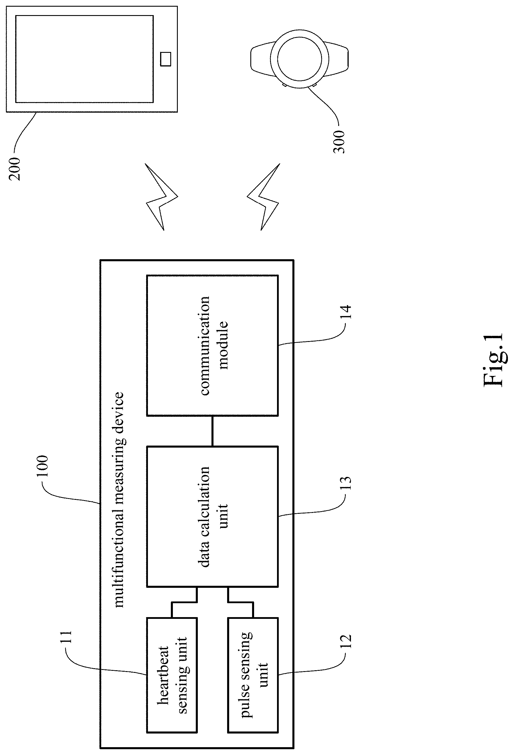
[0021] FIG. 1 is a first block diagram of the multifunctional measuring device of the present invention.
[0022] FIG. 2 is a second block diagram of the multifunctional measuring device of the present invention.
[0023] FIG. 3 shows a state of use of a multifunctional measuring device according to embodiment 1 of the present invention.
[0024] FIG. 4 is an oscillogram of a multifunctional measuring device according to embodiment 1 of the present invention.
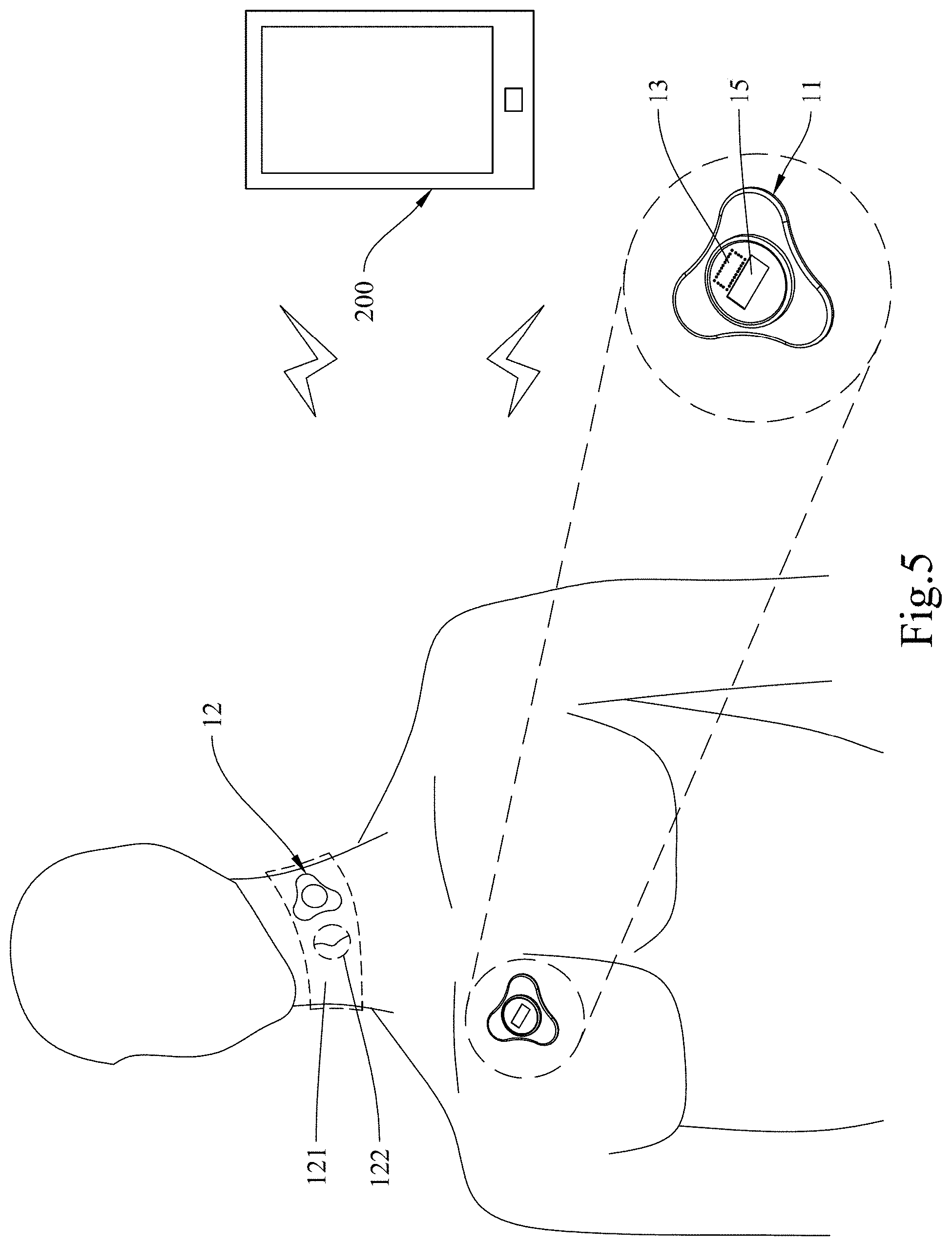
[0025] FIG. 5 shows a state of use of a multifunctional measuring device according to embodiment 2 of the present invention.
[0026] FIG. 6 is an audiogram for the heart sound in the aortic valve area about a multifunctional measuring device of embodiment 2 of the present invention.
[0027] FIG. 7 is an oscillogram for the right carotid arteries about a multifunctional measuring device of embodiment 2 of the present invention.
[0028] FIG. 8 shows the oscillogram images of embodiment 1 of the present invention and comparative example 1.
[0029] FIG. 9 is the correlation analysis result of embodiment 1 of the present invention and comparative example 1.
[0030] FIG. 10 is the first correlation analysis result of embodiment 1 of the present invention and comparative example 2.
[0031] FIG. 11 is the second correlation analysis result of embodiment 1 of the present invention and comparative example 2.
[0032] FIG. 12 is the third correlation analysis result of embodiment 1 of the present invention and comparative example 2.
[0033] FIG. 13 shows the carotid waveforms according to validation and verification example 3 of the present invention.
DETAILED DESCRIPTION OF THE INVENTION
[0034] The details and technical solution of the present invention are hereunder described with reference to accompanying drawings. For illustrative sake, the accompanying drawings are not drawn to scale. The accompanying drawings and the scale thereof are not restrictive of the present invention.
[0035] The use of "comprise" means not excluding the presence or addition of one or more other components, steps, operations, or elements to the described components, steps, operations, or elements, respectively. Similarly, "comprise," "comprises," "comprising," "include," "includes," and "including" are interchangeable and not intended to be limiting. As used herein and in the appended claims, the singular forms "a," "an," and "the" include plural referents unless the context dictates otherwise. The terms "a", "an," "the," "one or more," and "at least one," for example, can be used interchangeably herein.
[0036] In the following, the present invention will be further described with detailed descriptions and embodiments. However, it should be understood that these embodiments are only used to help make the present invention easier to understand, rather than to limit the scope of the present invention.
[0037] Please refer to FIG. 1 and FIG. 2 respectively for two block diagrams of the multifunctional measuring device according to a preferred embodiment of the present invention.
[0038] The primary objective of the present invention is to provide a multifunctional measuring device 100 that is capable of determining carotid blood pressure. The multifunctional measuring device 100 includes a heartbeat sensing unit 11 to be disposed on a subject's chest to obtain heartbeat signals, a pulse sensing unit 12 to be disposed on the subject's neck at a position corresponding to the carotid arteries in order to obtain pulse signals, and a data calculation unit 13 in communication with the heartbeat sensing unit 11 and the pulse sensing unit 12 in order to process signals coming from the heartbeat sensing unit 11 and from the pulse sensing unit 12. In particular, the data calculation unit 13 calculates with the heartbeat signals coming from the heartbeat sensing unit 11 and the pulse signals coming from the pulse sensing unit 12 in order to obtain the mean arterial pressure (MAP) of the subject's carotid arteries.
[0039] The carotid arteries, which are responsible for supplying blood to the brain and the neck, can be divided into a left part and a right part, each part including a common carotid artery arising from the aorta and two branches (i.e., an external carotid artery and an internal carotid artery) from the common carotid artery. The external carotid artery is the major source of facial blood flow, while the internal carotid artery serves mainly to supply blood to brain tissues. The carotid arteries are shallow, easy to detect, and hence a desirable window through which to discover such diseases as arteriosclerosis.
[0040] As used herein, the term "heartbeat sensing unit 11" refers to an assembly of components configured to obtain heartbeat signals in real time. The heartbeat sensing unit 11 may include software as well as hardware and be further integrated with an auxiliary component. For example, the heartbeat sensing unit 11 may include a sensor for measuring heartbeat, a storage device for receiving and recording data, a data processor, and other related components; the present invention has no limitation in this regard. The "related components" may be, but are not limited to, a signal amplifier, a power supply device, a microcontroller, a communication unit, a power unit, and a display unit. The aforesaid software may be, but is not limited to, software for data collection or feature extraction, software for signal amplification, and software for data calculation and analysis. The auxiliary component may be, but is not limited to, an adhesive patch, an electronic adhesive patch, or an auxiliary component to render the heartbeat sensing unit 11 easy to grip. In one preferred embodiment, the heartbeat sensing unit 11 is an acoustic wave sensor; in other words, the acoustic wave sensor is used to obtain the sound/acoustic wave signals (also known as heart sound signals) generated by pulsation of the heart. Heart sound signals correspond to the operation of the cardiac valves and can therefore be converted into heartbeat signals. Now that heart sound signals reflect the operation of the cardiac valves, the heartbeat sensing unit 11 can, apart from communicating with and working in conjunction with the pulse sensing unit 12 and the data calculation unit 13, work alone to obtain the subject's heart sound signals, in order for the frequency and intensity of the heart sound and the relationship therebetween to reflect the conditions of the cardiac valves, of the cardiac muscle function, and of the blood flow in the heart, thereby facilitating the determination of the presence or absence of irregular heart sound or other cardiac abnormalities. As to the position where the heartbeat sensing unit 11 is to be disposed, the heartbeat sensing unit 11 in one preferred embodiment is configured to be disposed on a subject's chest at a position corresponding to the vicinity of a cardiac valve, such as the vicinity of an atrioventricular valve (e.g., the mitral valve or the tricuspid valve) or the vicinity of a semilunar valve (e.g., the aortic valve or the pulmonary valve, which are respectively in the two arteries leaving the heart, namely the aorta and the pulmonary artery).
[0041] As used herein, the term "pulse sensing unit 12" refers to an assembly of components configured to obtain pulse signals in real time. The pulse sensing unit 12 may include software as well as hardware and be further integrated with an auxiliary component. For example, the pulse sensing unit 12 may include a sensor for measuring the pulse, a storage device for receiving and recording data, a data processor, and other related components; the present invention has no limitation in this regard. The "related components" may be, but are not limited to, a signal amplifier, a power supply device, a microcontroller, a communication unit, a power unit, and a display unit. The aforesaid software may be, but is not limited to, software for data collection or feature extraction, software for signal amplification, and software for data calculation and analysis. The auxiliary component may be, but is not limited to, an adhesive patch, an electronic adhesive patch, or an auxiliary component to render the pulse sensing unit 12 easy to grip. In one preferred embodiment, the pulse sensing unit 12 is a pulse wave sensor capable of converting the pulse wave signals obtained into pulse signals. The pulse sensing unit 12 may be, but is not limited to, a Doppler radar, a piezoelectric sensor, a piezoresistive pressure sensor, a capacitive pressure sensor, an acoustic wave sensor, an ultrasound sensor, a photoplethysmographic (PPG) sensor, or other sensors capable of sensing pulse wave signals. In addition to communicating with and working in conjunction with the heartbeat sensing unit 11 and the data calculation unit 13, the pulse sensing unit 12 can work alone to obtain a subject's pulse wave signals for example, thereby facilitating the determination of the presence or absence of an irregular pulse or arrhythmia. As to the position where the pulse sensing unit 12 is to be disposed, the pulse sensing unit 12 in one preferred embodiment is configured to be disposed on a subject's neck at a position corresponding to the carotid arteries, wherein the position may correspond to the left or the right carotid arteries. In a more preferred embodiment, the pulse sensing unit 12 is configured to be disposed at a pulse measuring point on the neck. Optimally, the pulse measuring point is a point in a line segment defined as follows. The line segment starts from a starting point (or 0 cm position) defined as a point that is to the left or right of, and horizontally spaced apart by 3.+-.0.3 cm from, the peak of the thyroid cartilage (i.e., the laryngeal prominence) (or the most prominent point of the neck that lies right below the middle point of the lips), wherein the horizontal distance of 3.+-.0.3 cm may be, but is not limited to, 2.7 cm, 2.8 cm, 2.9 cm, 3 cm, 3.1 cm, 0.2 cm, or 3.3 cm. The line segment extends from the starting point (or 0 cm position) for 4 cm along a direction that extends distally at an angle of 135 degrees with respect to the horizontal direction. For example, the pulse measuring point may be 1 cm, 2 cm, 3 cm, or up to 4 cm away from the starting point (or 0 cm position) in the direction extending distally at the angle of 135 degrees with respect to the horizontal direction. The pulse measuring point of the invention, however, is not limited to a point in the aforesaid line segment; the line segment defined above is only an exemplary range that allows pulse signals to be effectively obtained. Furthermore, to make it easier to dispose the pulse sensing unit 12 on a subject's neck at a position corresponding to the subject's carotid arteries (i.e., at the carotid pulse measuring point), the pulse sensing unit 12 in one preferred embodiment includes an adhesive patch with a thyroid cartilage locating portion. The thyroid cartilage locating portion may be, but is not limited to, a locating hole, a locating mark, or other similar features with a thyroid cartilage locating function; the invention has no limitation on the locating means to be used. Moreover, the pulse sensing unit 12 of the invention may have other functions than obtaining the pulse waves and pulse signals of the carotid arteries, depending on the type of the pulse sensor employed. For example, the pulse sensing unit 12 will be able to obtain the blood flow sound in the neck if an acoustic wave sensor is used, and the blood flow/pulse wave velocity in the neck if a Doppler radar is used. The foregoing configuration is advantageous in that the pulse sensing unit 12 can not only monitor the carotid pulse, but also measure variation in the carotid blood flow in real time.
[0042] As used herein, the term "data calculation unit 13" refers to an assembly of components configured for signal processing and computation. The data calculation unit 13 may include software as well as hardware and be further integrated with an auxiliary component. For example, the data calculation unit 13 may include a storage device for receiving and recording data, a data processor, and other related components; the present invention has no limitation in this regard. The "related components" may be, but are not limited to, a signal amplifier, a power supply device, a microcontroller, a communication unit, a power unit, and a display unit. The aforesaid software may be, but is not limited to, software for data collection or feature extraction, software for signal amplification, and software for data calculation and analysis. The data calculation unit 13 is connected or coupled to, and is configured to communicate with, the heartbeat sensing unit 11 and the pulse sensing unit 12. The data calculation unit 13 is configured to process the signals and/or other data and parameters obtained by the heartbeat sensing unit 11 and the pulse sensing unit 12 in order to calculate various parameters. As an upstream device of the sensors (i.e., the heartbeat sensing unit 11 and the pulse sensing unit 12), the data calculation unit 13 may be provided with an amplitude filter 131 and an analog-to-digital converter 132 as shown in FIG. 2, in order to carry out signal preprocessing, e.g., to convert the signals of the sensors into digital ones to facilitate computation. In one preferred embodiment, the data calculation unit 13 is configured to communicate with the heartbeat sensing unit 11 and the pulse sensing unit 12, to process signals coming from the heartbeat sensing unit 11 and the pulse sensing unit 12, to calculate the mean arterial pressure (MAP) using the time differences between heartbeats and between the corresponding pulses, and to derive the subject's systolic pressure and diastolic pressure from the mean arterial pressure. As to the position of the data calculation unit 13, the data calculation unit 13 in one preferred embodiment is provided in the heartbeat sensing unit 11, the pulse sensing unit 12, or a portable device. In another preferred embodiment, the data calculation unit 13 is provided in the heartbeat sensing unit 11 or the pulse sensing unit 12 and a portable device. In one preferred embodiment, the data calculation unit 13 is further connected to a communication module 14, and the communication module 14 is configured to pair with a portable device, access the data obtained by the data calculation unit 13, and by means of the configuration of the portable device, output the computation result of the data calculation unit 13 to the portable device.
[0043] As used herein, the term "communication" refers to wired or wireless transmission-based communication. For example, the heartbeat sensing unit 11, the pulse sensing unit 12, and the data calculation unit 13 may be connected by wires or coupled to one another through wireless communication modules in order to communicate with one another. The wireless communication modules may be, but are not limited to, Bluetooth communication modules, WIFI communication modules, radio frequency identification (RFID) communication modules, near-field communication (NFC) modules, Zigbee communication modules, wireless local area network (WLAN) communication modules, or the like; the present invention has no limitation in this regard.
[0044] As used herein, the term "portable device" refers to an electronic device that can be easily carried around, such as a handheld device 200, a wearable device 300, a smart mobile device, or the like. In one preferred embodiment, the multifunctional measuring device 100 of the present invention is configured for use with the handheld device 200 or the wearable device 300, in order for the handheld device 200 or the wearable device 300 to access and process the data measured and obtained by the multifunctional measuring device 100.
[0045] The multifunctional measuring device 100 of the present invention can be used to obtain a variety of physiological data, such as carotid blood pressure, heart sound, blood flow sound, pulse wave velocity, and the degree of carotid stenosis.
[0046] The "blood pressure" and the "pulse wave velocity" can be obtained by the method described below.
[0047] The heart pumps blood into the aorta in a pulsing manner. The wall of the aorta, therefore, generates pulse pressure waves, which propagate to the downstream blood vessels at a certain velocity along the blood vessel walls. The velocity at which such pulse pressure waves propagate along the artery walls is referred to as the pulse wave velocity (PWV).
[0048] The PWV is related to such factors as the biophysical properties of the artery walls, the geometric properties of the blood vessels involved, and the density of blood. The value of the PWV is an early sensitive indicator of the stiffness (or narrowness) of the arteries. The larger the value, the stiffer the blood vessel walls (or the narrower the blood vessels). The standard/normal PWV is 140 mm/ms.
[0049] The PWV of a carotid artery can be calculated from the pulse wave propagation time and distance between two artery recording positions (e.g., the position where a common carotid artery originates from the aorta and a predetermined position of the common carotid artery), the equation for the calculation being:
PWV = L t ( mm / ms ) , ##EQU00002##
where t is the time difference between two adjacent waveforms, i.e., the propagation time, and L is the distance between the two artery sensors, i.e., the propagation distance (e.g., the distance between the aortic valve and the pulse measuring point).
[0050] An increase in the PWV of a carotid artery implies an increase in the stiffness (or narrowness) of the carotid artery and a decrease in the compliance of the carotid artery. Conversely, a carotid artery with a low PWV has low stiffness and high compliance. Age and blood pressure are the main factors that influence the PWV, and antihypertensive therapy currently remains the most effective method for reducing the PWV.
[0051] Calculation of the carotid PWV is based on the relationship between pressure and the PWV. In each cardiac cycle, the contraction of the left ventricle generates a pressure pulse that propagates through the arteries to the very ends of those blood vessels. The PWV of an artery is a function of the stiffness of the artery, as can be expressed by equation (a):
PWV = ( V .rho. ) ( d P d V ) , equation ( a ) ##EQU00003##
[0052] where .rho. is the density of blood.
[0053] The stiffness of a carotid artery is associated with the transmural pressure across the artery wall, and this pressure is a function of the geometry of the blood vessel and the viscoelasticity of the blood vessel wall. As the pressure acting on an artery wall from outside the artery is typically negligible, the stiffness and PWV of a carotid artery are a function of the artery, and the pulses in propagation form the basis of carotid stenosis measurement.
[0054] More specifically, correlation between the PWV and arterial pressure forms the basis of non-invasive blood pressure measurement. In particular, the PWV has the strongest correlation to diastolic pressure and mean arterial pressure, as can be expressed by equation (b):
PWV=fcn (MAP ) equation (b).
[0055] The relationship between the PWV and mean arterial pressure can be accurately described by the following linear model equation (c):
PWV (t )=.alpha.MAP (t )+pwv.sub.0 equation (c),
[0056] where the slope .alpha. and the constant pwv.sub.0 are subject-specific parameters.
[0057] To trace a patient's pulse pressure and velocity, the present invention uses the heartbeat sensing unit 11 and the pulse sensing unit 12 to monitor a known parameter, i.e., the pulse arrival time (PAT). Each pulse arrival time measurement is in fact the sum of two different periods of time, namely the vascular transit time (VTT) and the pre-ejection period (PEP). The vascular transit time is the time for which a pressure pulse travels along an arterial path. The pre-ejection period is the time interval between two adjacent peaks of a composite wave, or the interval at which the aortic valve opens, and includes electromechanical delay and isovolumic contraction. The pulse arrival time can be expressed by equation (d):
P A T = V T T + P E P = ( L t P W V ) + PEP , equation ( d ) ##EQU00004##
[0058] where the parameter L.sub.t is the length of the path along which a pressure pulse propagates in an artery.
[0059] Assuming the pre-ejection period is constant while monitoring takes place, a change in the vascular transit time directly results in a change in the pulse arrival time, and these two parameters are associated with variation of the mean arterial pressure. To establish the relationship between pulse arrival time and mean arterial pressure and the linear relationship between mean arterial pressure and PWV, it behaves as if equation (b) must be abstracted and defined in measuring the pulse delay time at the individual measurement pulse arrival time, as expressed by equation (e):
P A T = ( L t P W V ) = ( L t a M A P + p w .nu. 0 ) . equation ( e ) ##EQU00005##
[0060] In one preferred embodiment, mean arterial pressure is obtained through the following equation (I):
mean arterial pressure ( MAP ) = a ( l p t p a .times. c ) + b , equation ( I ) ##EQU00006##
[0061] where l.sub.p is the length of the path along which the pulse propagates through the arteries between the aortic valve and the pulse measuring point; t.sub.pa is the times it takes for a pulse to reach the pulse measuring point from the aortic valve; and a, b, and c are correction parameters. The correction parameters are derived from a target subject database to provide necessary adjustment to the calculation.
[0062] In another preferred embodiment, mean arterial pressure is obtained through the following equation (II):
mean arterial pressure ( MAP ) = A ( l p t p a .times. C ) 2 + B , equation ( II ) ##EQU00007##
[0063] where l.sub.p is the length of the path along which the pulse propagates through the arteries between the aortic valve and the pulse measuring point; t.sub.pa is the times it takes for a pulse to reach the pulse measuring point from the aortic valve; and A, B, and C are correction parameters. The correction parameters are derived from a target subject database to provide necessary adjustment to the calculation.
[0064] Mean arterial pressure can be derived from the time difference between the pulse response at the position where the heartbeat sensing unit 11 is disposed on a subject's chest (hereinafter also referred to as the chest position) and the pulse response at the position where the pulse sensing unit 12 is disposed on the subject's neck (hereinafter also referred to as the neck position). In one preferred embodiment, the pulse arrival time is obtained by measuring the time difference between a peak value detected by the heartbeat sensing unit 11 and the corresponding peak value detected by the pulse sensing unit 12. In another preferred embodiment, the pulse arrival time is obtained by measuring the time difference between a signal valley detected by the heartbeat sensing unit 11 and the corresponding signal valley detected by the pulse sensing unit 12, wherein the measurement is triggered by the signal valleys. The present invention has no limitation on the method by which to determine the pulse arrival time.
[0065] Through the foregoing calculation, the pulse wave velocity in a target arterial section (i.e., the section between the chest position and the neck position) can be obtained, and mean arterial pressure (MAP) can be derived from the pulse wave velocity obtained. The severity of atherosclerosis in the target arterial section can then be assessed by analyzing the mean arterial pressure. The aforesaid data can also be provided to caregivers as a way to achieve real-time monitoring.
[0066] Apart from the data calculation unit 13 of the multifunctional measuring device 100, the afore-mentioned calculation may be performed by a program installed in the handheld device 200 or the wearable device 300 and be controlled by a controller in the handheld device 200 or the wearable device 300 instead, in order to reduce the power required by the multifunctional measuring device 100, allow the data calculation unit 13 of the multifunctional measuring device 100 to be miniaturized, and decrease the weight of the multifunctional measuring device 100.
[0067] "Heart sound" refers to the various sound generated by the heart while it is working and can be obtained by the method described below. The sound produced by the opening and closing of cardiac valves in a cardiac cycle has been frequently used in the medical field. For example, the first heart sound (S1) at the beginning of a systole is often produced by the mitral valve and the tricuspid valve, and the second heart sound (S2) at the beginning of a diastole, by the closing of the aortic valve. Heart sound signals, therefore, can be converted into heartbeat signals to shed light on the cardiac cycle. In one preferred embodiment, the heartbeat sensing unit 11 is an acoustic wave sensor to be disposed at the chest position, which corresponds to the vicinity of the aortic valve, the pulmonary valve, the tricuspid valve, or the mitral valve, and by disposing the heartbeat sensing unit 11 adjacent to a cardiac valve, the heartbeat sensing unit 11 can be used to obtain noise/irregular sound from that cardiac valve area. The information obtained can help diagnose valvular heart disease such as mitral stenosis or insufficiency, tricuspid stenosis or insufficiency, aortic stenosis or insufficiency, and pulmonary stenosis or insufficiency.
[0068] "Carotid stenosis" can be detected by the method described below.
[0069] As stated above, the carotid arteries on either side of the human body can be divided into three major portions: the common carotid artery, the external carotid artery, and the internal carotid artery. The facial blood flow involves intercommunication (also referred to as anatomical anastomosis) between the external and the internal carotid arteries; that is to say, a portion of the facial blood flow may pass through the internal carotid artery via the aforesaid intercommunication. For example, the external carotid artery may communicate with the internal carotid artery through the internal maxillary artery or with the ophthalmic artery through the facial artery. While the facial blood flow comes mainly from the external carotid artery, the external carotid artery is also closely related to the internal carotid artery, which supplies blood directly to brain tissues and therefore may contribute to the occurrence of strokes, in three ways. First, most of the atheromatous plaque in the carotid arteries is distributed over the junction between the external and the internal carotid arteries; therefore, stenosis of the external carotid artery tends to have a sustained effect on the atheromatous plaque in the adjacent internal carotid artery or even affect the blood flow in the common carotid artery. Second, given the anatomical anastomosis between the internal carotid artery and the external carotid artery, stenosis of the internal carotid artery may result in the so-called steal phenomenon and hence reduce the blood flow in the same side of the face. Third, as the external carotid artery accounts for 12 % of the cerebral blood flow, a reduced blood flow in the neck caused by stenosis of the external carotid artery is associated also with insufficient cerebral blood flow on the same side, and it is anticipated that a reduced blood flow caused by stenosis of the external carotid artery may have something to do with stenosis of the internal carotid artery on the same side, too. Based on the foregoing, the multifunctional measuring device 100 of the present invention detects carotid stenosis by obtaining information about the blood flow pulse waves in the neck. Conventionally, the peak systolic velocity (PSV) of the carotid arteries is used to determine the degree of carotid stenosis, and the PSV-based classification of carotid stenosis is shown in TABLE 1.
TABLE-US-00001 TABLE 1 Minor Moderate Serious Severe Critical stenosis stenosis stenosis stenosis stenosis Classification (0-29%) (30%-49%) (50%-69%) (70%-99%) (100%) PSV <120 120-149 150-249 >250 Zero (cm/sec) velocity
[0070] To obtain the pulse wave velocity and other parameters of the carotid arteries, the neck position, where the pulse sensing unit 12 is disposed, corresponds to the carotid arteries. In one preferred embodiment, the pulse sensing unit 12 is configured to be disposed at a pulse measuring point on the neck, or more particularly a pulse measuring point for the carotid arteries. Optimally, the pulse measuring point is a point in a line segment defined as follows. The line segment starts from a starting point (or 0 cm position) defined as a point that is to the left or right of, and horizontally spaced apart by 3.+-.0.3 cm from, the laryngeal prominence (or the most prominent point of the neck that lies right below the middle point of the lips), wherein the horizontal distance of 3.+-.0.3 cm may be, but is not limited to, 2.7 cm, 2.8 cm, 2.9 cm, 3 cm, 3.1 cm, 3.2 cm, or 3.3 cm. The line segment extends from the starting point (or 0 cm position) for 4 cm along a direction that extends distally at an angle of 135 degrees with respect to the horizontal direction. For example, the pulse measuring point may be 1 cm, 2 cm, 3 cm, or up to 4 cm away from the starting point (or 0 cm position) in the direction extending distally at the angle of 135 degrees with respect to the horizontal direction. The pulse measuring point of the present invention, however, is not limited to a point in the aforesaid line segment; the line segment defined above is only an exemplary range that allows pulse signals to be effectively obtained. In a more preferred embodiment, the optimal pulse measuring point of a male subject is determined as follows. The first step is to find a starting point that is to the left or right of, and horizontally spaced apart by 3.+-.0.3 cm from, the laryngeal prominence (or the most prominent point of the neck that lies right below the middle point of the lips). The second step is to locate the optimal pulse measuring point by finding the point that is 3 cm away from the starting point in a direction that extends distally at an angle of 135 degrees with respect to the horizontal direction. Similarly, the optimal pulse measuring point of a female subject is determined by first finding a starting point that is to the left or right of, and horizontally spaced apart by 3 cm from, the laryngeal prominence (or the most prominent point of the neck that lies right below the middle point of the lips), and then finding the point that is 3 cm away from the starting point in a direction that extends distally at an angle of 135 degrees with respect to the horizontal direction as the optimal pulse measuring point. In one preferred embodiment, the neck position, where the pulse sensing unit 12 is disposed, may be any position corresponding to the left carotid arteries or the right carotid arteries. In one preferred embodiment, the pulse sensing unit 12 is configured to be disposed at a position corresponding to a disease-affected or high-risk portion of the subject's body, such as but not limited to a position on the subject's neck that corresponds to the left or right common carotid artery or to the outlet of the left or right common carotid artery (i.e., the junction between the corresponding external carotid artery and internal carotid artery, also known as a carotid bifurcation). As the external carotid artery and the internal carotid artery are the two branches of the common carotid artery, the flow velocity in the common carotid artery can be directly used to assess the possibility of atherosclerosis of the external carotid artery and the internal carotid artery. If it is desired to assess the condition of the external carotid artery or the internal carotid artery alone, the position of the pulse sensing unit 12 can be adjusted as needed. In addition to the pulse sensing unit 12, the invention may include more sensors in order to sense the blood flow sound waves, pulse wave velocities, pulse waveforms, or other necessary physiological parameters in different sections of the carotid arteries respectively, thereby obtaining a relatively complete set of assessment data of the common and branch carotid arteries.
I. Embodiment 1
[0071] Please refer to FIG. 3 and FIG. 4 respectively for a state of use and an oscillogram of a multifunctional measuring device according to the present invention.
[0072] As shown in FIG. 3, the multifunctional measuring device 100 includes a heartbeat sensing unit 11, a pulse sensing unit 12, and a data calculation unit 13. The data calculation unit 13 is implemented as a program installed in a handheld device 200. The heartbeat sensing unit 11, the pulse sensing unit 12, and the data calculation unit 13 are configured to communicate with one another wirelessly via Bluetooth.
[0073] The heartbeat sensing unit 11 includes an acoustic wave sensor and an adhesive patch by which the heartbeat sensing unit 11 can be adhesively attached to a subject's chest at a position corresponding to the aortic valve in order to obtain heart sound, heartbeat signals, etc.
[0074] The pulse sensing unit 12 includes a pressure sensor and an adhesive patch 121 by which the pulse sensing unit 12 can be adhesively attached to a subject's neck at a position corresponding to the outlet of the right common carotid artery in order to obtain carotid pulse waveforms, pulse signals, etc.
[0075] FIG. 4 shows an example of the waveforms obtained, in which the lower waveform represents the blood flow sound waves at the aortic valve and the upper waveform represents the blood flow pulse waves of the right common carotid artery. The dashed line-enclosed portions are a first-heart-sound peak (indicating the start of a systole) obtained by the heartbeat sensing unit 11 and the corresponding peak obtained by the pulse sensing unit 12. The time difference between the aforesaid two peaks in a cardiac cycle is the pulse arrival time (T.sub.PA ), and the distance between the aortic valve and the pulse measuring point can be viewed as the length (L.sub.p ) of the path along which the pulse propagates through the arteries. The data calculation unit 13 can calculate the carotid blood pressure, pulse wave velocity, etc. according to T.sub.PA and L.sub.p.
II. Embodiment 2
[0076] Please refer to FIG. 5, FIG. 6, and FIG. 7 respectively for a state of use of a multifunctional measuring device according to the present invention, an audiogram for the heart sound in the aortic valve area, and an oscillogram for the right carotid arteries.
[0077] As shown in FIG. 5, the multifunctional measuring device 100 includes a heartbeat sensing unit 11, a pulse sensing unit 12, and a data calculation unit 13. The data calculation unit 13 is installed in the heartbeat sensing unit 11 and is connected to the heartbeat sensing unit 11 by wires. The heartbeat sensing unit 11 and the data calculation unit 13 are configured to communicate with the pulse sensing unit 12 wirelessly via Bluetooth.
[0078] The heartbeat sensing unit 11 includes an acoustic wave sensor, a display unit 15, and an adhesive patch by which the heartbeat sensing unit 11 can be adhesively attached to a subject's chest at a position corresponding to the aortic valve in order to obtain heart sound, heartbeat signals, etc. The display unit 15 is configured to display such contents as the heart sound waveforms and the calculation result of the data calculation unit 13. FIG. 6 shows an example of the waveforms obtained by the heartbeat sensing unit 11.
[0079] The pulse sensing unit 12 includes an acoustic wave sensor and an adhesive patch 121 with a thyroid cartilage locating portion 122. The thyroid cartilage locating portion 122 is a hole so that by aligning the thyroid cartilage locating portion 122 of the adhesive patch 121 with a subject's thyroid cartilage, the pulse sensing unit 12 can be easily attached to the subject's neck at a position corresponding to the left or right common carotid artery in order to obtain carotid pulse waveforms, pulse signals, etc. FIG. 7 shows an example of the waveforms obtained from the right carotid arteries. One advantage of using an acoustic wave sensor as the detector of the pulse sensing unit 12 is that, in addition to pulse-related data, the pulse sensing unit 12 can obtain the carotid blood flow sound to facilitate clinical diagnosis of abnormalities (e.g., noise or irregular sound) of the carotid blood flow.
[0080] The data calculation unit 13 can calculate the carotid blood pressure, pulse wave velocity, etc. according to the pulse arrival time (T.sub.PA ), which is the time difference between a first-heart-sound peak (indicating the start of a systole) obtained by the heartbeat sensing unit 11 and the corresponding peak obtained by the pulse sensing unit 12 in a cardiac cycle, and the distance between the aortic valve and the pulse measuring point, which distance can be viewed as the length (L.sub.p) of the path along which the pulse propagates through the arteries.
COMPARATIVE EXAMPLES 1 and 2
[0081] Comparative example 1 is a Mindray color Doppler ultrasound diagnosis system, which uses a conventional clinical detection technique. The right carotid arteries are manually detected in real time, and the detection data are recorded.
[0082] Comparative example 2 is a commercially available sphygmomanometer for use as an artery stenosis detector/pulse wave recorder to record the blood flow sound waves in the carotid arteries.
VALIDATION AND VERIFICATION EXAMPLE 1
[0083] Please refer to FIG. 8 and FIG. 9 respectively for the oscillogram images and correlation analysis result of embodiment 1 and comparative example 1.
[0084] The present invention was compared with a similar product (i.e., the conventional ultrasound diagnosis system of comparative example 1 ) for validation and verification. In this validation and verification example, a group of 25 subjects (including healthy people and those who might have carotid stenosis) were examined using comparative example 1 as well as embodiment 1. The screen images of the two sensing devices (see FIG. 8) were analyzed to determine the correlation between the pulse wave velocities obtained by embodiment 1 and the peak systolic velocities recorded by comparative example 1.
[0085] During the 30 seconds when measurements (or more particularly, 25 measurements of the aortic pulse wave velocity between the aortic valve and a predetermined position of the carotid arteries) were taken simultaneously with embodiment 1 and comparative example 1, there was a significant correlation, or a linear relationship (see FIG. 9), between the pulse wave velocities obtained by embodiment 1 and the peak systolic velocities obtained by comparative example 1, the correlation coefficient R being 0.897.
[0086] Therefore, the carotid pulse wave velocities obtained through the present invention can be used to determine the degree of carotid stenosis, as shown in TABLE 2.
TABLE-US-00002 TABLE 2 Minor Moderate Serious Severe Critical stenosis stenosis stenosis stenosis stenosis Classification (0-29%) (30%-49%) (50%-69%) (70%-99%) (100%) Pulse wave <120 120-149 150-249 >250 Zero velocity velocity (cm/sec)
VALIDATION AND VERIFICATION EXAMPLE 2
[0087] Please refer to FIG. 10, FIG. 11, and FIG. 12 for the correlation analysis results of embodiment 1 and comparative example 2.
[0088] Three subject groups of different sizes were examined using a commercially available sphygmomanometer (i.e., comparative example 2 ) as well as embodiment 1. The carotid pulse waves recorded by embodiment 1 and the carotid blood flow sound waves recorded by comparative example 2 were analyzed, and a correlation analysis was performed on the pulse wave velocities obtained by the two devices.
[0089] As shown in FIG. 10, which presents the correlation analysis result for the group consisting of five subjects, there was a significant correlation, or a linear relationship, between the pulse wave velocities obtained by embodiment 1 and those obtained by comparative example 2 during the 30 seconds when measurements were taken simultaneously with embodiment 1 and comparative example 2, the correlation coefficient R being 0.967.
[0090] As shown in FIG. 11, which presents the correlation analysis result for the group consisting of ten subjects, there was a significant correlation, or a linear relationship, between the pulse wave velocities obtained by embodiment 1 and those obtained by comparative example 2 during the 30 seconds when measurements were taken simultaneously with embodiment 1 and comparative example 2, the correlation coefficient R being 0.968.
[0091] As shown in FIG. 12, which presents the correlation analysis result for the group consisting of eleven subjects, there was a significant correlation, or a linear relationship, between the pulse wave velocities obtained by embodiment 1 and those obtained by comparative example 2 during the 30 seconds when measurements were taken simultaneously with embodiment 1 and comparative example 2, the correlation coefficient R being 0.950.
[0092] According to the above comparison results, the carotid pulse wave velocities obtained through the present invention had a significant correlation to those obtained by the commercially available sphygmomanometer. It follows that measurements taken with the present invention can be used to determine the degree of carotid stenosis and calculate carotid blood pressure.
VALIDATION AND VERIFICATION EXAMPLE 3
[0093] Please refer to FIG. 13 for the carotid waveforms obtained by disposing the pulse sensing unit 12 of the present invention at different pulse measuring points.
[0094] In this validation and verification example, male and female subjects were examined with embodiment 1, and the pulse measuring point where the pulse sensing unit 12 was disposed was varied between measurements. The various pulse measuring points to which the pulse sensing unit 12 was adhesively attached included: point A.sub.-0.3, which was to the right of, and horizontally spaced apart by 2.7 cm from, a subject's laryngeal prominence; point B.sub.0, which was to the right of, and horizontally spaced apart by 3 cm from, a subject's laryngeal prominence; point A.sub.+0.3, which was to the right of, and horizontally spaced apart by 3.3 cm from, a subject's laryngeal prominence; point B.sub.1, which was 1 cm away from point B.sub.0 (or the starting point, or 0 cm position) in a direction extending distally at an angle of 135 degrees with respect to the horizontal direction; point B.sub.2, which was 2 cm away from point B.sub.0 in the direction extending distally at the angle of 135 degrees with respect to the horizontal direction; point B.sub.3, which was 3 cm away from point B.sub.0 in the direction extending distally at the angle of 135 degrees with respect to the horizontal direction; point B.sub.4, which was 4 cm away from point B.sub.0 in the direction extending distally at the angle of 135 degrees with respect to the horizontal direction; and point B.sub.5, which was 5 cm away from point B.sub.0 in the direction extending distally at the angle of 135 degrees with respect to the horizontal direction.
[0095] According to the examination results, well-defined carotid pulse wave signals were obtained from point A.sub.-0.3, point B.sub.0, and point A.sub.+0.3 of the male subjects. While carotid pulse wave signals were also successfully obtained from point A.sub.-0.3, point B.sub.0, and point A.sub.+0.3 of the female subjects, the signals from point A.sub.-0.3 and point A.sub.+0.3 were relatively weak; only the signals from point B.sub.0 were relatively well-defined.
[0096] Moreover, regardless of the gender of the subjects, carotid pulse wave signals were successfully obtained from point B.sub.0 (see the lower waveform in FIG. 13), point B.sub.1, point B.sub.2, point B.sub.3 (see the upper waveform in FIG. 13), and point B.sub.4, with point B.sub.3 producing relatively well-defined signals and point B.sub.4 producing relatively weak signals. Pulse wave signals were hardly obtained from point B.sub.5. The obtainment of carotid pulse wave signals from point B.sub.4 and point B.sub.5 may have been hindered by the neighboring cartilage structure.
[0097] As above, the present invention provides a multifunctional measuring device that features non-invasive detection. More specifically, an acoustic wave sensor is adhesively attached via an adhesive patch to a subject's body at a position adjacent to one of the subject's cardiac valves, and a sensing unit selected as needed from a variety of options is adhesively attached to the subject's neck at a position adjacent to the carotid arteries. Not only can the multifunctional measuring device detect carotid blood pressure and pulse wave velocity, but also the measurement result can be used to diagnose carotid stenosis and determine the cerebral blood volume. The multifunctional measuring device of the invention is compact in size, can be held by hand, is portable, can measure the degree of carotid stenosis rapidly, and is suitable for use at home as well as in hospitals (e.g., by a physician for diagnosis purposes), nursing homes, research centers, and so on. The multifunctional measuring device of the invention is expected to have a strong demand in the global medical device market by those who are of an advanced age, who have had a stroke, or who have a high risk of cardiovascular disease.
[0098] The above is the detailed description of the present invention. However, the above is merely the preferred embodiment of the present invention and cannot be the limitation to the implement scope of the present invention, which means the variation and modification according to the present invention may still fall into the scope of the invention.
* * * * *
D00000
D00001
D00002
D00003
D00004
D00005
D00006
D00007
D00008
D00009
D00010
D00011


XML
uspto.report is an independent third-party trademark research tool that is not affiliated, endorsed, or sponsored by the United States Patent and Trademark Office (USPTO) or any other governmental organization. The information provided by uspto.report is based on publicly available data at the time of writing and is intended for informational purposes only.
While we strive to provide accurate and up-to-date information, we do not guarantee the accuracy, completeness, reliability, or suitability of the information displayed on this site. The use of this site is at your own risk. Any reliance you place on such information is therefore strictly at your own risk.
All official trademark data, including owner information, should be verified by visiting the official USPTO website at www.uspto.gov. This site is not intended to replace professional legal advice and should not be used as a substitute for consulting with a legal professional who is knowledgeable about trademark law.