A Tilted Roller System for Laminated Products
Caridis; Andrew Anthony ; et al.
U.S. patent application number 16/618315 was filed with the patent office on 2021-01-28 for a tilted roller system for laminated products. The applicant listed for this patent is Heat and Control, Inc.. Invention is credited to Andrew Anthony Caridis, Miguel Angel Gomez Angulo, Sergio Gonzalez Granados, Mario Lorenzana Saucedo, Leopoldo Zarate Andrade.
| Application Number | 20210022349 16/618315 |
| Document ID | / |
| Family ID | 1000005149317 |
| Filed Date | 2021-01-28 |


| United States Patent Application | 20210022349 |
| Kind Code | A1 |
| Caridis; Andrew Anthony ; et al. | January 28, 2021 |
A Tilted Roller System for Laminated Products
Abstract
A tilted roller system for preparing laminated products having different figures, including three-dimensional rolled figures, wherein said roller system comprises a conveyor band, a start roller band, a roller band and an unloading band.
| Inventors: | Caridis; Andrew Anthony; (San Carlos, CA) ; Zarate Andrade; Leopoldo; (Tlajomulco de Zuniga, MX) ; Gomez Angulo; Miguel Angel; (Zapopan, MX) ; Gonzalez Granados; Sergio; (Tlaquepaque, MX) ; Lorenzana Saucedo; Mario; (Tlaquepaque, MX) | ||||||||||
| Applicant: |
|
||||||||||
|---|---|---|---|---|---|---|---|---|---|---|---|
| Family ID: | 1000005149317 | ||||||||||
| Appl. No.: | 16/618315 | ||||||||||
| Filed: | September 25, 2017 | ||||||||||
| PCT Filed: | September 25, 2017 | ||||||||||
| PCT NO: | PCT/IB2017/055809 | ||||||||||
| 371 Date: | November 29, 2019 |
| Current U.S. Class: | 1/1 |
| Current CPC Class: | A21C 3/02 20130101; A21C 3/06 20130101; A23P 20/20 20160801; A21C 9/08 20130101 |
| International Class: | A21C 3/02 20060101 A21C003/02; A23P 20/20 20060101 A23P020/20 |
Foreign Application Data
| Date | Code | Application Number |
|---|---|---|
| Jun 5, 2017 | MX | MX/A/2017/007047 |
Claims
1. A roller band system for laminated products comprising: a conveyor band, substantially horizontal, for receiving and transporting laminated products, a start roller band which receives the laminated products from the conveyor band and begins their rolling, the start roller band has an inclination, such that it is not perpendicular to the horizontal conveyor band, a roller band which receives the products which were started to be rolled, rolls them and coveys them, the roller band in an inclined plane which is under the horizontal conveyor band, an unloading band which receives the rolled products and unloads them, said unloading band presents at least four sections with different inclinations, a first section with a substantially horizontal inclination, a second section with an ascending inclination, a third section with a substantially horizontal inclination and a fourth section with a descending inclination.
2. The system according to claim 1, wherein the system additionally comprises: a main mobile support structure over which the substantially horizontal conveyor band is found, a second mobile support structure over which the start roller band is set, and a third mobile support structure over which the roller band is set, wherein the unloading band is set on the lower part of the main support structure.
3. The system according to claim 1, wherein the system additionally comprises a feeding band which receives, conveys and feeds laminated products to the conveyor band.
4. The system according to claim 3, wherein the feeding band presents an entrance end, an exit end, a plurality of tracking rolling pins, a tightening rolling pin and a driving rolling pin.
5. The system according to claim 4, wherein the tightening rolling pin and the driving rolling pin are found set in a first mobile support structure, while the tracking rolling pins are distributed between the first support structure and the main support structure.
6. The system according to claim 4, wherein said tightening rolling pin is vertically displaced in a groove set on a lateral wall of the first support structure.
7. The system according to claim 2, wherein the first mobile support structure presents a pivot near the entrance end of the feeding band, in such a way that the first mobile support structure presents a dumping movement with regard to the main support structure.
8. The system according to claim 1, wherein said conveyor band presents an exit end opposite to an entrance end, a plurality of tracking rolling pins, a tightening rolling pin and a driving rolling pin.
9. The system according to claim 8, wherein the tightening rolling pin is angularly displaced to tighten the conveyor band and wherein said displacement is undertaken by means of a first servo motor.
10. The system according to claim 1, wherein said start roller band undertakes the rolling of the products at a second speed and in a second direction, which comprises a driver rolling pin and at least two tracking pins, said start roller band presents an inclination from between approximately 95.degree. to approximately 120.degree..
11. The system according to claim 2, wherein the second mobile support structure is found supported on a longitudinal guiding rail set on the main support structure to longitudinally move the start roller band in regards to the conveyor band, in such a way that said start roller band approaches/moves away from the conveyor band.
12. The laminate product roller system according to claim 2, wherein the rolling band presents an entrance end, an exit end, a plurality of tracking rolling pins, a tightening r pin and a driver rolling pin, wherein the entrance end is found at a point which is higher than the exit end, similarly, said entrance end is found under the exit end of the conveyor band and nearby to the work surface of the start roller hand.
13. The laminate product roller system according to claim 12, wherein the third mobile support structure which is found mounted unto a vertical guiding rail, said vertical guiding rail is found mounted unto the second mobile support structure, in such a way that said roller band moves vertically in relation to the start rolling band wherein this movement is undertaken by means of a third servo motor.
14. The laminate product roller system according to claim 13, wherein the third mobile support structure is found connected to the second support structure, in such a way that the roller band has two movements, a vertical movement and a longitudinal movement.
15. The laminate product roller system according to claim 1, wherein said unloading band presents a third speed and moves in a third direction, which comprises an entrance end, an exit end, a plurality of tracking rolling pins, one tightening rolling pin and one driver rolling pin.
16. The laminate product roller system according to claim 1, wherein said substantially horizontal conveyor band is a parabolic convex band which conveys the products in a first direction at a first speed.
Description
OBJECT OF THE INVENTION
[0001] Present invention refers to a roller system for laminated products which present different figures from at least one type of mass and a combination of them, with the end goal of obtaining different tridimensional rolled figures, for the at least one of their later baking and frying.
BACKGROUND OF THE INVENTION
[0002] The rolling methods which exist in the industry only allow for the rolling of the laminated figure, without being able to achieve an open rolling or to control the degree of rolling of the laminated figure, so that the latter is always maintained closed and different figures with the same feeding direction and laminated shapes are not generated. These types of methods are very limited in the laminated shapes that can be developed, given that the rolling carried out by means of band sections placed vertically, and which rest over a horizontal band which is the one which feeds the laminated figures into the oven.
[0003] In a similar manner, application MX/a/2014/016071 divulges a rolling system for laminated products which comprises a horizontal conveyor band and a band for the start of the rolling, wherein said start rolling band is found in a perpendicular manner to the horizontal conveyor band.
[0004] Notwithstanding the rollers which are already known in the state of the art, the need still exists for rolling systems which allow for the carrying out of laminated products in different directions, mainly which will allow the controlling of the opening or closing of the rolling of the laminated product to be fed, as well as freeing the rolling at the desired point to achieve different rolled figures from the same laminated figure.
BRIEF DESCRIPTION OF THE INVENTION
[0005] Present invention refers to a rolling system for laminated products which comprises a conveyor hand which is substantially horizontal for receiving and transporting laminated products, a start: rolling band which receives the laminated products from the conveyor band and begins their rolling, the start roller band has an inclination, such that it is not perpendicular to the horizontal conveyor band, a roller band which receives the products which were started to be rolled, rolls them and coveys them, the roller band in an inclined plane which is under the horizontal conveyor band, an unloading band which receives the rolled products and unloads them, said unloading band presents at least four sections with different inclinations, a first section with a substantially horizontal inclination, a second section with an ascending inclination, a third section with a substantially horizontal inclination and a fourth section with a descending inclination.
BRIEF DESCRIPTION OF THE FIGURES
[0006] The illustrative embodiment may be described referencing the accompanying figures, which refer to:
[0007] FIG. 1 shows an isometric view of the roller system for laminated products of the present invention.
[0008] FIG. 2 shows a longitudinal cut of the roller system for laminated products of the present invention.
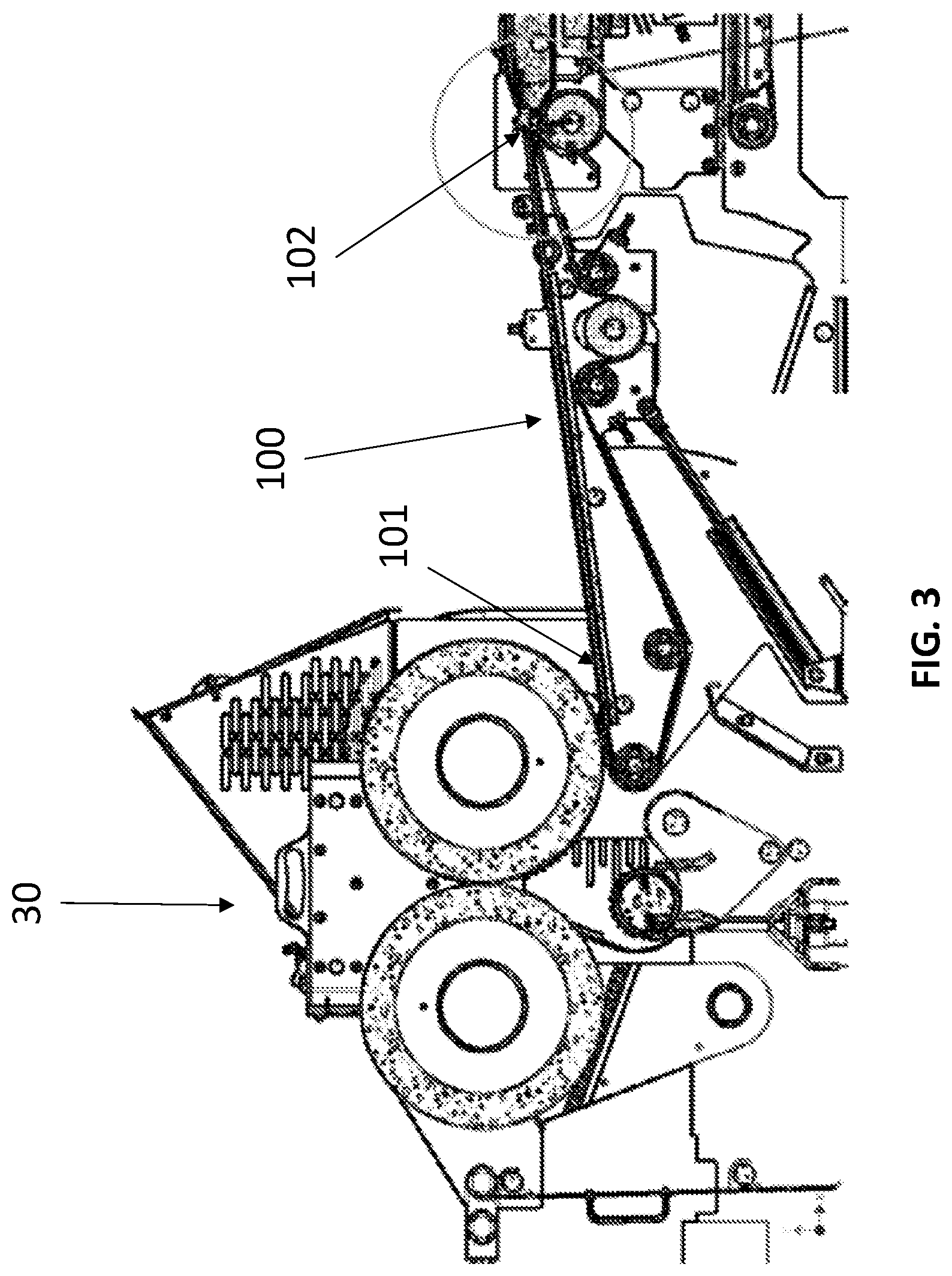
[0009] FIG. 3 shows the communication between the exit of the laminated product from the rolling pins to the feeding band in detail.
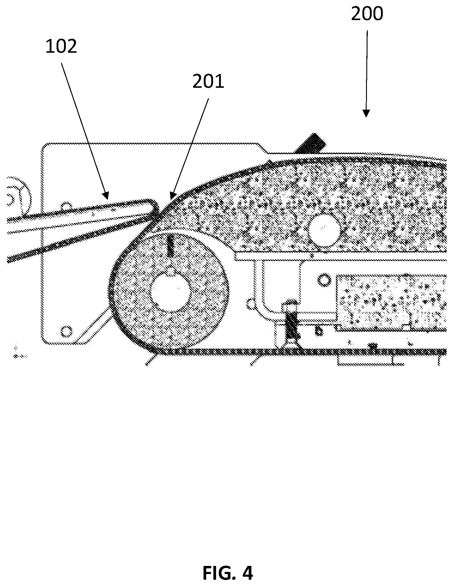
[0010] FIG. 4 shows the overlap between the feeding band and the conveyor band in detail.
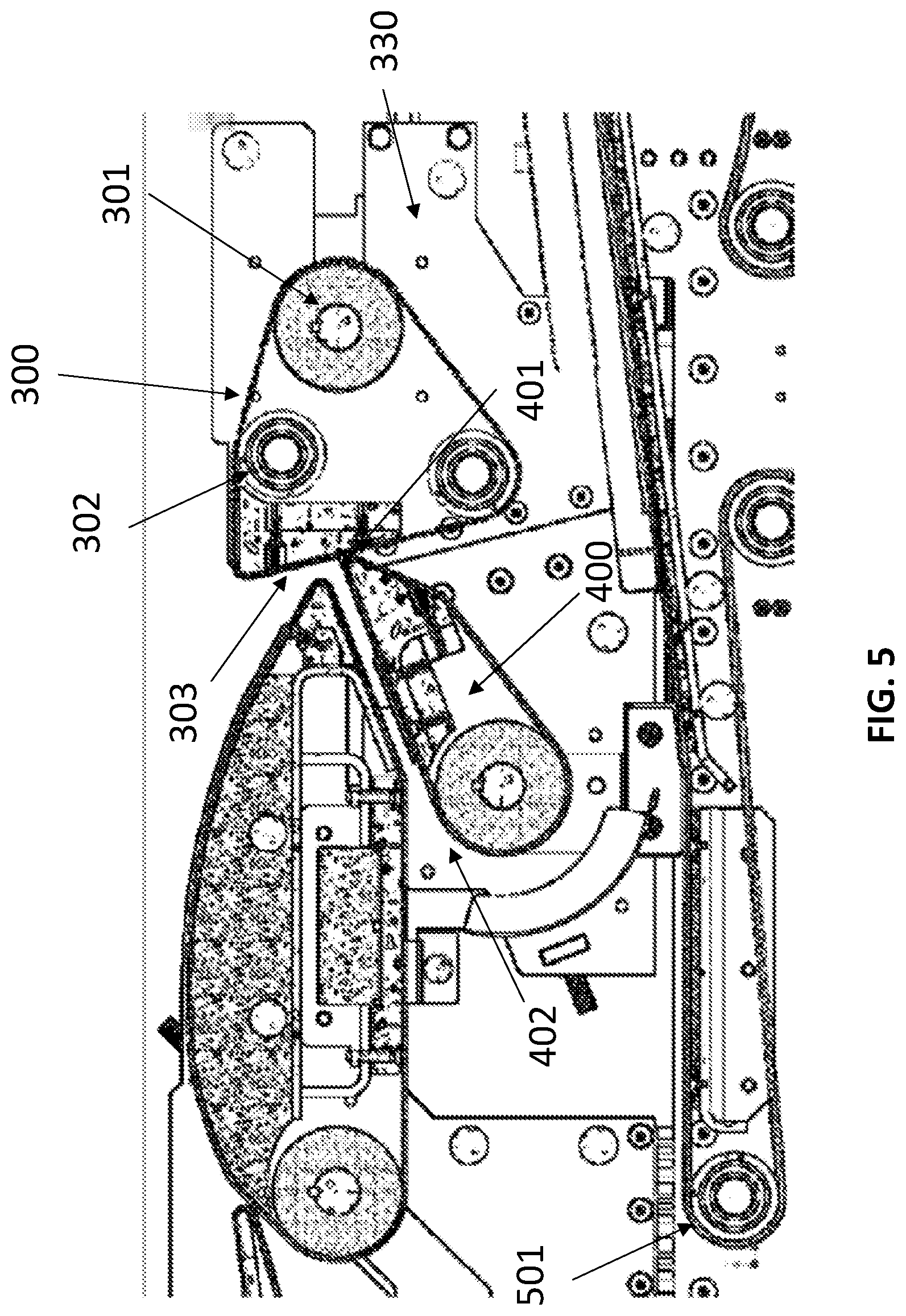
[0011] FIG. 5 shows the conveyor band, the start rolling band and the rolling band of the roller system for laminated products of present invention in detail.
[0012] FIG. 6 shows the embodiment where the feeding band is in direct communication with the unloading band.
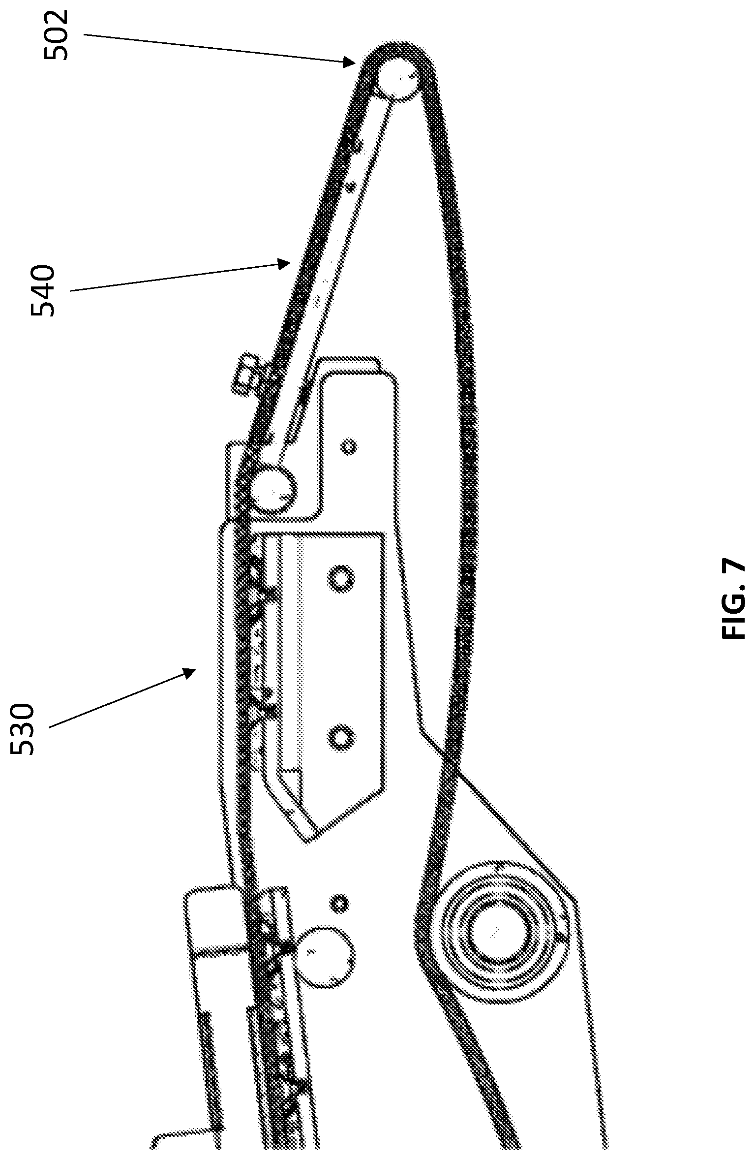
[0013] FIG. 7 shows the final end of the unloading band in detail.
DETAILED DESCRIPTION OF THE INVENTION
[0014] The following description makes references to FIGS. 1 through 7 in an indistinctive manner.
[0015] The use of the term "approximately" provides a determined additional range. The term is defined in the following manner. The additional range provided by the term is .+-.10%. By way of example, but not in a limitative manner, if it states "approximately between 25.degree. and 41.degree.", the exact range lies between 22.5.degree. and 45.1.degree., or yet between 27.5.degree. and 45.1.degree., or yet between 22.5 and 36.9.degree. or between 27.5.degree. and 36.9.degree.. Any of the possibilities described above are covered through the use of the term "approximately".
[0016] Present invention refers to a roller system (10) for laminated products based on any type of mass and/or combination of them. Said rolling system (10) is found set in a main support: structure (20).
[0017] The roller system (10) presents a feeding band (100), which presents an entrance end (101) as well as an exit end (102), said feeding band (100) is found partially mounted unto a first mobile support structure (110), the feeding band (100) presents a dumping movement at the exit end (102), in such a way that the first support structure presents a pivot (111) near the entrance end (101) of the feeding band (100), in such a way that the first mobile support structure (110) moves with regard to the main support structure (20), said feeding band (100) presents a plurality of tracking rolling pins, a tightening rolling pin and a driving rolling pin, the tightening rolling pin and the driving rolling pin are found set in the first support structure (110), while the tracking rolling pins are distributed between the first support structure (110) and the main support structure (20); said tightening rolling pin is vertically displaced in a groove set on a lateral wall of the first support structure (110).
[0018] The exit end (102) of the feeding band (100) is found overlapped with the entrance end (201) of a conveyor band (200); said conveyor band (200) presents a horizontal parabolic shape, preferably convex on the upper part of the main support structure (20), said conveyor band (200) presents an exit end (202) opposite to an entrance end (201), a plurality of tracking rolling pins, a tightening rolling pin and a driving rolling pin, the tightening rolling pin is angularly displaced to tighten the conveyor band and in this way ensure its correct functioning, said displacement is undertaken preferably, by means of a first servo motor.
[0019] The exit end (202) of the conveyor band (200) is found in communication with the work surface (303) of a start roller band (300) set on an inclined plane towards the conveyor band (200), in such a way that it presents an inclination from between approximately 95.degree. to approximately 120.degree., said start roller band (300) comprises a driving roller pin (301) and at least two tracking pins (302); said start rolling band (300) has the capability of displacing itself to at least one of a speed and a direction different from those of the conveyor band (200), the above in order to be able to undertake different types of rolling for the laminated products (1), said start rolling band (300) is found mounted unto a second mobile support structure (330), said mobile support structure (330) is found supported on a longitudinal guiding rail set on the main support structure (20) to longitudinally move the start roller band (300) in regards to the conveyor band (200), in such a way that said start roller band approaches/moves away from the conveyor band (200), this adjustment allows obtaining the desired aperture on the rolled product (2), this adjustment is crucial for achieving the rolling of the product, and is undertaken, preferably by means of a second servo motor.
[0020] A roller band (400) set on a descending inclined plane which presents an entrance end (401) and an exit end (402), the roller band (400) comprising a plurality of tracking rolling pins, and a tightening-driving rolling pin; the entry end (401) is found at a point which is higher than the exit end (402), similarly, said entrance end (401) is found under the exit end (102) of the conveyor band (200) and nearby to the work surface (301) of the start roller band; said roller band (400) is found mounted unto a third mobile support structure which is found mounted unto a vertical guiding rail, said vertical guiding rail is found mounted unto the second mobile support structure (330), in such a way that said roller band (400) moves vertically in relation to the start rolling hand (300), this adjustment allows the roller band to approach or move way towards the return of the unloading band (500). This adjustment allows ensuring and maintaining the desired aperture in the rolled product (2), and is undertaken, preferably by means of a third servo motor.
[0021] Given that the second and third mobile support structures (330) are found connected, upon the start roller band (300) approaching/moving away from the conveyor band (200), consequently, the roller band (400) also is approaching/moving away from said conveyor band (200), so that said roller band (400) has two movements, one being a vertical movement and the other a longitudinal movement.
[0022] An unloading band (500) which receives the laminated product (1) once it is rolled from the roller band (400), in addition to feeding the rolled product (2) to the next step of the process, whether it is baking or frying. Said band comprises an entrance end (501) and an exit end (502), a plurality of tracking rolling pins and one tightening-driving rolling pin, said unloading band (500) is found mounted unto the main support structure (20).
[0023] Said unloading band (500) presents at least four sections with different inclinations, a first section (510) with a substantially horizontal inclination, a second section (520) with an ascending inclination, a third section (530) with a substantially horizontal inclination and a fourth section (540) with a descending inclination, set on the lower part of the main support structure, which unrolls the rolled products.
[0024] In an additional embodiment, the feeding band (100) presents a length and a capability of being able to pivot, which allows transferring the laminated material without rolling from a laminated system (30) to the next step of the process, in such a way that the laminated material is not rolled.
[0025] Said feeding hand (100), when found at its lowest point, allows that: the exit end (102) is found in contact with the entrance end of the unloading band (500), given the pivot (111) which is in close proximity to the entrance end (101) of the feeding band (100) which goes up and down to establish contact with the exit of the laminated system.
[0026] Alterations to the structure hereby described for the present invention can be foreseen by those persons skilled in the art. However, it must be understood that present description is related with the preferred embodiments of the invention, which is merely for illustrative purposes and must not be construed as a limitation of present invention. All obvious modifications in the spirit: of the invention, such as changes to the shape, material and sizes of the different elements which make up the invention, must be considered to lie within the scope of the attached claims.
* * * * *
D00000
D00001
D00002
D00003
D00004
D00005
D00006
D00007
XML
uspto.report is an independent third-party trademark research tool that is not affiliated, endorsed, or sponsored by the United States Patent and Trademark Office (USPTO) or any other governmental organization. The information provided by uspto.report is based on publicly available data at the time of writing and is intended for informational purposes only.
While we strive to provide accurate and up-to-date information, we do not guarantee the accuracy, completeness, reliability, or suitability of the information displayed on this site. The use of this site is at your own risk. Any reliance you place on such information is therefore strictly at your own risk.
All official trademark data, including owner information, should be verified by visiting the official USPTO website at www.uspto.gov. This site is not intended to replace professional legal advice and should not be used as a substitute for consulting with a legal professional who is knowledgeable about trademark law.