Radical Assist Ignition Plasma System And Method
Sekiguchi; Hiroo
U.S. patent application number 16/930193 was filed with the patent office on 2021-01-21 for radical assist ignition plasma system and method. The applicant listed for this patent is ASM IP Holding B.V.. Invention is credited to Hiroo Sekiguchi.
| Application Number | 20210020467 16/930193 |
| Document ID | / |
| Family ID | 1000005000906 |
| Filed Date | 2021-01-21 |


| United States Patent Application | 20210020467 |
| Kind Code | A1 |
| Sekiguchi; Hiroo | January 21, 2021 |
RADICAL ASSIST IGNITION PLASMA SYSTEM AND METHOD
Abstract
Plasma-assisted methods and apparatus are disclosed. The methods and apparatus can be used to provide activated species formed in a remote plasma unit to a reaction chamber to assist ignition of a plasma within a reaction chamber coupled to the remote plasma unit.
| Inventors: | Sekiguchi; Hiroo; (Tokyo, JP) | ||||||||||
| Applicant: |
|
||||||||||
|---|---|---|---|---|---|---|---|---|---|---|---|
| Family ID: | 1000005000906 | ||||||||||
| Appl. No.: | 16/930193 | ||||||||||
| Filed: | July 15, 2020 |
Related U.S. Patent Documents
| Application Number | Filing Date | Patent Number | ||
|---|---|---|---|---|
| 62875321 | Jul 17, 2019 | |||
| Current U.S. Class: | 1/1 |
| Current CPC Class: | H01J 37/32357 20130101; H01J 37/32422 20130101; H01J 2237/334 20130101; H01L 21/31122 20130101; H01L 21/67069 20130101; H01L 21/31138 20130101; H01L 21/0273 20130101; H01L 21/0337 20130101 |
| International Class: | H01L 21/67 20060101 H01L021/67; H01L 21/027 20060101 H01L021/027; H01L 21/033 20060101 H01L021/033; H01L 21/311 20060101 H01L021/311; H01J 37/32 20060101 H01J037/32 |
Claims
1. A method of forming patterned features on a substrate, the method comprising the steps of: providing the substrate within a reaction chamber; using a remote plasma unit, forming first activated species; providing the first activated species to the reaction chamber for a first time interval; and after initiating the step of providing the first activated species to the reaction chamber, forming second activated species within the reaction chamber for a second time interval, wherein the first time interval and the second time interval overlap.
2. The method of claim 1, further comprising a step of providing argon to the remote plasma unit.
3. The method of claim 1, wherein the substrate comprises features.
4. The method of claim 3, further comprising a step of trimming the features using the second activated species.
5. The method of claim 4, wherein the features comprise carbon.
6. The method of claim 5, wherein the features comprise one or more of photoresist, spin-on carbon (SOC) material, and carbon hard mask (CHM) material.
7. The method of claim 1, wherein the second reactive species are formed using a direct plasma.
8. The method of claim 1, wherein the step of forming the second reactive species comprises providing an oxygen-containing gas to the reaction chamber.
9. The method of claim 8, wherein the oxygen-containing gas comprises one or more gases selected from the group comprising O.sub.2, CO.sub.2, and N.sub.2O.
10. The method of claim 8, wherein the oxygen-containing gas is not supplied to the remote plasma unit.
11. A method of trimming features on a substrate, the method comprising the steps of: providing the substrate within a reaction chamber; using a remote plasma unit, forming first activated species; providing the first activated species to the reaction chamber for a first time interval; after initiating the step of providing the first activated species to the reaction chamber, forming second activated species within the reaction chamber for a second time interval, wherein the first time interval and the second time interval overlap; and trimming the features using the second activated species.
12. The method of claim 11, wherein a first gas is provided to the remote plasma unit to form the first activated species, a second gas is provided to the reaction chamber to form the second activated species, and wherein the first gas and the second gas are different.
13. The method of claim 11, wherein the features comprise carbon.
14. The method of claim 11, wherein the features comprise one or more of photoresist, spin-on carbon (SOC) material, and carbon hard mask (CHM) material.
15. The method of claim 11, wherein the step of forming second activated species comprises providing an oxygen-containing gas to the reaction chamber.
16. The method of claim 15, wherein the oxygen-containing gas comprises one or more gases selected from the group comprising O.sub.2, CO.sub.2, and N.sub.2O.
17. The method of claim 15, wherein the oxygen-containing gas is not supplied to the remote plasma unit.
18. The method of claim 11, wherein a pressure within the reaction chamber during the step of forming the second activated species is between about 200 and about 600 Pa.
19. The method of claim 11, wherein the first activated species comprise argon activated species.
20. A system configured to perform the method of claim 1.
Description
CROSS-REFERENCE TO RELATED APPLICATIONS
[0001] This application claims the benefit of U.S. Provisional Application No. 62/875,321, filed on Jul. 17, 2019, in the United States Patent and Trademark Office, the disclosure of which is incorporated herein in its entirety by reference.
FIELD OF INVENTION
[0002] The present disclosure generally relates to methods of forming device structures and to systems for forming the structures. More particularly, the disclosure relates to methods of using a plasma to form the devices and to systems with plasma reactors.
BACKGROUND OF THE DISCLOSURE
[0003] During the manufacture of electronic devices, fine patterns of features can be formed on a surface of a substrate by patterning the surface of the substrate and etching material from the substrate surface using, for example, plasma-assisted etching processes. As a density of devices on a substrate increases, it becomes increasingly desirable to form features with smaller dimensions.
[0004] Photoresist is often used to pattern a surface of a substrate prior to etching. A pattern can be formed in the photoresist by applying a layer of photoresist to a surface of the substrate, masking the surface of the photoresist, exposing the unmasked portions of the photoresist to radiation, such as ultraviolet light or an electron beam, and removing a portion (e.g., the unmasked or masked portion) of the photoresist, while leaving a portion of the photoresist on the substrate surface.
[0005] After the removing step, excess residual photoresist can remain at the bottom or foot of a photoresist feature. This excess photoresist can cause deviations from desired patterns that are transferred from the photoresist to an underlying layer during a subsequent etching process.
[0006] Recently, formation of patterns, having resolution beyond what is typically available using only photoresist, has progressed by using spacers; such techniques include spacer-defined double patterning (SDDP) processes. In SDDP processes, feature patterns are formed as core materials using photoresist or spin-on carbon (SOC) at dimensions that may correspond to, for example, a resolution limit or near a resolution limit of a photoresist process. Sidewall spacers are then formed on sidewalls of the core materials. Thereafter, the core materials are removed, while maintaining the sidewall spacers, and the remaining sidewall spacers are used as masks for etching an underlying layer. With this technology, because a distance between the spacers can be smaller than a width of the sacrificing film, such as photoresist, fine patterns can be formed in the underlying layer, which can have widths narrower than the resolution limit of the photoresist process.
[0007] In order to precisely control the critical dimension (CD) of features being formed using patterned core material, such as photoresist, dimension control of the core materials is desired. Trimming technology using plasma treatment, for example, is available for removing a portion of the core materials, such as excess material at the foot of features.
[0008] Typically, during a trimming process, a plasma is created within a reaction chamber. Because of its relative ease of ignition, argon is often used to ignite the plasma within the reaction chamber. A power used to ignite the plasma can depend on several factors, such as type of gas used to form the plasma, pressure within the reaction chamber, spacing between electrodes within the reaction chamber, and the like. Therefore, it is often desirable to try to tune the plasma ignition power for each trimming condition.
[0009] Unfortunately, some conditions can include relatively high power to ignite the plasma. The high-power conditions may cause undesired damage to the core material during the plasma ignition step. Further, because of its dependence on other factors, typical plasma ignition processes can be relatively unstable and non-versatile. Accordingly, improved methods and systems for igniting plasmas and/or for trimming core material are desired.
[0010] Any discussion of problems and solutions set forth in this section has been included in this disclosure solely for the purpose of providing a context for the present disclosure, and should not be taken as an admission that any or all of the discussion was known at the time the invention was made.
SUMMARY OF THE DISCLOSURE
[0011] Various embodiments of the present disclosure relate to plasma-assisted methods and apparatus. While the ways in which various embodiments of the present disclosure address drawbacks of prior methods and systems are discussed in more detail below, in general, various embodiments of the disclosure provide improved methods that can be used to ignite a plasma within a reaction chamber. Various techniques described herein provide reliable methods for igniting a plasma within a reaction chamber and/or methods for reducing damage to material (e.g., patterned material, such as photoresist) on a substrate surface.
[0012] In accordance with at least one embodiment of the disclosure, a method (e.g., of forming patterned features on a substrate) includes forming patterned features on a substrate. Exemplary methods can include the steps of: providing the substrate within a reaction chamber; using a remote plasma unit, forming first activated species; providing the first activated species to the reaction chamber for a first time interval; and after initiating the step of providing the first activated species to the reaction chamber, forming second activated species within the reaction chamber for a second time interval. The first time interval and the second time interval can overlap, such that the first activated species assists in igniting a plasma used to form the second activated species. The substrate may include features formed of, for example, carbon-containing material, such as one or more of photoresist, spin-on carbon (SOC) material, and carbon hard mask (CHM) material. The second activated species can be used to trim the features. The step of forming the second reactive species can include providing an oxygen-containing gas to the reaction chamber. The oxygen-containing gas can include, for example, one or more gases selected from the group comprising O.sub.2, CO.sub.2, and N.sub.2O. The remote plasma unit may be supplied with an inert gas, such as argon, to form the first activated species. The oxygen-containing gas may not be supplied to the remote plasma unit. A first gas can be provided to the remote plasma unit to form the first activated species. A second gas can be provided to the reaction chamber to form the second activated species. The first gas and the second gas can be different.
[0013] In accordance with yet further exemplary embodiments of the disclosure, a method of trimming features on a substrate is provided. The method of trimming features on a substrate can include providing the substrate within a reaction chamber; using a remote plasma unit, forming first activated species; providing the first activated species to the reaction chamber for a first time interval; after initiating the step of providing the first activated species to the reaction chamber, forming second activated species within the reaction chamber for a second time interval, and trimming the features using the second activated species. The first time interval and the second time interval can overlap, such that the first activated species assists in igniting a plasma used to form the second activated species. The features can be formed of, for example, carbon-containing material, such as one or more of photoresist, spin-on carbon (SOC) material, and carbon hard mask (CHM) material. The step of forming the second reactive species can include providing an oxygen-containing gas to the reaction chamber. The oxygen-containing gas can include, for example, one or more gases selected from the group comprising O.sub.2, CO.sub.2, and N.sub.2O. The remote plasma unit may be supplied with an inert gas, such as argon, to form the first (e.g., argon) activated species. The oxygen-containing gas may not be supplied to the remote plasma unit.
[0014] In accordance with yet additional examples of the disclosure, a deposition apparatus configured to perform a method as described herein is provided.
[0015] In accordance with yet further exemplary embodiments of the disclosure, a structure comprises a layer and/or features formed according to a method described herein.
[0016] These and other embodiments will become readily apparent to those skilled in the art from the following detailed description of certain embodiments having reference to the attached figures; the invention not being limited to any particular embodiment(s) disclosed.
BRIEF DESCRIPTION OF THE DRAWING FIGURES
[0017] A more complete understanding of exemplary embodiments of the present disclosure can be derived by referring to the detailed description and claims when considered in connection with the following illustrative figures.
[0018] FIG. 1 illustrates a timing sequence diagram.
[0019] FIGS. 2 and 3 illustrate a reactor system in accordance with at least one embodiment of the disclosure.
[0020] FIG. 4 illustrates a timing sequence diagram in accordance with at least one embodiment of the disclosure.
[0021] FIG. 5 illustrates ignition test results using a method in accordance with at least one embodiment of the disclosure.
[0022] FIGS. 6 and 7 illustrate a comparison of photoresist damage between a method in accordance with at least one embodiment of the disclosure and another process.
[0023] FIG. 8 illustrates ignition delay.
[0024] FIG. 9 illustrates ignition power as a function of pressure within a reaction chamber.
[0025] It will be appreciated that elements in the figures are illustrated for simplicity and clarity and have not necessarily been drawn to scale. For example, the dimensions of some of the elements in the figures may be exaggerated relative to other elements to help improve understanding of illustrated embodiments of the present disclosure.
DETAILED DESCRIPTION OF EXEMPLARY EMBODIMENTS
[0026] Although certain embodiments and examples are disclosed below, it will be understood by those in the art that the invention extends beyond the specifically disclosed embodiments and/or uses of the invention and obvious modifications and equivalents thereof. Thus, it is intended that the scope of the invention disclosed should not be limited by the particular disclosed embodiments described below.
[0027] The present disclosure generally relates to plasma-assisted methods and apparatus. As described in more detail below, exemplary methods can be used to facilitate plasma ignition within a reaction chamber; reduce damage, e.g., during a plasma ignition process, to material on a substrate surface; improve material removal rate uniformity across a surface of a substrate; and the like. The methods and apparatus described herein can be used to trim features on a substrate surface.
[0028] In this disclosure, "gas" may include material that is a gas at room temperature and pressure, a vaporized solid and/or a vaporized liquid, and may be constituted by a single gas or a mixture of gases, depending on the context. A gas other than the process gas, i.e., a gas introduced without passing through a gas distribution assembly, such as a showerhead, other gas distribution device, or the like, may be used for, e.g., sealing the reaction space, and may include a seal gas, such as a rare gas. The term "inert gas" refers to a gas that does not take part in a chemical reaction and/or a gas that excites a precursor when RF power is applied.
[0029] As used herein, the term "substrate" may refer to any underlying material or materials that may be used to form, or upon which, a device, a circuit, or a film may be formed. A substrate can include a bulk material, such as silicon (e.g., single-crystal silicon), other Group IV materials, such as germanium, or compound semiconductor materials, such as GaAs, and can include one or more layers overlying or underlying the bulk material. Further, the substrate can include various features, such as recesses, lines, and the like formed within or on at least a portion of a layer of the substrate. In accordance with exemplary aspects of the disclosure, one or more of the features are formed of a carbon-containing material, such as one or more of photoresist, spin-on carbon (SOC) material, and carbon hard mask (CHM) material. The features can be formed overlying an underlayer, an adhesion layer or film, or the like.
[0030] In some embodiments, "film" refers to a layer extending in a direction perpendicular to a thickness direction to cover an entire target or concerned surface, or simply a layer covering a target or concerned surface. In some embodiments, "layer" refers to a structure having a certain thickness formed on a surface or a synonym of film or a non-film structure. A film or layer may be constituted by a discrete single film or layer having certain characteristics or multiple films or layers, and a boundary between adjacent films or layers may or may not be clear and may or may not be established based on physical, chemical, and/or any other characteristics, formation processes or sequence, and/or functions or purposes of the adjacent films or layers.
[0031] Further, in this disclosure, any two numbers of a variable can constitute a workable range of the variable, and any ranges indicated may include or exclude the endpoints. Additionally, any values of variables indicated (regardless of whether they are indicated with "about" or not) may refer to precise values or approximate values and include equivalents, and may refer to average, median, representative, majority, etc. in some embodiments. Further, in this disclosure, the terms "including," "constituted by" and "having" refer independently to "typically or broadly comprising," "comprising," "consisting essentially of," or "consisting of" in some embodiments. In this disclosure, any defined meanings do not necessarily exclude ordinary and customary meanings in some embodiments.
[0032] In this disclosure, "continuously" can refer to one or more of without breaking a vacuum, without interruption as a timeline, without any material intervening step, without changing treatment conditions, immediately thereafter, as a next step, or without an intervening discrete physical or chemical structure between two structures other than the two structures in some embodiments.
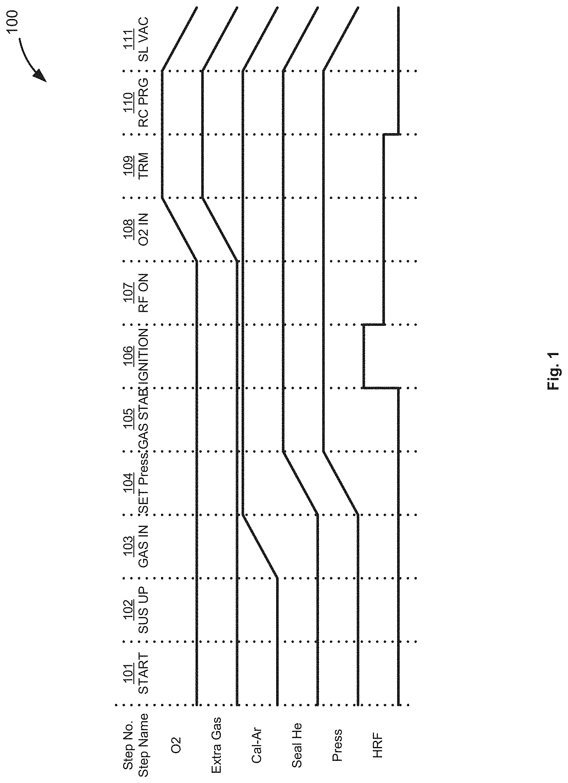
[0033] Turning now to the figures, FIG. 1 illustrates a conventional timing sequence 100 for a trimming process. Timing sequence 100 includes the steps of starting (step 101), raising the susceptor (step 102), introducing gas to a reaction chamber (step 103), setting the pressure (step 104), stabilizing gas flow (step 105), igniting the plasma (step 106), providing RF power (step 107), providing reactant gas (step 108), performing trimming (step 109), purging the reaction chamber (step 110), and reducing pressure within the reaction chamber (step 111).
[0034] During step 101, a substrate can be loaded onto a susceptor within a reaction chamber. Once the substrate is loaded onto the susceptor, a gate valve can be closed and the susceptor can be moved to an operating position (step 102).
[0035] During step 103, an inert gas, such as argon, can be introduced to the reaction chamber. During step 104, a pressure can be allowed to raise to a desired operating pressure, and the flowrate of the inert gas can be set to a desired level. In addition, a rare gas, such as helium, can be supplied to a reactor including the reaction chamber to provide a gas curtain between a reaction space and another section of a reactor, such as a load/unload space. The gas flowrates and a pressure within the reaction chamber can be allowed to stabilize for a period of time (step 105).
[0036] During step 106, a plasma within the reaction chamber is ignited. During this period, a relatively high radio frequency (RF) power (e.g., about 90-130 W) can be applied to, for example, parallel plates within the reaction chamber to strike a plasma. Then, during step 107, the power is reduced to a process or operating level. At step 108, a reactant gas (oxygen) and extra or dilution gas (e.g., nitrogen) are provided to the reaction chamber. During step 109, features are trimmed using activated reactant species. At step 110, plasma generator power is turned off and the reaction chamber is purged. Pressure within the reaction chamber is then reduced during step 111.
[0037] As illustrated in FIG. 1, during step 106, the power supplied to the reaction chamber to ignite the plasma is relatively high, compared to the power level provided to the reaction chamber during the trimming process. The relatively high power can result in damage of features and/or a layer or film upon which the features are formed. Further, the relatively high power can result in relatively high within wafer non-uniformity of a trim process and/or feature height after the trim process. As set forth below, embodiments of the disclosure provide improved apparatus and methods to mitigate the power requirements, improve plasma ignition, improve plasma stability, and reduce feature and/or layer damage, particularly during a plasma ignition step.
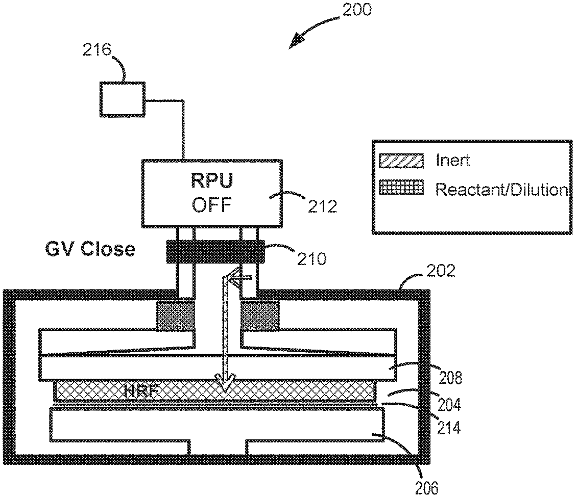
[0038] FIGS. 2 and 3 illustrate a reactor system 200 in accordance with exemplary embodiments of the disclosure. Reactor system 200 includes a reactor 202 including a reaction chamber 204, a susceptor 206, a gas distribution device 208, a gate valve 210, and a remote plasma unit (RPU) 212. FIG. 2 illustrates reactor system 200 when gate valve 210 is in a closed position and FIG. 3 illustrates reactor system 200 when gate valve 210 is in an open position.
[0039] Reactor 202 can include any suitable reactor. By way of example, a reactor system with a reactor suitable for use as reactor 202 is available from ASM International N.V.
[0040] Susceptor 206 can be capable of moving vertically to load and unload a substrate 214. Lift pins and a robot arm (not shown) can be used to load and unload the substrate from the surface of susceptor 206. Susceptor 206 can also form an electrode for forming a direct plasma within reaction chamber 204.
[0041] Gas distribution device 208 can include, for example, a showerhead gas distribution device. Further, gas distribution device 208 can form an electrode for forming a direct plasma within reaction chamber 204.
[0042] Gate valve 210 can be used to control a flux of activated species between RPU 212 and reaction chamber 204. Gate valve 210 can be open during a direct plasma ignition step and can be open or closed during a processing (e.g., trimming) step.
[0043] RPU 212 can include any suitable remote plasma unit. In accordance with examples of the disclosure, RPU 212 is coupled to an inert gas source 216, such that inert gas from the inert gas source can be supplied to RPU 212, and RPU 212 can generate activated species from the inert gas. Examples of suitable inert gases include argon. A power used to generate the remote plasma can be any power suitable to produce a plasma.
[0044] FIG. 4 illustrates an exemplary timing sequence 400 in accordance with exemplary embodiments of the disclosure. Timing sequence 400 can be used to perform various methods as described herein, including methods of forming patterned features on a substrate and methods of trimming features on a substrate, as described herein. System 200 can be used to perform the timing sequence and/or methods as described herein.
[0045] Timing sequence 400 includes the steps of starting (step 401), raising the susceptor (step 402), introducing gas to a reaction chamber (step 403), setting the pressure (step 404), stabilizing gas flow (step 405), remotely generating activated species (step 406), providing RF power for a direct plasma and trimming (step 407), purging the reaction chamber (step 408), and reducing pressure within the reaction chamber (step 409).
[0046] Similar to step 101, during step 401, a substrate can be loaded onto a susceptor within a reaction chamber. Once the substrate is loaded onto the susceptor, a reaction chamber gate valve can be closed and the susceptor can be moved to an operating position (step 402).
[0047] During step 403, an inert gas, such as argon can be introduced to an RPU, such as RPU 212. In addition, a gas, such as a dilution gas (e.g., nitrogen or argon, labeled "Extra Gas"), a reactant, such as one or more of O.sub.2, CO.sub.2, and N.sub.2O, and an inert gas (RC-inert) can be supplied to a reaction chamber--e.g., reaction chamber 204.
[0048] During step 404, a pressure can be allowed to rise to a desired operating pressure, and the flowrate of the gas to the reaction chamber and the flowrate of the gas to the RPU can be set to desired levels. During step 404, a rare gas, such as helium, can also be supplied to a reactor to, for example, provide a gas curtain between a reaction space and another section of a reactor, such as a load/unload section of the reactor. The gas flowrates and a pressure within the reaction chamber and/or RPU can be allowed to stabilize for a period of time (step 405).
[0049] During step 406, power is supplied to an RPU and/or activated species from the RPU are introduced into a reaction chamber. The (e.g., first) activated species from the RPU are provided to the reaction chamber to facilitate ignition of a direct plasma within the reaction chamber at a lower power and/or in a more stable manner than would be done without the assistance of the activated species from the RPU. In some cases, the RPU can be on constantly, and activated species can be provided to a reaction chamber by opening a gate valve between the RPU and the reaction chamber. Or, as illustrated, the RPU can be on only during steps 406 and optionally step 407.
[0050] During step 407, a process, such as a trimming process is performed within a reaction chamber. During this step, power is supplied to electrodes (e.g., gas distribution device 208 and/or susceptor 206 (if power is supplied to only one electrode, the other electrode may be grounded)) to form second activated species within the reaction chamber. During step 407, a power used to ignite the direct plasma within the reaction chamber can be about the same (e.g., within about ten percent) of the power used to maintain the plasma during step 407.
[0051] At step 408, plasma generator power for the direct plasma is turned off and optionally the power for the RPU is turned off and the reaction chamber is purged. As illustrated in FIG. 4, the reaction chamber can be purged by flowing one or more of the RPU-inert gas to the RPU and/or gas comprising one or more of the reactant, extra gas, reaction chamber (RC) inert gas, in any combination to the reaction chamber. Pressure within the reaction chamber can then be reduced during step 409. Table 1 below illustrates exemplary process conditions for steps 406 and 407.
[0052] Table 1 below illustrates exemplary process conditions for steps 406 and 407.
TABLE-US-00001 TABLE 1 Conditions for Steps 406 and 407 Pressure 200-600 Pa Substrate temperature 75-100.degree. C. RPU inert gas Ar Flowrate RPU inert gas 0.5-10.0 slm Flowrate of reactant 0.2-6.0 slm Flowrate of extra gas N.sub.2, Ar 0.0-6.0 slm Flowrate of reaction 0.5 slm chamber inert gas Flowrate of sealing gas 0.2-2.0 slm Reaction chamber pressure 200-600 Pa during trim process RPU power Suitable to produce remote plasma Direct plasma power 20-60 W Distance between electrodes 7.5-15.0 mm Duration of step 406 0.5-2.0 sec Duration of step 407 variable
[0053] The above-indicated power for a 300-mm wafer can be converted to W/cm.sup.2 (wattage per unit area of a wafer) which can apply to a wafer having a different diameter such as 200 mm or 450 mm. The substrate temperature can be considered to be a temperature of the reaction space during a process.
[0054] FIG. 5 illustrates advantages of exemplary methods compared to traditional methods that do not include radical assist ignition. The results in FIG. 5 illustrate ignition test results for 20 ignition tests. RAI indicates tests run with radial assist ignition (RAI) and w/o RAI indicates tests run without the assistance of RAI. As illustrated, use of radical assist ignition significantly reduced a number of mis-ignitions (e.g., no plasma formed), reduced or eliminated ignition delays (e.g., ignition delay of greater or equal to than 0.1 seconds), and/or provided good ignition (plasma forms) for the conditions set forth above in Table 1.
[0055] FIGS. 6 and 7 illustrate results of methods described herein when used to trim features, such as photoresist features, on a surface of a substrate. As illustrated in FIG. 6, an amount of feature (e.g., photoresist) damage (etch) without a reactant present can be significantly reduced using methods as described herein. FIG. 7 illustrates that a one sigma (standard deviation) within wafer uniformity of feature damage without the reactant present can be significantly reduced using methods as described herein.
[0056] FIG. 8 illustrates ignition delay, which is defined as delay time over 0.1 seconds. Without RAI, the ignition delay frequency was about 100%. However, with RAI, in accordance with examples of the present disclosure--e.g., using the conditions set forth in Table 1, the ignition delay was zero or about zero percent.
[0057] FIG. 9 illustrates that power for ignition generally increases with pressure within a reaction chamber up to a pressure of about 360 Pa. In the illustrated example, the power saturates at about 20 W for the conditions set forth in Table 1.
[0058] The example embodiments of the disclosure described above do not limit the scope of the invention, since these embodiments are merely examples of the embodiments of the invention. Any equivalent embodiments are intended to be within the scope of this invention. Indeed, various modifications of the disclosure, in addition to the embodiments shown and described herein, such as alternative useful combinations of the elements described, may become apparent to those skilled in the art from the description. Such modifications and embodiments are also intended to fall within the scope of the appended claims.
* * * * *
D00000
D00001
D00002
D00003
D00004
D00005
D00006
D00007
XML
uspto.report is an independent third-party trademark research tool that is not affiliated, endorsed, or sponsored by the United States Patent and Trademark Office (USPTO) or any other governmental organization. The information provided by uspto.report is based on publicly available data at the time of writing and is intended for informational purposes only.
While we strive to provide accurate and up-to-date information, we do not guarantee the accuracy, completeness, reliability, or suitability of the information displayed on this site. The use of this site is at your own risk. Any reliance you place on such information is therefore strictly at your own risk.
All official trademark data, including owner information, should be verified by visiting the official USPTO website at www.uspto.gov. This site is not intended to replace professional legal advice and should not be used as a substitute for consulting with a legal professional who is knowledgeable about trademark law.