Key Assembly And Keyboard Including The Same
Chen; Chun-Lin ; et al.
U.S. patent application number 16/923063 was filed with the patent office on 2021-01-21 for key assembly and keyboard including the same. This patent application is currently assigned to LITE-ON ELECTRONICS (GUANGZHOU) LIMITED. The applicant listed for this patent is LITE-ON ELECTRONICS (GUANGZHOU) LIMITED, Lite-On Technology Corporation. Invention is credited to Chun-Lin Chen, Jui-Yu Wu, Po-Hsiang Yu.
| Application Number | 20210020391 16/923063 |
| Document ID | / |
| Family ID | 1000004977512 |
| Filed Date | 2021-01-21 |


| United States Patent Application | 20210020391 |
| Kind Code | A1 |
| Chen; Chun-Lin ; et al. | January 21, 2021 |
KEY ASSEMBLY AND KEYBOARD INCLUDING THE SAME
Abstract
A key assembly including a base plate, a keycap, an elastic member, and a link member is provided. The base plate includes a body and a hook portion, the hook portion including a hole. The keycap is disposed on the base plate. The elastic member is disposed between the base plate and the keycap. The link member includes a connecting portion, a rod portion, and an end portion, the rod portion being assembled to the keycap, the connecting portion being connected between the rod portion and the end portion, and the end portion penetrating the hole, wherein an included angle between the end portion and the connecting portion is an obtuse angle.
| Inventors: | Chen; Chun-Lin; (Taipei, TW) ; Wu; Jui-Yu; (Taipei, TW) ; Yu; Po-Hsiang; (Taipei, TW) | ||||||||||
| Applicant: |
|
||||||||||
|---|---|---|---|---|---|---|---|---|---|---|---|
| Assignee: | LITE-ON ELECTRONICS (GUANGZHOU)
LIMITED GUANGZHOU CN Lite-On Technology Corporation Taipei TW |
||||||||||
| Family ID: | 1000004977512 | ||||||||||
| Appl. No.: | 16/923063 | ||||||||||
| Filed: | July 7, 2020 |
Related U.S. Patent Documents
| Application Number | Filing Date | Patent Number | ||
|---|---|---|---|---|
| 62875007 | Jul 17, 2019 | |||
| Current U.S. Class: | 1/1 |
| Current CPC Class: | H01H 13/14 20130101; H01H 13/10 20130101; H01H 13/7073 20130101 |
| International Class: | H01H 13/14 20060101 H01H013/14; H01H 13/7073 20060101 H01H013/7073; H01H 13/10 20060101 H01H013/10 |
Foreign Application Data
| Date | Code | Application Number |
|---|---|---|
| May 22, 2020 | CN | 202010440273.3 |
Claims
1. A key assembly, comprising: a base plate comprising a body and a hook portion, the hook portion comprising a hole; a keycap disposed on the base plate; an elastic member disposed between the base plate and the keycap; and a link member comprising a connecting portion, a rod portion, and an end portion, the rod portion being assembled to the keycap, the connecting portion being connected between the rod portion and the end portion, and the end portion penetrating the hole, wherein an included angle between the end portion and the connecting portion is an obtuse angle.
2. The key assembly according to claim 1, wherein the obtuse angle is greater than 90 degrees and less than or equal to 150 degrees.
3. The key assembly according to claim 1, further comprising: a membrane disposed between the base plate and the keycap, wherein the elastic member is disposed on the membrane.
4. The key assembly according to claim 3, wherein the membrane is a membrane circuit board.
5. The key assembly according to claim 1, wherein the base plate comprises a projection area corresponding to the end portion, the membrane comprises an opening, and the projection area and the opening at least partially overlap.
6. The key assembly according to claim 5, wherein a second end of the end portion relatively far away from the connecting portion abuts against the projection area, and a first end of the end portion connected to the connecting portion separated from the projection area by a distance in a vertical direction when the key assembly is not pressed.
7. The key assembly according to claim 1, wherein a size of the hole is 120% to 150% of a diameter of the end portion.
8. The key assembly according to claim 3, wherein the hook portion is a metal member integrally formed with the body.
9. The key assembly according to claim 1, wherein the hook portion is a plastic member and is formed on the body by insert molding.
10. A keyboard, comprising: a key assembly, comprising: a base plate comprising a body and a hook portion, the hook portion comprising a hole; a keycap disposed on the base plate; an elastic member disposed between the base plate and the keycap; and a link member comprising a connecting portion, a rod portion, and an end portion, the rod portion being assembled to the keycap, the connecting portion being connected between the rod portion and the end portion, and the end portion penetrating the hole, wherein an included angle between the end portion and the connecting portion is an obtuse angle.
11. The keyboard according to claim 10, wherein the obtuse angle is greater than 90 degrees and less than or equal to 150 degrees.
12. The keyboard according to claim 10, further comprising: a membrane disposed between the base plate and the keycap, wherein the elastic member is disposed on the membrane.
13. The keyboard according to claim 12, wherein the membrane is a membrane circuit board.
14. The keyboard according to claim 10, wherein the base plate comprises a projection area corresponding to the end portion, the membrane comprises an opening, and the projection area and the opening at least partially overlap.
15. The keyboard according to claim 14, wherein a second end of the end portion relatively far away from the connecting portion abuts against the projection area, and a first end of the end portion connected to the connecting portion separated from the projection area by a distance in a vertical direction when the key assembly is not pressed.
16. The keyboard according to claim 10, wherein a size of the hole is 120% to 150% of a diameter of the end portion.
17. The keyboard according to claim 12, wherein the hook portion is a metal member integrally formed with the body.
18. The keyboard according to claim 10, wherein the hook portion is a plastic member and is formed on the body by insert molding.
Description
CROSS-REFERENCE TO RELATED APPLICATION
[0001] This application claims the priority benefit of U.S. provisional application Ser. No. 62/875,007, filed on Jul. 17, 2019, and China application serial no. 202010440273.3, filed on May 22, 2020. The entirety of each of the above-mentioned patent applications is hereby incorporated by reference herein and made a part of this specification.
BACKGROUND OF THE INVENTION
1. Field of the Invention
[0002] The invention relates to a key assembly and a keyboard including the same.
2. Description of Related Art
[0003] In a general key assembly, an end of a link member will be inserted into a hook portion on a base plate. However, a gap is generated in a configuration of the key assembly because of an assembly tolerance between the hook portion and the link member. Therefore, when a keycap is pressed, the key assembly generates unpleasant sounds due to vibrations and collisions caused by actuation.
SUMMARY OF THE INVENTION
[0004] The invention relates to a key assembly capable of effectively reducing noise and a keyboard including the same.
[0005] According to an embodiment of the invention, the key assembly includes a base plate, a keycap, an elastic member, and a link member. The base plate includes a body and a hook portion, wherein the hook portion includes a hole. The keycap is disposed on the base plate. The elastic member is disposed between the base plate and the keycap. The link member includes a connecting portion, a rod portion, and an end portion, the rod portion being assembled to the keycap, the connecting portion being connected between the rod portion and the end portion, and the end portion penetrating the hole, wherein an included angle between the end portion and the connecting portion is an obtuse angle.
[0006] In the key assembly according to the embodiment of the invention, the obtuse angle is greater than 90 degrees and less than or equal to 150 degrees.
[0007] The key assembly according to the embodiment of the invention further includes a membrane disposed between the base plate and the keycap, wherein the elastic member is disposed on the membrane.
[0008] In the key assembly according to the embodiment of the invention, the membrane is a membrane circuit board.
[0009] In the key assembly according to the embodiment of the invention, the base plate includes a projection area corresponding to the end portion, the membrane includes an opening, and the projection area and the opening at least partially overlap.
[0010] In the key assembly according to the embodiment of the invention, a second end of the end portion relatively far away from the connecting portion abuts against the projection area, and a first end of the end portion connected to the connecting portion separated from the projection area by a distance in a vertical direction when the key assembly is not pressed.
[0011] In the key assembly according to the embodiment of the invention, a size of the hole is 120% to 150% of a diameter of the end portion.
[0012] In the key assembly according to the embodiment of the invention, the hook portion is a metal member integrally formed with the body.
[0013] In the key assembly according to the embodiment of the invention, the hook portion is a plastic member and is formed on the body by insert molding.
[0014] According to the embodiment of the invention, a keyboard including the foregoing key assembly is provided.
BRIEF DESCRIPTION OF THE DRAWINGS
[0015] The accompanying drawings are included to provide a further understanding of the invention, and are incorporated in and constitute a part of this specification. The drawings illustrate embodiments of the invention and, together with the description, serve to explain the principles of the invention.
[0016] FIG. 1 is a partial three-dimensional view of a key assembly according to an embodiment of the invention.
[0017] FIG. 2 is a cross-sectional view of the key assembly in FIG. 1.
[0018] FIG. 3 is a cross-sectional view of FIG. 1 from another view.
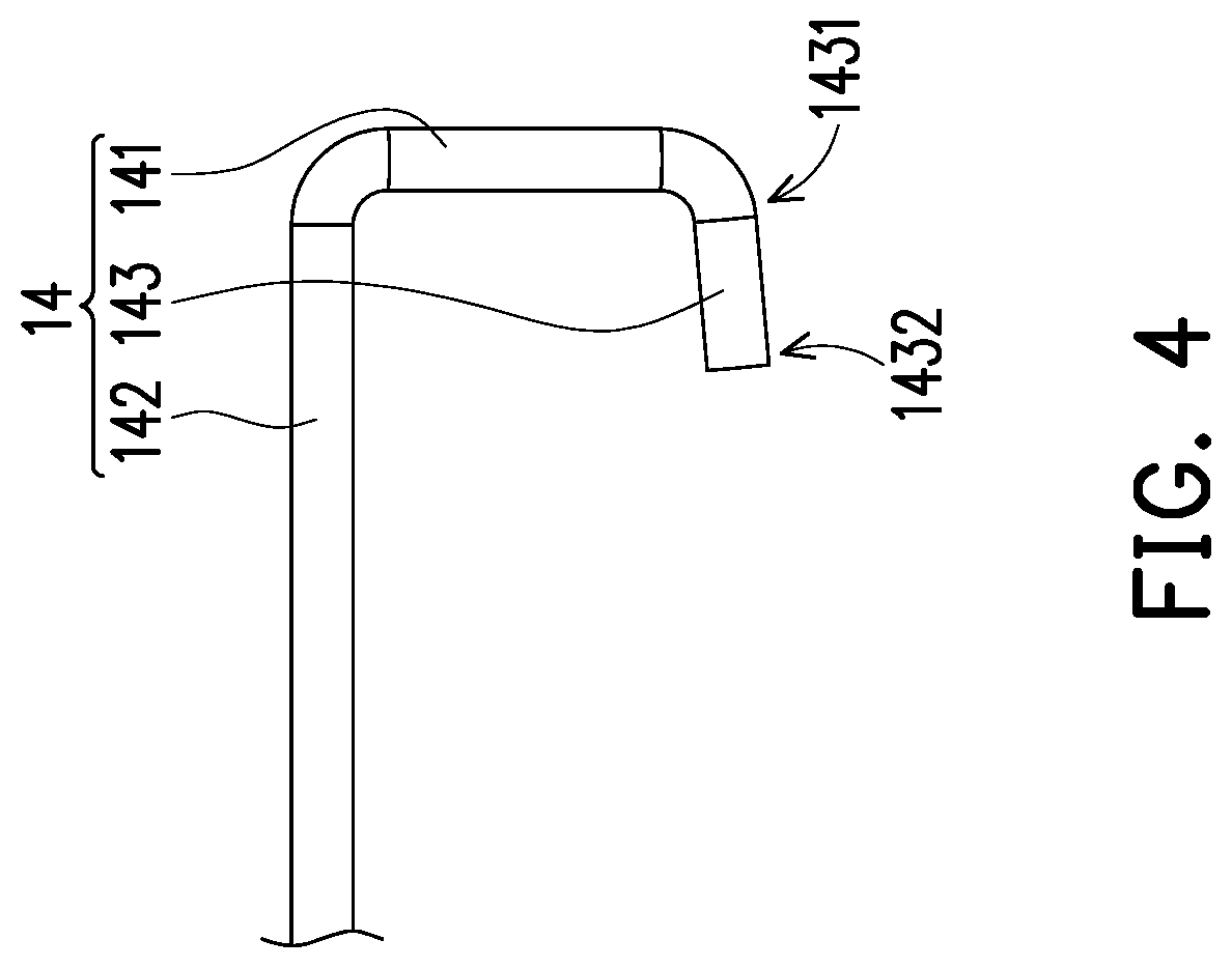
[0019] FIG. 4 is a schematic diagram of the link member in FIG. 1.
[0020] FIG. 5 is a schematic diagram of a key assembly when being pressed.
[0021] FIG. 6 is a schematic diagram of a key assembly according to a second embodiment of the invention.
[0022] FIG. 7 is a schematic diagram of a key assembly according to a third embodiment of the invention.
DESCRIPTION OF THE EMBODIMENTS
[0023] Exemplary embodiments of the invention are described in detail, and examples of the exemplary embodiments are shown in the accompanying drawings. Whenever possible, the same component symbols are used in the drawings and descriptions to indicate the same or similar parts.
First Embodiment
[0024] FIG. 1 is a partial three-dimensional view of a key assembly according to an embodiment of the invention, FIG. 2 is a cross-sectional view of the key assembly in FIG. 1, and FIG. 3 is a cross-sectional view of FIG. 1 from another view. Referring to FIG. 1, FIG. 2, and FIG. 3 together, the key assembly 10 is applied to a keyboard (not shown). The key assembly 10 includes a base plate 11, a keycap 12, an elastic member 13, and a link member 14. The base plate 11 includes a body 111 and a hook portion 112, the hook portion 112 having a hole 113. The keycap 12 is disposed on the base plate 11. The elastic member 13 is disposed between the base plate 11 and the keycap 12, and the elastic member 13 and the hook portion 112 are both located within an orthographic projection range of the keycap 12. The link member 14 includes a connecting portion 141, a rod portion 142, and an end portion 143. The rod portion 142 is assembled to the keycap 12, the connecting portion 141 is connected between the rod portion 142 and the end portion 143, and the end portion 143 penetrates the hole 113.
[0025] FIG. 4 is a schematic diagram of the link member 14 in FIG. 1. In particular, as shown in FIG. 4, an included angle .theta. between an end portion 143 of the link member 14 and a connecting portion 141 in the present embodiment is an obtuse angle, and the obtuse angle is preferable greater than 90 degrees and less than or equal to 150 degrees.
[0026] Still referring to FIG. 1, FIG. 2, and FIG. 3, for example, a body 111 of a base plate 11 in the present embodiment is made of a metal plate. In other embodiments not shown, the body 111 may be made of other materials such as glass fiber reinforced plates. In addition, in the present embodiment, the hook portion 112 is a plastic member and is formed on the body 111 by insert molding. However, in other embodiments not shown, the hook portion 112 may be integrally formed with the body 111. The body 111 has a projection area P corresponding to the end portion 143, and a size of the hole 113 is slightly greater than a diameter of the end portion 143 of the link member 14, which is preferably 120% to 150% of the diameter of the end portion 143.
[0027] Carrying on with the foregoing description, a key assembly 10 further includes a membrane 15 disposed between the base plate 11 and the keycap 12, wherein the membrane 15 is placed on the base plate 11, and the elastic member 13 is disposed on the membrane 15. The membrane 15 has an opening 151, wherein the hook portion 112 extends upward from the base plate 11 and passes through the opening 151, and the projection area P and the opening 151 at least partially overlap. In the present embodiment, the membrane 15 may be a membrane circuit board. However, in other implementations, the membrane 15 may be a separate member from the membrane circuit board. For example, the key assembly 10 may further include a membrane circuit board disposed under the base plate 11, and the base plate 11 is disposed between the membrane circuit board and the membrane 15. In some embodiments, the end portion 143 of the link member 14 may abut against an upper surface of the membrane 15 after penetrating into the hole 113, thereby reducing the sound during pressing. However, the invention is not limited thereto. In some embodiments, when the base plate 11 is made of a material with better sound absorption, the end portion 143 of the link member 14 may abut against the base plate 11 after penetrating into the hole 113.
[0028] The key assembly 10 further includes a support member 16 disposed between the keycap 12 and the base plate 11, where the support member 16 is also located within an orthographic projection range of the keycap 12.
[0029] Referring to FIG. 2, when the key assembly 10 is not pressed, in particular, since the included angle .theta. between the end portion 143 of the link member 14 and the connecting portion 141 is an obtuse angle, a second end 1432 of the end portion 143 relatively away from the connecting portion 141 abuts against the projection area P, and the end portion 143 connected to the first end 1431 of the connecting portion 141 is separated from the projection area P by a distance in a vertical direction. Specifically, a distance between the end portion 143 and the projection area P in the vertical direction gradually increases along a direction from the second end 1432 toward the first end 1431. In this case, the second end 1432 of the link member 14 is in contact with the projection area P of the base plate 11 with a point contact, and the first end 1431 of the end portion 143 of the link member 14 is in contact with the hook portion 112 in a manner of point contact.
[0030] FIG. 5 is a schematic diagram of a key assembly when being pressed. Referring to FIG. 1 and FIG. 5 together, when the key assembly 10 is pressed, a user exerts a force on the keycap 12, and the keycap 12 is forced to move downward, driving the elastic member 13 and the support member 16 to deform. In response to the movement of the keycap 12, the link member 14 rotates by using the second end 1432 of the end portion 143 as a rotation axis, wherein the second end 1432 abuts against the projection area P of the base plate 11. The rod portion 142 moves toward the base plate 11 from a position relatively away from the base plate 11, wherein the first end 1431 of the end portion 143 maintains contact with the hook portion 112.
[0031] However, when the force applied to the keycap 12 is removed, the elastic restoring force of the elastic member 13 drives the keycap 12 and the support member 16 to move upward and return to original positions. However, the link member 14 assembled to the keycap 12 is driven by the keycap 12 to rotate by using the second end 1432 of the end portion 143 as the rotation axis, wherein the second end 1432 abuts against the projection area P of the base plate 11, so that the rod portion 142 moves upward.
[0032] In particular, since the included angle .theta. between the end portion 143 of the link member 14 and the connecting portion 141 is an obtuse angle, the link member 14 rotates downward as the keycap 12 is pressed. Alternatively, when the force applied to the keycap 12 is removed, and the link member 14 rotates upward, the second end 1432 of the end portion 143 of the link member 14 maintains contact with the hook portion 112. Since the second end 1432 of the end portion 143 of the link member 14 always maintains contact with the hook portion 112, the link member 14 will not generate harsh sound due to vibration caused by disengagement from the hook portion 112 and springback of the link member 14 or collision with the hook portion 112. In other words, the key assembly 10 may be actuated quietly.
Second Embodiment
[0033] FIG. 6 is a schematic diagram of a key assembly according to a second embodiment of the invention. Referring to FIG. 6, the present embodiment and the foregoing first embodiments are substantially the same, and a difference is that: in the key assembly of the present embodiment, a connecting portion 241 and an end portion 243 of a link member 24 are disposed in pairs, and a rod portion 242 is connected between the pair of connecting portions 241. Specifically, a shape of the link member 24 is similar to a "C" shape.
Third Embodiment
[0034] FIG. 7 is a schematic diagram of a key assembly according to a third embodiment of the invention. Referring to FIG. 7, unlike the previous embodiment, a pair of link members 44 are used in a key assembly 40 of the present embodiment, and each of hook portions 412 of a base plate 41 has a pair of holes 413 for an end portion 443 of the link member 44 to correspondingly penetrate thereinto.
[0035] It may be learned from the foregoing that, in the key assembly of the invention and the keyboard including the same, the included angle between the end portion and the connecting portion of the link member is made obtuse, so that when the keycap of the key assembly is pressed or not pressed, the first end of the end portion of the link member always maintains contact with the hook portion, which may prevent the link member from generating harsh sound due to vibration caused by disengagement from the hook portion or springback of the link member or collision with the hook portion, effectively reducing noise that may be generated by the key assembly when being actuated.
[0036] It should be finally noted that the foregoing embodiments are merely intended for describing the technical solutions of the invention rather than limiting the invention. Although the invention is described in detail with reference to the foregoing embodiments, those of ordinary skill in the art should understand that they can still make modifications to the technical solutions described in the foregoing embodiments or make equivalent substitutions to some or all the technical features thereof, without departing from scope of the technical solutions of the embodiments of the invention.
* * * * *
D00000
D00001
D00002
D00003
D00004
D00005
D00006
D00007
XML
uspto.report is an independent third-party trademark research tool that is not affiliated, endorsed, or sponsored by the United States Patent and Trademark Office (USPTO) or any other governmental organization. The information provided by uspto.report is based on publicly available data at the time of writing and is intended for informational purposes only.
While we strive to provide accurate and up-to-date information, we do not guarantee the accuracy, completeness, reliability, or suitability of the information displayed on this site. The use of this site is at your own risk. Any reliance you place on such information is therefore strictly at your own risk.
All official trademark data, including owner information, should be verified by visiting the official USPTO website at www.uspto.gov. This site is not intended to replace professional legal advice and should not be used as a substitute for consulting with a legal professional who is knowledgeable about trademark law.