Variably Adjustable Stock For A Gun And Apparatus And Method For Adjustment Of Same
Faifer; Sagi
U.S. patent application number 17/000280 was filed with the patent office on 2021-01-21 for variably adjustable stock for a gun and apparatus and method for adjustment of same. The applicant listed for this patent is Sagi Faifer. Invention is credited to Sagi Faifer.
| Application Number | 20210018296 17/000280 |
| Document ID | / |
| Family ID | 1000005133302 |
| Filed Date | 2021-01-21 |


View All Diagrams
| United States Patent Application | 20210018296 |
| Kind Code | A1 |
| Faifer; Sagi | January 21, 2021 |
VARIABLY ADJUSTABLE STOCK FOR A GUN AND APPARATUS AND METHOD FOR ADJUSTMENT OF SAME
Abstract
A stock for a gun is disclosed which includes a butt stock body (12). The butt stock body may include a butt plate receptacle (108). The stock further may include a butt plate assembly (20) positioned in the butt plate receptacle (108), a cheek piece (18) releasably secured to the butt stock body (12) and the butt plate assembly (20), and a clamp (30). The stock may include first and second configurations such that in the first configuration the clamp permits independent movement of the butt plate assembly (20) and the cheek piece (18), and in the second configuration the clamp fixes movement of the butt plate assembly and the cheek piece relative to the butt stock body. The clamp (30) may be assembled within the stock body (12) to provide for variable adjustment of the butt stock with a dominant hand on the firearm grip.
| Inventors: | Faifer; Sagi; (Mishmar Hashiva, IL) | ||||||||||
| Applicant: |
|
||||||||||
|---|---|---|---|---|---|---|---|---|---|---|---|
| Family ID: | 1000005133302 | ||||||||||
| Appl. No.: | 17/000280 | ||||||||||
| Filed: | August 22, 2020 |
Related U.S. Patent Documents
| Application Number | Filing Date | Patent Number | ||
|---|---|---|---|---|
| 29698414 | Jul 16, 2019 | |||
| 17000280 | ||||
| 62890362 | Aug 22, 2019 | |||
| Current U.S. Class: | 1/1 |
| Current CPC Class: | F41C 23/14 20130101 |
| International Class: | F41C 23/14 20060101 F41C023/14 |
Claims
1. A stock for a gun comprising: a butt stock body including a first longitudinal axis, the butt stock body comprising a proximal end, a distal end spaced from the proximal end along the first longitudinal axis, and a butt plate receptacle situated adjacent to the proximal end; a butt plate assembly positioned in the butt plate receptacle; a cheek piece abutting the butt stock body and the butt plate assembly; and a clamp which comprises first and second configurations such that in the first configuration the clamp permits independent movement of the butt plate assembly and the cheek piece relative to the butt stock body, and such that in the second configuration the clamp fixes movement of the butt plate assembly and the cheek piece relative to the butt stock body.
2. The stock of claim 1, wherein in the second configuration the cheek piece is clamped against the butt stock body and the butt plate assembly.
3. The stock of claim 1, wherein the butt plate receptacle is housed in the butt stock body, the butt plate receptacle extending from the proximal end of the butt stock body toward the distal end of the butt stock body.
4. The stock of claim 3, wherein the butt plate receptacle comprises: a port side butt plate receptacle sidewall, a starboard side butt plate receptacle sidewall, and a lower rail receiving track disposed between the port side butt plate receptacle sidewall and the starboard side butt plate receptacle sidewall.
5. The stock of claim 4, wherein the port side butt plate receptacle sidewall comprises: a port side upper stop, a port side lower stop, and a port side opening.
6. The stock of claim 5, wherein the starboard side butt plate receptacle sidewall comprises: a starboard side upper stop, a starboard side lower stop, and a starboard side opening.
7. The stock of claim 4, wherein the butt plate receptacle further comprises a butt plate travel adjustment mechanism.
8. The stock of claim 7, wherein the butt plate travel adjustment mechanism comprises a screw and an adjustment knob.
9. The stock of claim 8, wherein the adjustment knob is disposed at an acute angle with respect to the lower rail receiving track and is connected to the screw by a mating screw thread such that rotation of the adjustment knob in a first direction advances the screw into the lower rail receiving track to selectively limit rearward travel of the butt plate assembly.
10. The stock of claim 1, wherein the butt plate assembly comprises a butt plate; a butt pad, and a cover plate disposed between the butt pad and the butt plate.
11. The stock of claim 10, wherein the butt pad comprises a butt plate fastener hole, the butt plate fastener hole being of an elongated shape having a first major axis, the first major axis being perpendicular to the first longitudinal axis.
12. The stock of claim 10, wherein the butt plate assembly further comprises a frame adjacent to the butt plate, the frame comprising: an upper rail which comprises a port side fluted upper rail face, a starboard side fluted upper rail face, a comb portion positioned between the port side fluted upper rail face and the starboard side fluted upper rail face, and a spring guide projecting from the comb portion; a lower rail which comprises a port side fluted lower rail face, and a starboard side fluted lower rail face; and a front rail which connects the upper rail and the lower rail.
13. The stock of claim 12, wherein the frame further comprises a passage located between the upper rail and the lower rail.
14. The stock of claim 12, wherein the butt plate assembly further comprises a port side clamping plate which comprises a first exterior oriented face; a first interior oriented face which comprises a first grooved portion, the first grooved portion being configured and dimensioned to engage with the port side fluted upper rail face, and a first elongated slot extending from the first exterior oriented face to the first interior oriented face, and a starboard side clamping plate which comprises a second exterior oriented face, a second interior oriented face which comprises a second grooved portion, the second grooved portion being configured and dimensioned to engage with the starboard side fluted upper rail face, and a second elongated slot, the second elongated slot being disposed opposite to the first elongated slot.
15. The stock of claim 14, wherein the port side clamping plate and the starboard side clamping plate are juxtaposed, and the frame is positioned between the port side clamping plate and the starboard side clamping plate.
16. The stock of claim 15, further comprising a first spring situated between the port side clamping plate and the starboard side clamping plate.
17. The stock of claim 16, wherein the frame, the port side clamping plate, and the starboard side clamping plate are positioned in the butt plate receptacle, and the first spring biases the port side clamping plate and the starboard side clamping plate away from the frame.
18. The stock of claim 17, wherein the butt stock assembly further comprises a second spring positioned around the spring guide, and the second spring biases the frame away from the distal end of the butt stock body.
19. The stock of claim 1, wherein the cheek piece comprises: a cheek rest, a first cheek rest riser connected to the cheek rest, and a second cheek rest riser connected to the cheek rest.
20. The stock of claim 19, wherein the clamp comprises: an eccentric lever positioned adjacent to the first cheek rest riser, an anchor positioned adjacent to the second cheek rest riser, and a locking rod arranged through the butt plate receptacle and the butt plate assembly, the locking rod being connected to the eccentric lever and the anchor such that in the second configuration the eccentric lever forms a first clamping member and the anchor forms a second clamping member for fixing movement of the butt plate assembly and the cheek piece relative to the butt stock body.
Description
CROSS REFERENCE TO RELATED APPLICATIONS
[0001] This application claims the benefit of U.S. Provisional Application No. 62/890,362 filed Aug. 22, 2019. Also, this application is a continuation-in-part of U.S. patent application Ser. No. 29/698,414 filed Jul. 16, 2019. These applications are incorporated by reference herein in their entirety.
FIELD OF THE INVENTION
[0002] The invention generally relates to a stock for a small arms weapon. More particularly, the invention relates to a variably adjustable butt stock for a firearm.
BACKGROUND
[0003] Stabilizing accessories for firearms are known in the related art. These accessories may be used to provide support for a firearm and may facilitate enhanced accuracy of the weapon during operation.
SUMMARY
[0004] Hence, a variably adjustable stock for a gun is disclosed. The stock may include a butt stock body. The butt stock body may include a first longitudinal axis as well as a proximal end, a distal end spaced from the proximal end along the first longitudinal axis, and a butt plate receptacle. The butt plate receptacle may be situated adjacent to the proximal end. The stock may further include a butt plate assembly positioned in the butt plate receptacle, a cheek piece abutting the butt stock body and the butt plate assembly, and a clamp. The clamp may include first and second configurations such that in the first configuration the clamp permits independent movement of the butt plate assembly and the cheek piece relative to the butt stock body. In the second configuration, the clamp may fix movement of the butt plate assembly and the cheek piece relative to the butt stock body. For instance, in the second configuration, the cheek piece may be clamped against the butt stock body and the butt plate assembly.
[0005] The butt plate receptacle may be housed in the butt stock body. The butt plate receptacle may extend from the proximal end of the butt stock body toward the distal end of the butt stock body. Additionally, the butt plate receptacle may include a port side butt plate receptacle sidewall, a starboard side butt plate receptacle sidewall, and a lower rail receiving track disposed between the port side butt plate receptacle sidewall and the starboard side butt plate receptacle sidewall. The port side butt plate receptacle sidewall further may include a port side upper stop, a port side lower stop, and a port side opening. Similarly, the starboard side butt plate receptacle sidewall may include a starboard side upper stop, a starboard side lower stop, and a starboard side opening. Also, the butt plate receptacle may include a butt plate travel adjustment mechanism. The butt plate travel adjustment mechanism may include a screw and an adjustment knob. The adjustment knob may be disposed at an acute angle with respect to the lower rail receiving track and may be connected to the screw by a mating screw thread such that rotation of the adjustment knob in a first direction advances the screw into the lower rail receiving track to selectively limit rearward travel of the butt plate assembly.
[0006] Additionally, the butt plate assembly may include a butt plate, a butt pad, and a cover plate disposed between the butt pad and the butt plate. The butt pad may include a butt plate fastener hole. The butt plate fastener hole may be of an elongated shape having a first major axis, the first major axis being perpendicular to the first longitudinal axis.
[0007] Further, the butt plate assembly may include a frame adjacent to the butt plate. The frame may include an upper rail. The upper rail may include a port side fluted upper rail face, a starboard side fluted upper rail face, a comb portion positioned between the port side fluted upper rail face and the starboard side fluted upper rail face, and a spring guide projecting from the comb portion. The frame may further include a lower rail. The lower rail may include a port side fluted lower rail face and a starboard side fluted lower rail face. Also, the frame may include a front rail which connects the upper rail and the lower rail. The frame further may include a passage located between the upper rail and the lower rail.
[0008] The butt plate assembly may further include a port side clamping plate. The port side clamping plate may include a first exterior oriented face and a first interior oriented face. The first interior oriented face may include a first grooved portion. The first grooved portion may be configured and dimensioned to engage with the port side fluted upper rail face. Also, the port side clamping plate may include a first elongated slot which extends from the first exterior oriented face to the first interior oriented face. Moreover, the butt plate assembly may include a starboard side clamping plate. The starboard side clamping plate may include a second exterior oriented face and a second interior oriented face. The second interior oriented face may include a second grooved portion. The second grooved portion may be configured and dimensioned to engage with the starboard side fluted upper rail face. Also, the starboard side clamping plate may include a second elongated slot, the second elongated slot being disposed opposite to the first elongated slot.
[0009] The port side clamping plate and the starboard side clamping plate may be juxtaposed, and the frame may be positioned between the port side clamping plate and the starboard side clamping plate. A first spring may be situated between the port side clamping plate and the starboard side clamping plate. The frame, the port side clamping plate, and the starboard side clamping plate may be positioned in the butt plate receptacle, and the first spring may bias the port side clamping plate and the starboard side clamping plate away from the frame. The butt stock assembly further may include a second spring that is positioned around the spring guide. The second spring may bias the frame away from the distal end of the butt stock body.
[0010] Furthermore, the cheek piece may include a cheek rest, a first cheek rest riser connected to the cheek rest, and a second cheek rest riser connected to the cheek rest. Additionally, the clamp may include an eccentric lever positioned adjacent to the first cheek rest riser, an anchor positioned adjacent to the second cheek rest riser, and a locking rod. The locking rod may be arranged through the butt plate receptacle and the butt plate assembly. The locking rod may be connected to the eccentric lever and the anchor such that in the second configuration the eccentric lever forms a first clamping member and the anchor forms a second clamping member for fixing movement of the butt plate assembly and the cheek piece relative to the butt stock body.
[0011] An apparatus and method are disclosed in which the clamp may be assembled within the stock body to provide for variable adjustment of the butt stock with a dominant hand on the firearm grip, as well as providing for variable adjustment of a butt stock with a nondominant hand. Similarly, a modular stock and one or more adaptors are disclosed which may be packaged as a kit for selectively assembling a left dominant hand configuration of a variably adjustable stock or a right dominant hand configuration of a variably adjustable stock, alone or with one or more adaptors for use with a specific firearm or receiver extension.
DESCRIPTION OF THE DRAWINGS
[0012] In the accompanying drawings, which form part of this specification and are to be read in conjunction therewith and in which like reference numerals are used to indicate like parts in the various views:
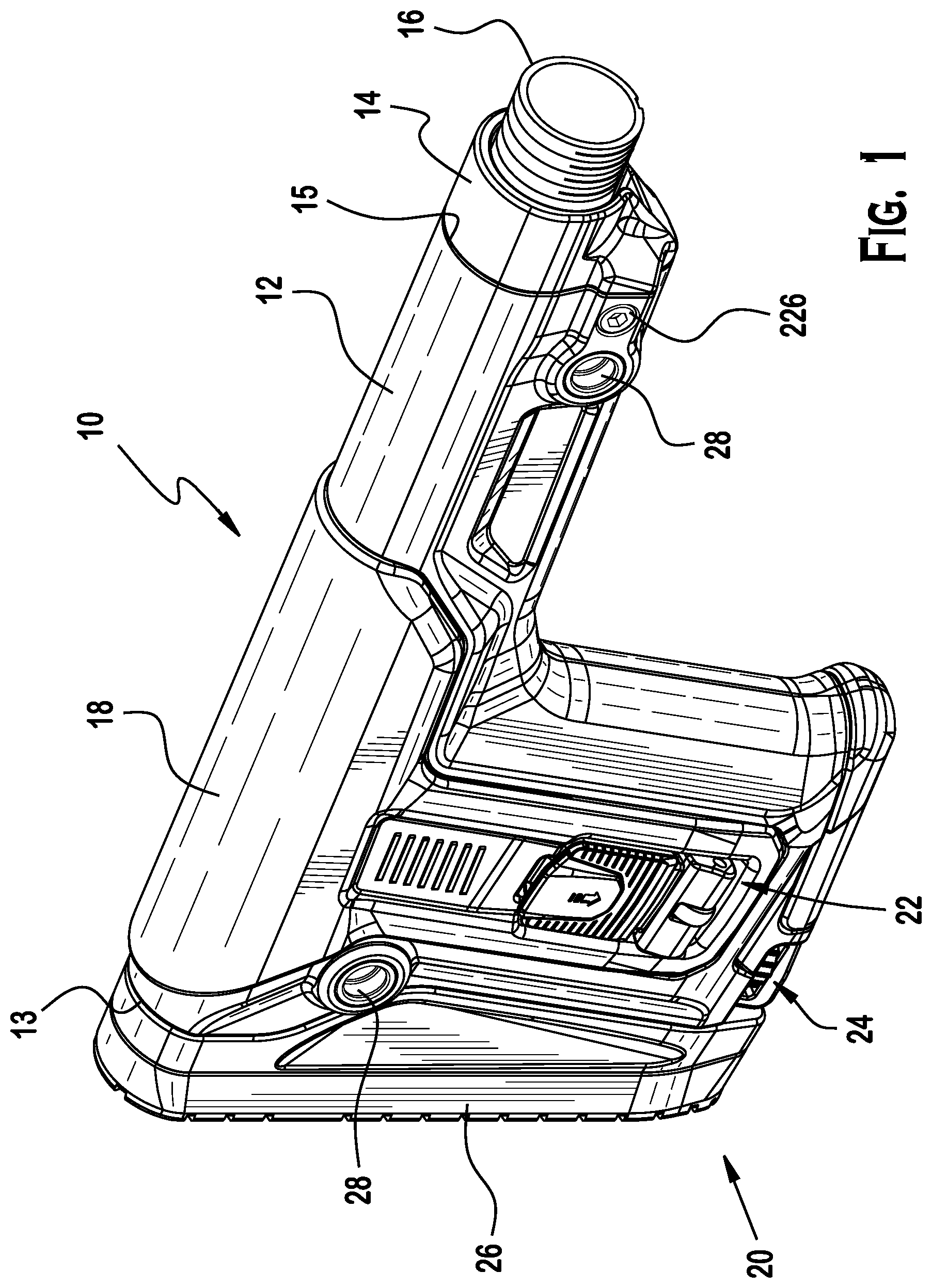
[0013] FIG. 1 is perspective view of an exemplary stock for a small arms weapon;
[0014] FIG. 2 is a rear, right, top perspective view of the stock of FIG. 1;
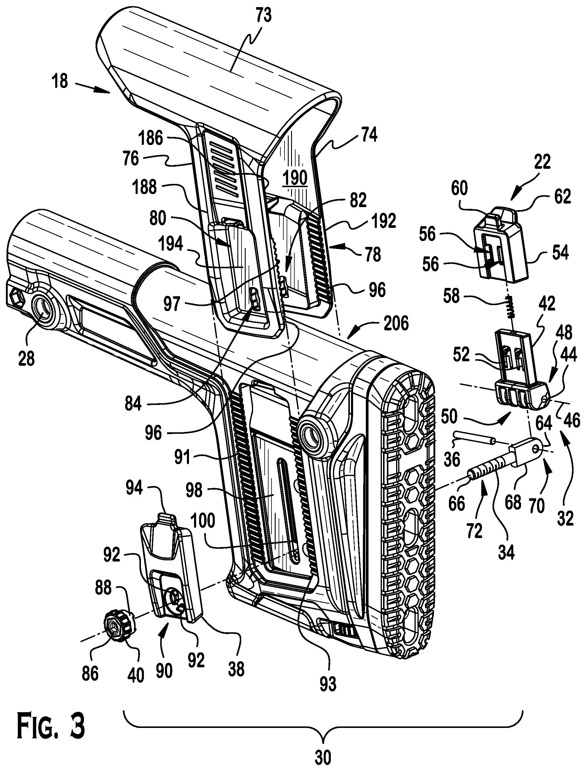
[0015] FIG. 3 is an exploded view of the cheek piece and clamp of FIG. 1;
[0016] FIG. 4 is an exploded view of the butt plate assembly of FIG. 1;
[0017] FIG. 5 is perspective view of the stock of FIG. 1 with the butt stock assembly in a collapsed position, the cheek piece in a collapsed position, and the clamp in a secured configuration;
[0018] FIG. 6 is cross-sectional view of the stock of FIG. 5 along line 6-6;
[0019] FIG. 7 is perspective view of the stock of FIG. 1 with the butt stock assembly in a fully extended position, the cheek piece in a collapsed position, and the clamp in a released configuration;
[0020] FIG. 8 is cross-sectional view of the stock of FIG. 7 along line 8-8;
[0021] FIG. 9 is perspective view of the stock of FIG. 1 with the butt stock assembly in a fully extended position, the cheek piece in a fully raised position, and the clamp in a released configuration;
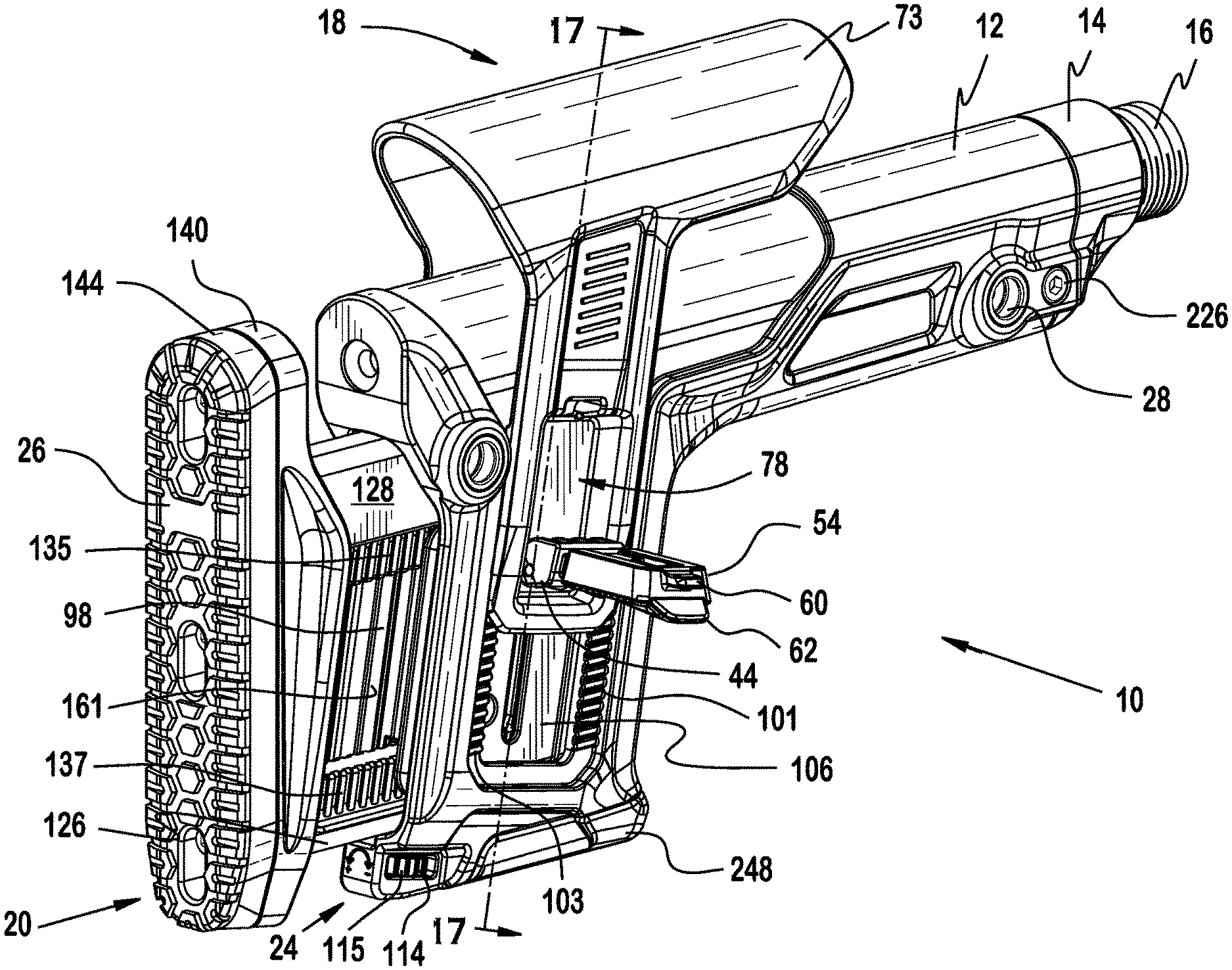
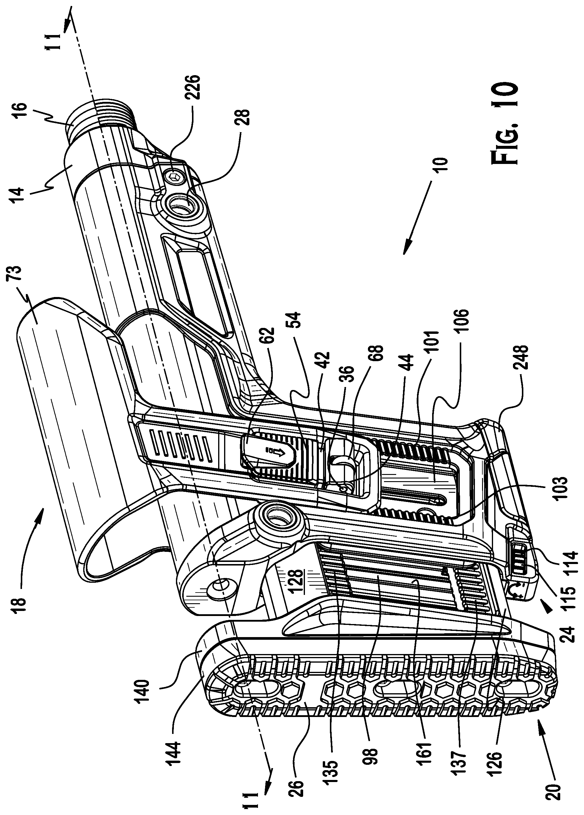
[0022] FIG. 10 is perspective view of the stock of FIG. 1 with the butt stock assembly in a fully extended position, the cheek piece in a fully raised position, and the clamp in a secured configuration;
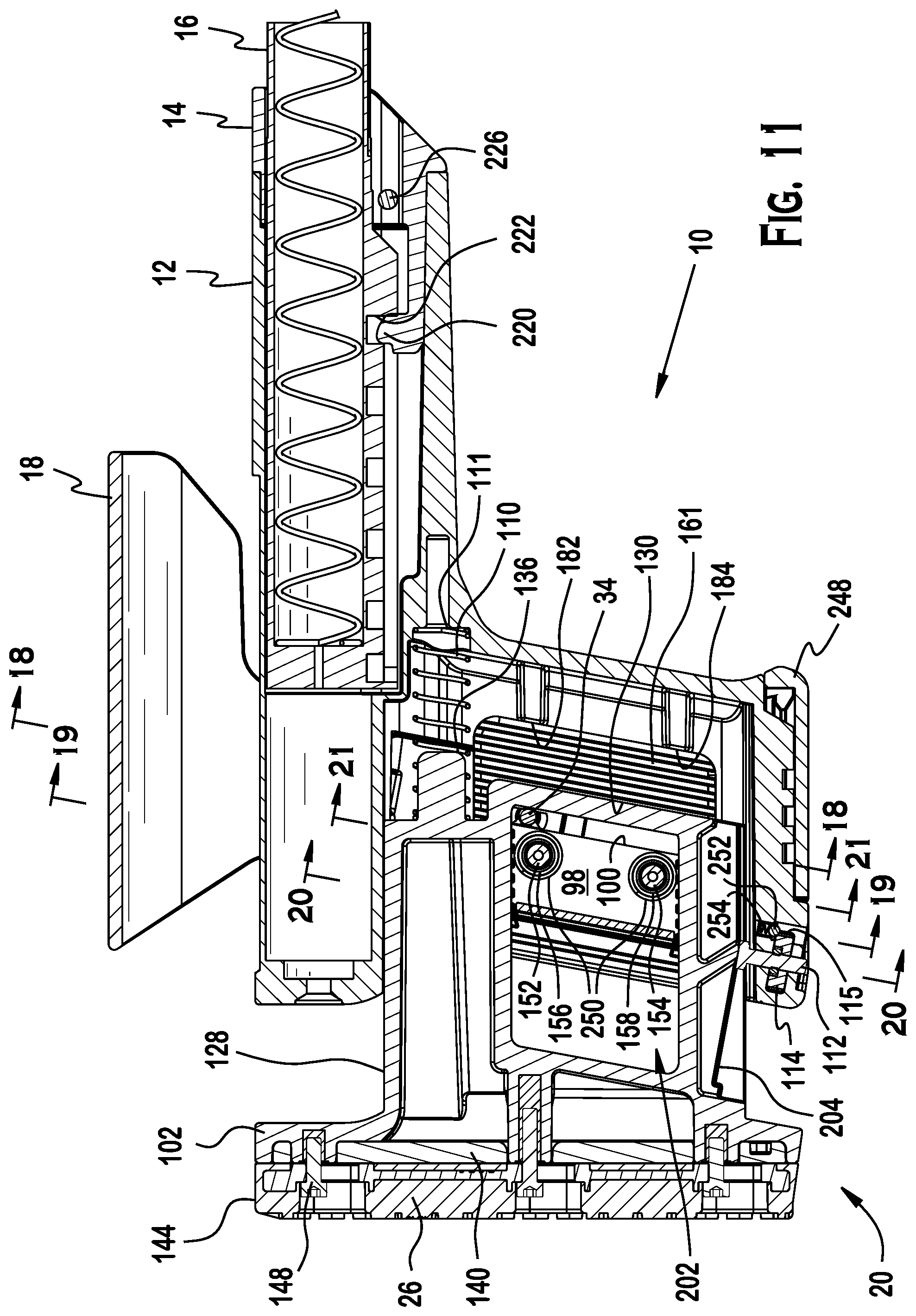
[0023] FIG. 11 is cross-sectional view of the stock of FIG. 10 along line 11-11;
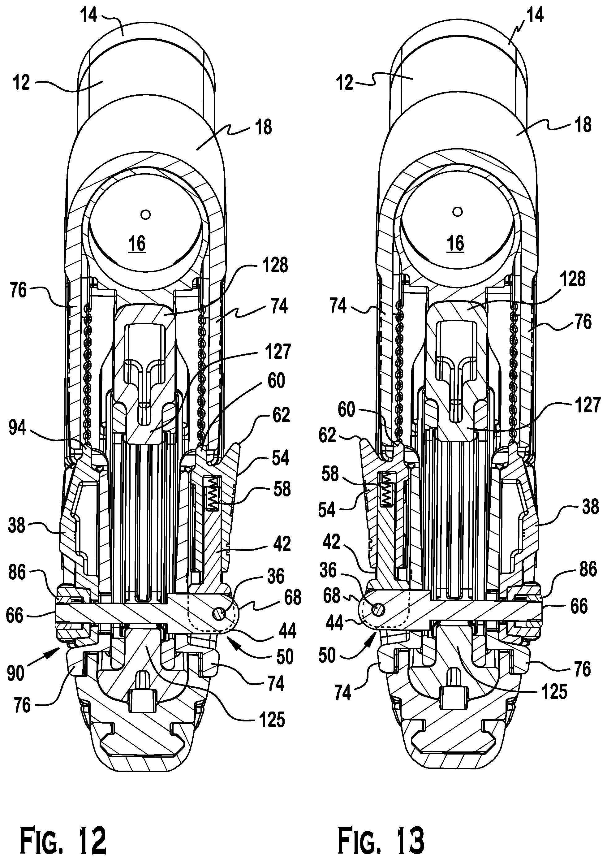
[0024] FIG. 12 is cross-sectional view of the stock of FIG. 6 along line 12-12;
[0025] FIG. 13 is a cross-sectional view of the stock of FIG. 12, the clamp being assembled for use by an operator having a left dominant hand;
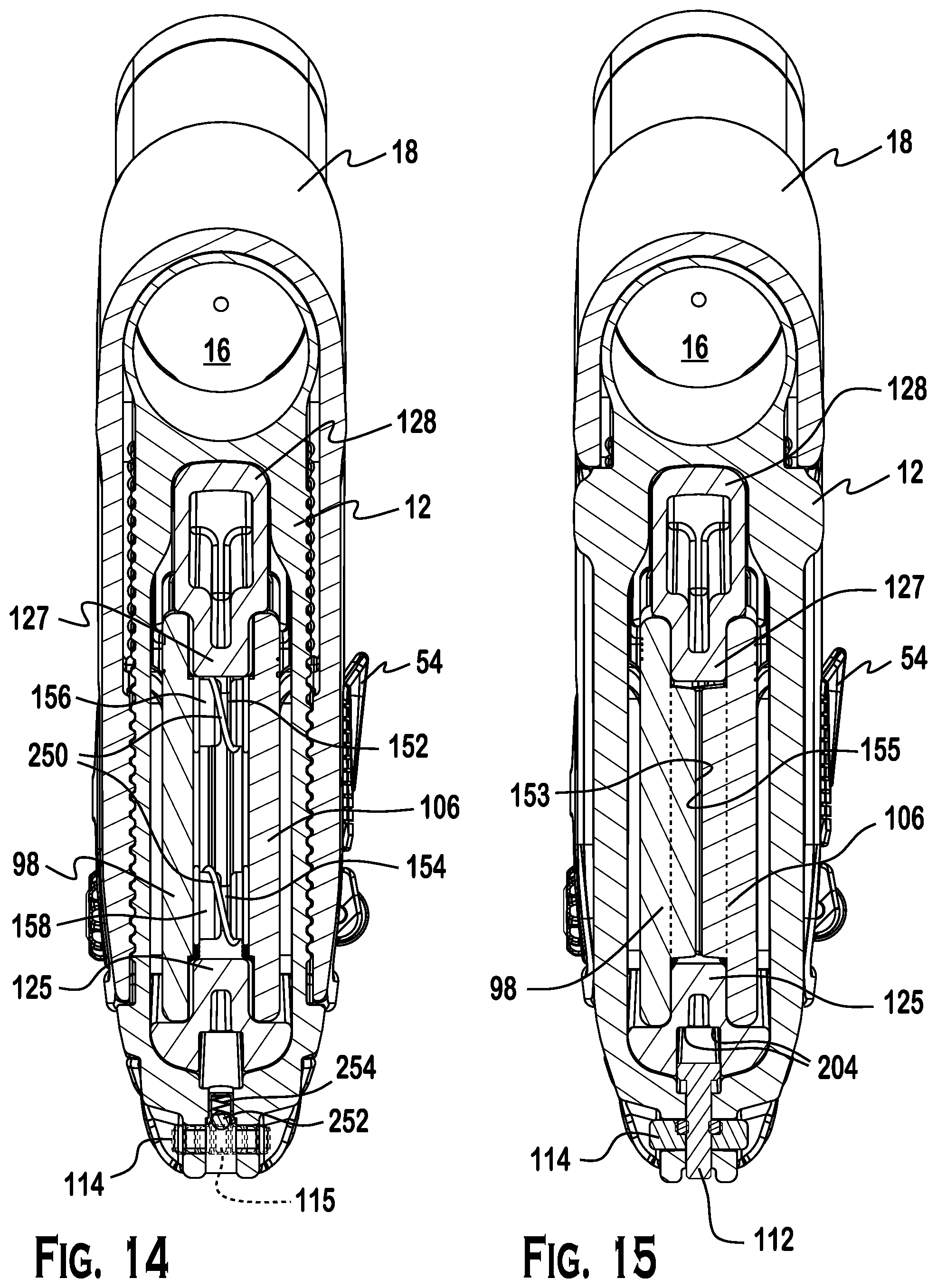
[0026] FIG. 14 is cross-sectional view of the stock of FIG. 6 along line 14-14;
[0027] FIG. 15 is cross-sectional view of the stock of FIG. 6 along line 15-15;
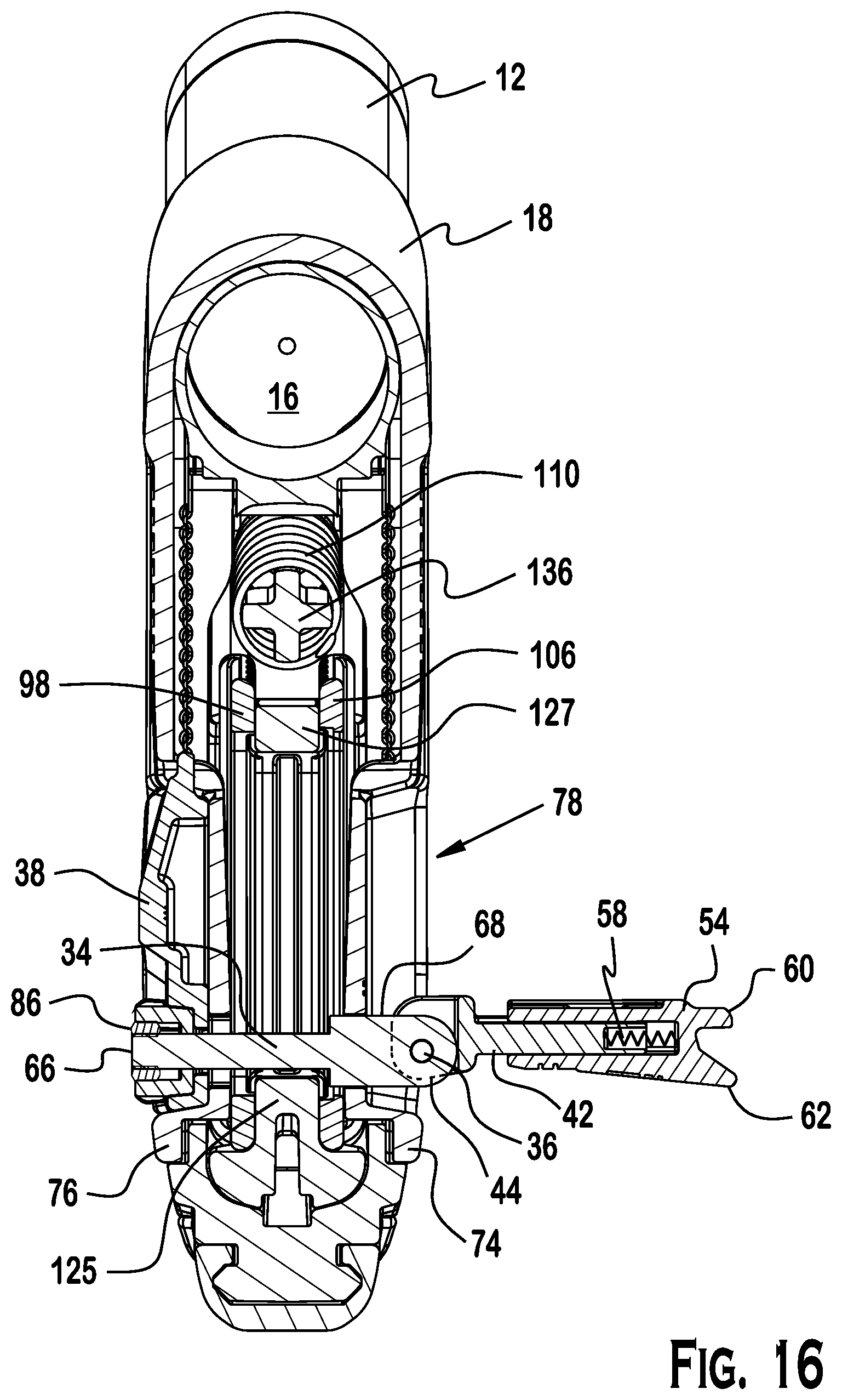
[0028] FIG. 16 is cross-sectional view of the stock of FIG. 8 along line 16-16;
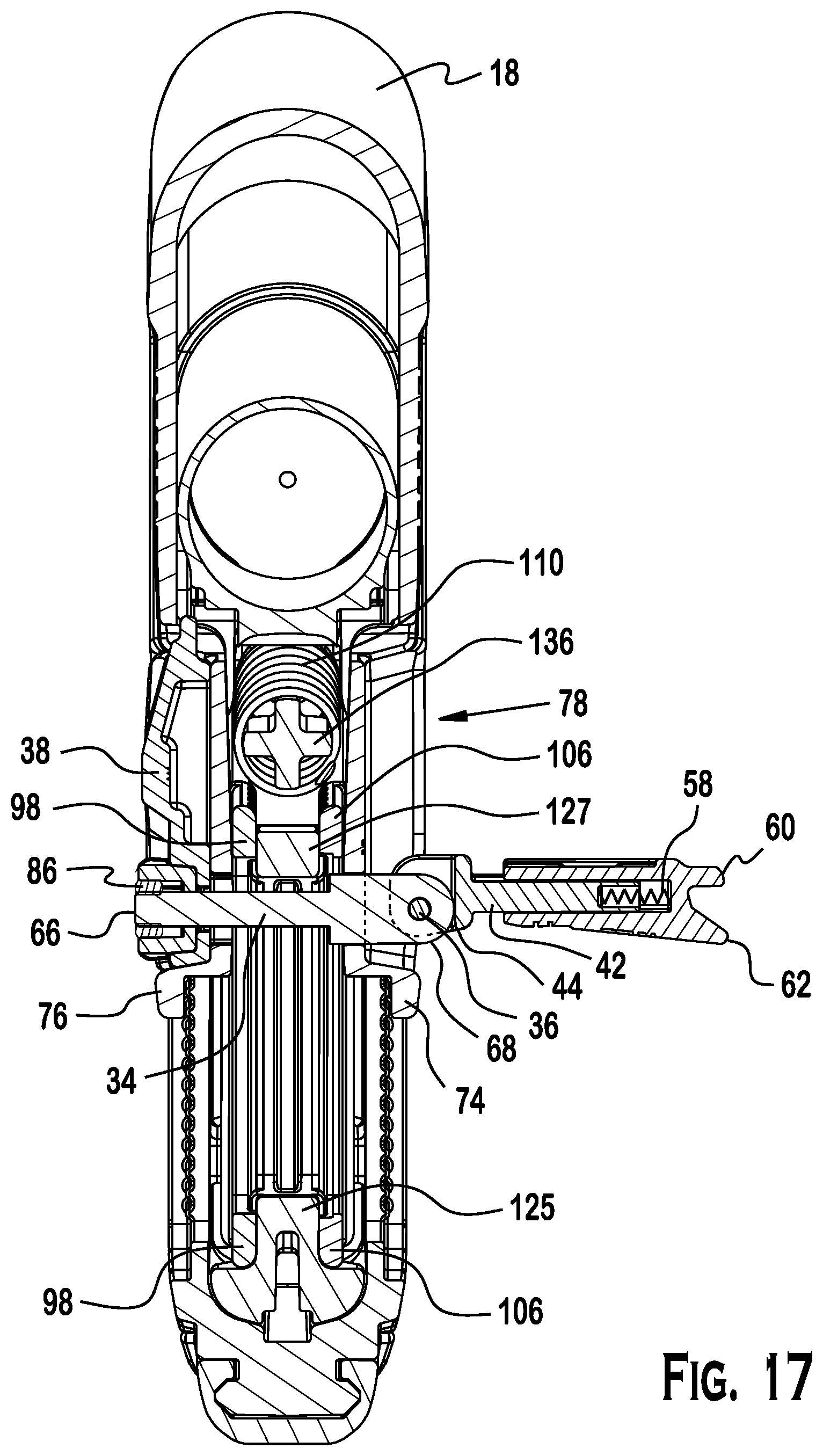
[0029] FIG. 17 is cross-sectional view of the stock of FIG. 9 along line 17-17;
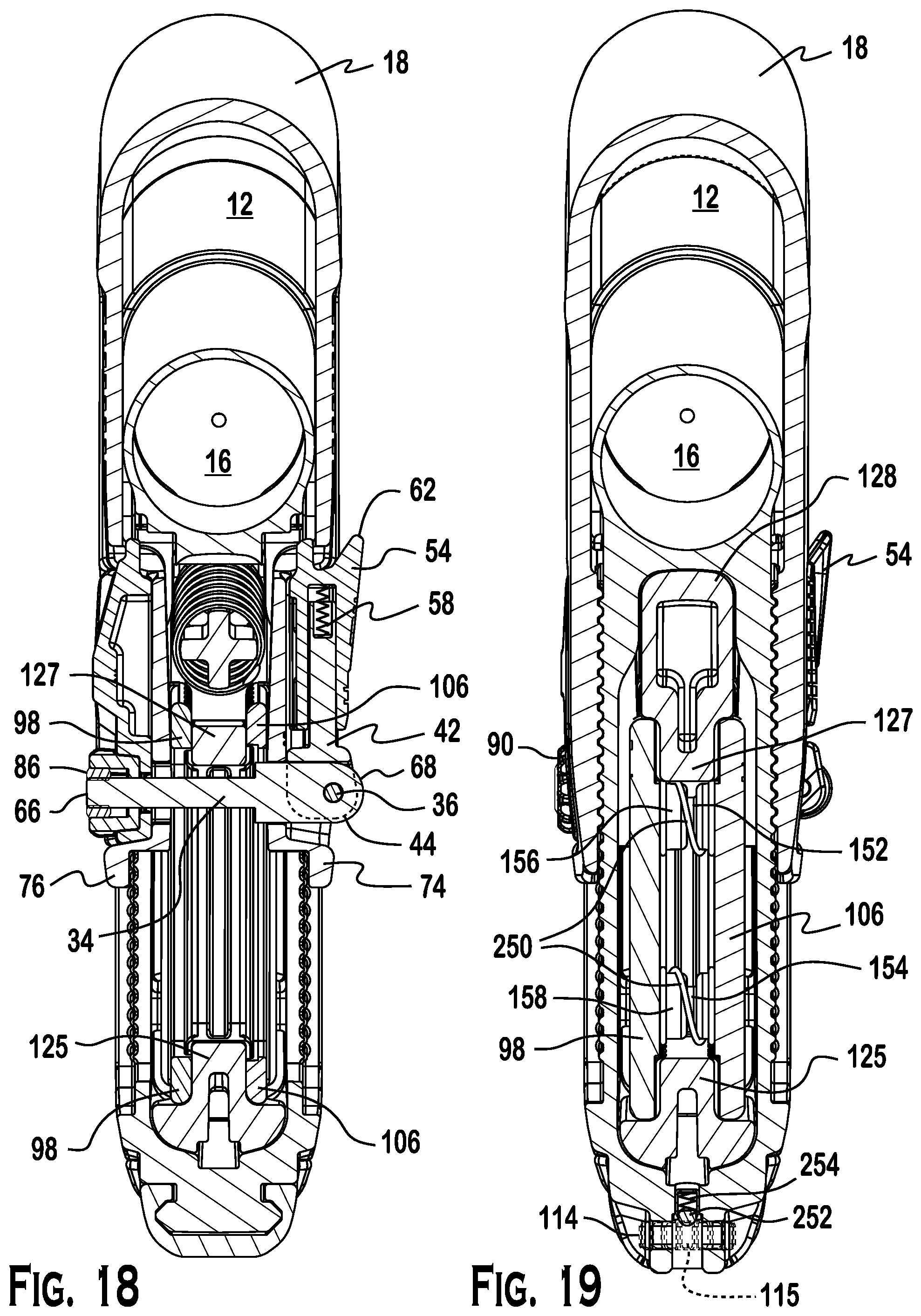
[0030] FIG. 18 is cross-sectional view of the stock of FIG. 11 along line 18-18;
[0031] FIG. 19 is cross-sectional view of the stock of FIG. 11 along line 19-19;
[0032] FIG. 20 is cross-sectional view of the stock of FIG. 11 along line 20-20;
[0033] FIG. 21 is cross-sectional view of the stock of FIG. 11 along line 21-21;
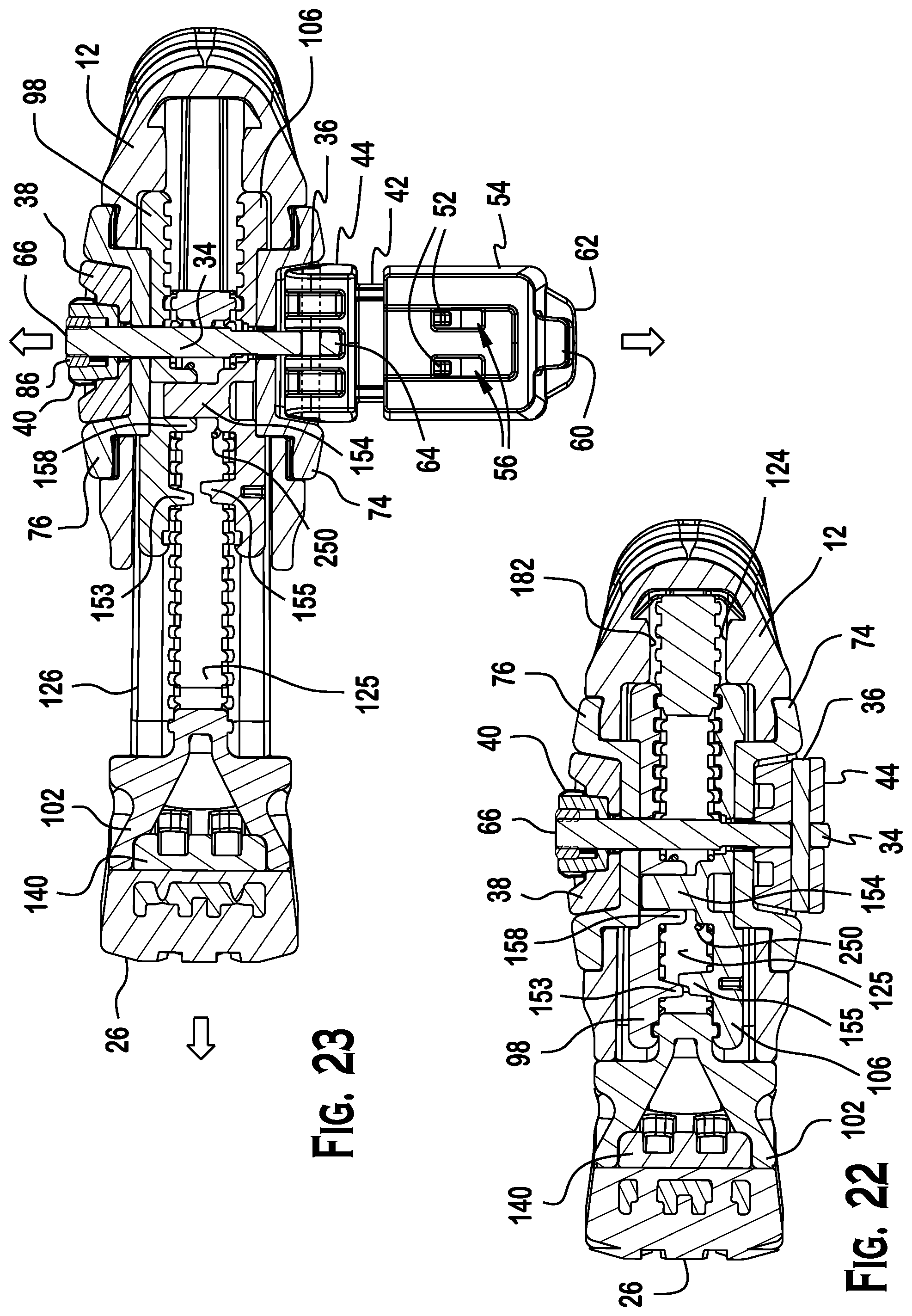
[0034] FIG. 22 is cross-sectional view of the stock of FIG. 6 along line 22-22;
[0035] FIG. 23 is cross-sectional view of the stock of FIG. 8 along line 23-23;
[0036] FIG. 24 is partial exploded view of an AR-15 firearm with a buffer tube for a collapsible butt stock and a butt stock adaptor which is configured for use with a receiver extension of a bolt action rifle;
[0037] FIG. 25 is partial perspective view of the firearm of FIG. 24 showing the butt stock adaptor fitted to the buffer tube;
[0038] FIG. 26 is partial perspective view of the firearm and butt stock adaptor of FIG. 24 showing the butt stock of FIG. 1 fitted to the butt stock adaptor and the buffer tube;
[0039] FIG. 27 is cross-sectional view of the fitted butt stock of FIG. 27 along line 27-27;
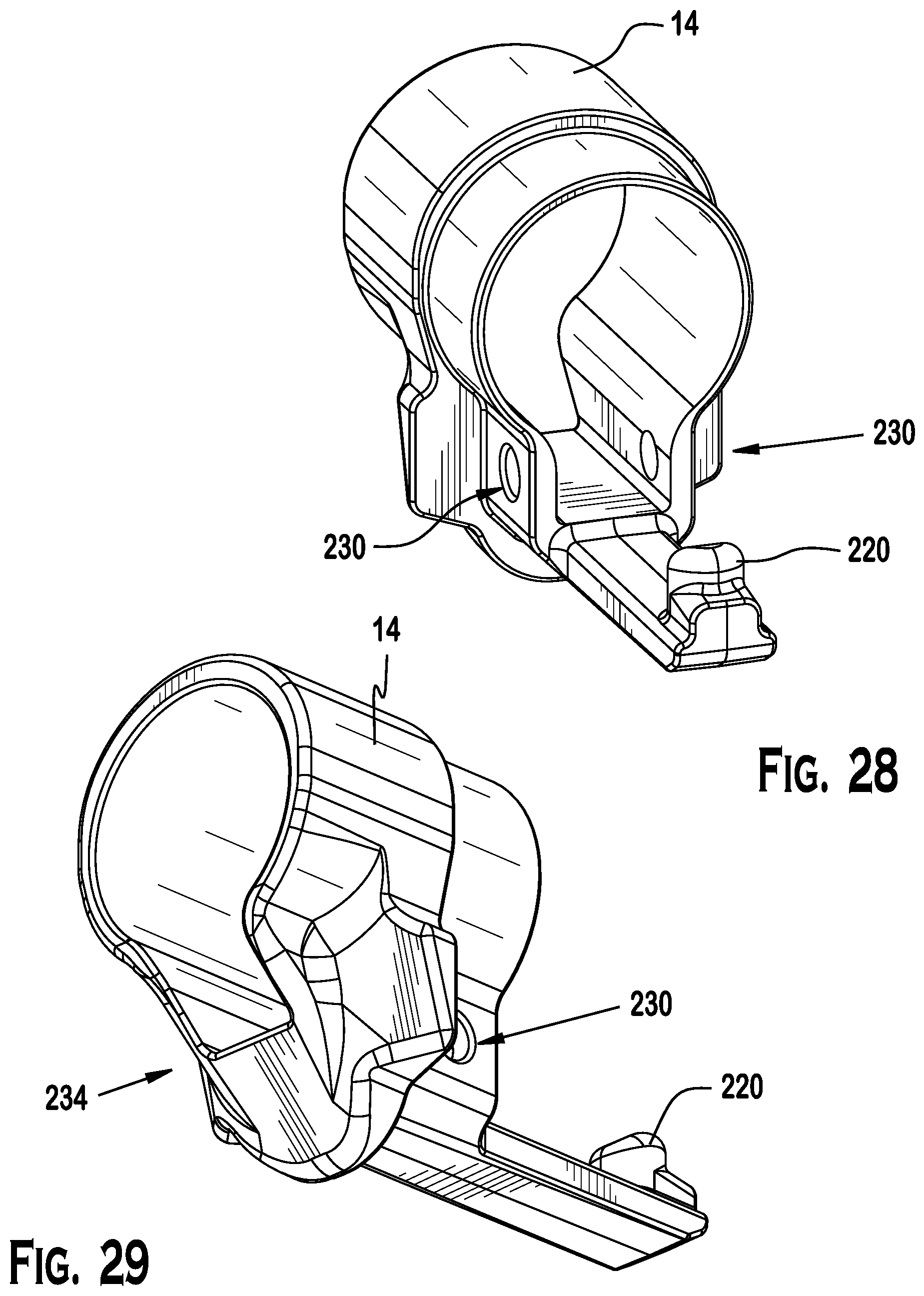
[0040] FIG. 28 is a rear, right side, top perspective view of the butt stock adaptor of FIG. 24;
[0041] FIG. 29 is a front, right side, bottom perspective view of the butt stock adaptor of FIG. 28;
[0042] FIG. 30 is a rear, right side, top perspective view of a butt stock adaptor which may be configured and dimensioned for use with a buffer tube (commercial or mil spec) and a collapsible stock for an AR-15 firearm;
[0043] FIG. 31 is a front, right side, bottom perspective view of the butt stock adaptor of FIG. 30;
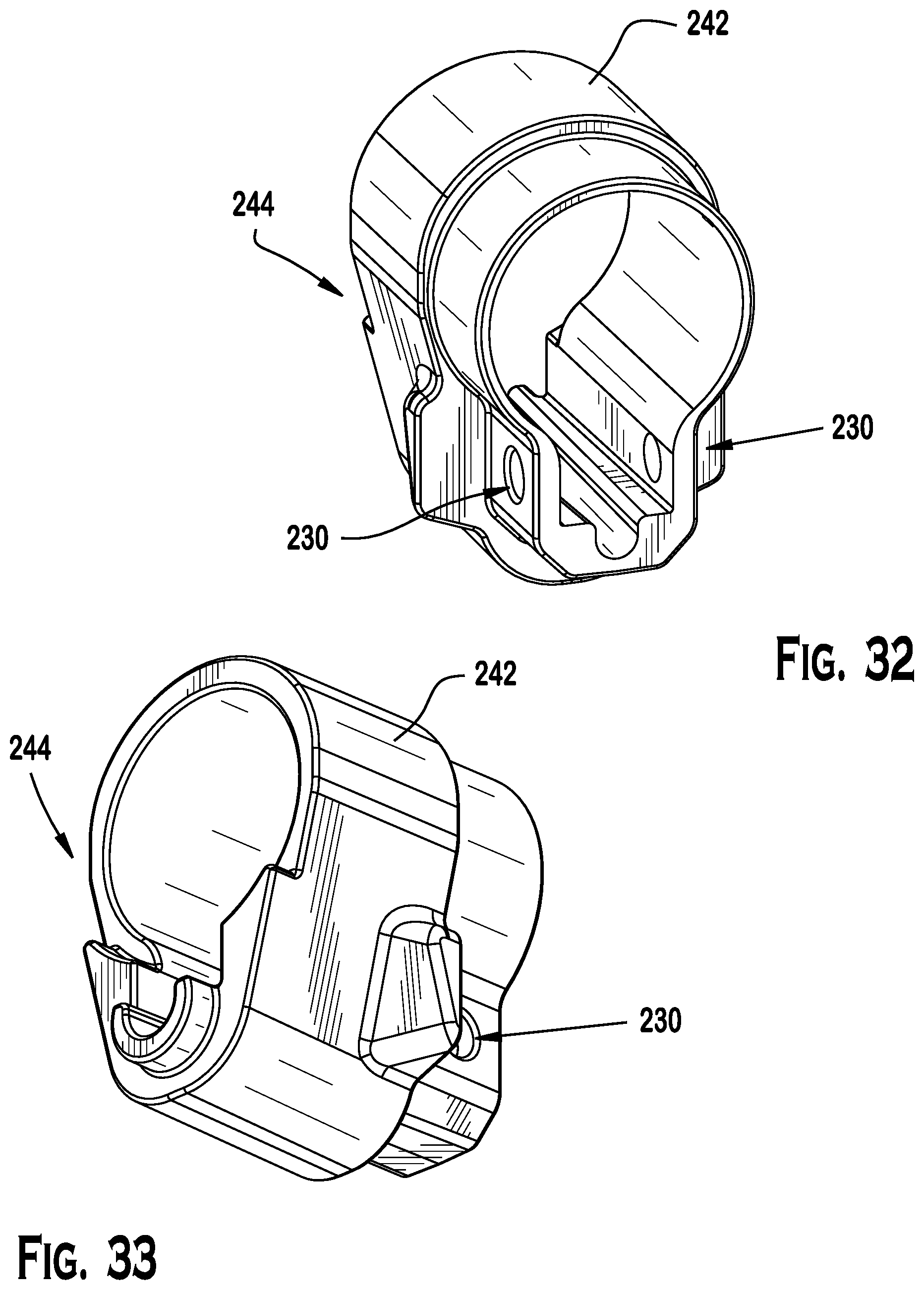
[0044] FIG. 32 is a rear, right side, top perspective view of another butt stock adaptor which is configured and dimensioned for use with a rifle length buffer tube (e.g., A2 buttstock receiver extension tube) for use with a fixed stock, including for example an AR-15 A2 or A4 firearm;
[0045] FIG. 33 is a front, right side, bottom perspective view of the butt stock adaptor of FIG. 32;
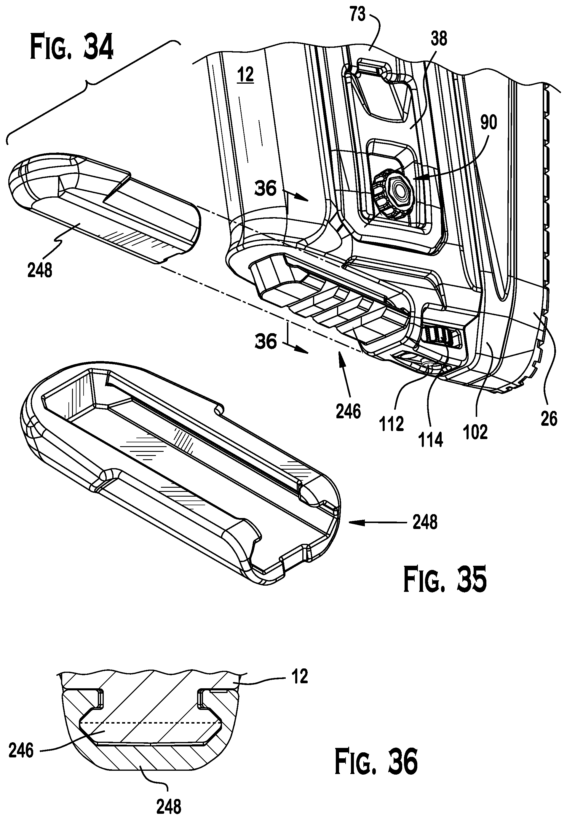
[0046] FIG. 34 is a partially exploded view of the butt stock body showing an integrally formed accessory mounting rail on the bottom of the butt stock, along with a removable cover that may be used to enclose the accessory rail when not in use.
[0047] FIG. 35 is a rear, right side, top perspective view of the removable cover of FIG. 34;
[0048] FIG. 36 is a partial sectional view of the butt stock body of FIG. 34 along line 36-36.
DESCRIPTION
[0049] FIG. 1 and FIG. 2 depict an exemplary butt stock 10 for a long arm. The butt stock 10 may include a butt stock body 12 having a proximal end 13 and a distal end 15. The butt stock may further include a cheek piece 18 and a butt plate assembly 20. The butt plate assembly 20 may include a rubber or rubberized butt pad 26. The position of the butt pad 26 may be adjustable vertically as well. The butt stock may further include a first variable adjustment regulation system 22 for selectively and independently configuring the respective positions of the butt plate assembly and the cheek piece. Moreover, the butt stock 10 may include a second variable adjustment regulation assembly 24 for regulating displacement of the butt plate assembly. The butt stock body 12 further may include a quick disconnect mount (QD mount) near the proximal end 13, as well as a QD mount near the distal end 15. Additionally, the butt stock body 12 may be of a modular design which may connect with an adaptor 14 for a specific firearm type or manufacture. The adaptor 14 may be secured to the distal end 15 of the butt stock body 12, as well as to a receiver extension 16 of a firearm.
[0050] Referring to FIG. 4, the butt stock body 12 may include a butt plate receptacle 108. The butt plate receptacle 108 may be situated adjacent to the proximal end 13 of the butt stock body 12. For example, the butt plate receptacle 108 may be housed in the butt stock body 12 and may extend from the proximal end 13 toward the distal end 15. The butt plate receptacle 108 may include a port side sidewall 178 and a starboard side sidewall 180. Additionally, the butt plate receptacle 108 may include a lower rail receiving track 120 between the port side sidewall 178 and the starboard side sidewall 180. The butt plate receptacle further may include a starboard side upper stop 122, a starboard side lower stop 124, and a starboard side opening 118.
[0051] As shown in FIG. 6, the butt plate receptacle 108 further may include a port side upper stop 182, a port side lower stop 184, and a port side opening 118. Moreover, the butt stock body 12 may include a butt plate travel adjustment mechanism 113 which interacts with the frame 108 to selectively regulate rearward travel of the butt plate assembly 20. lower rail receiving track 120. For example, the butt plate travel adjustment mechanism 113 may include a screw 112 and an adjustment knob 114 adjacent to the lower rail receiving track 120. More particularly, the adjustment knob 114 may be disposed at an angle with respect to the lower rail receiving track 120 and connected to the screw 112 by a mating screw thread. Rotation of the adjustment knob 114 in one direction may advance the screw into the lower rail receiving track 120 and counter rotation of the adjustment knob may retract the screw.
[0052] Referring to FIG. 3, the butt stock body 12 further may include a cheek piece shaped recess 206 which is configured and dimensioned to receive the cheek piece 18. Additionally, the butt stock body may include a port side opening 116 and a starboard side opening 118. See e.g., FIG. 4. The port side opening 116 may extend from the port sidewall 178 of the butt plate receptacle 108 to the port side of the cheek piece recess 206. The port side of the cheek piece recess 206 further may include proximal and distal horizontally fluted tracks 91, 93. Similarly, the starboard side opening 118 may extend from the starboard sidewall 180 of the butt plate receptacle 108 to the starboard side of the cheek piece recess 206. Also, the starboard side of the cheek piece recess 206 may include proximal and distal horizontally fluted tracks 101, 103. See e.g., FIG. 10.
[0053] Referring to FIG. 1 and FIG. 2, the butt stock body 12 further may include a quick disconnect mount (QD mount) near the proximal end 13, as well as a QD mount near the distal end 15. Moreover, the butt stock may be a modular design that includes an adaptor 14 for a specific firearm type or manufacture. The adaptor 14 may be secured to the distal end 15 of the butt stock body 12, as well as to a receiver extension 16 of a firearm.
[0054] Referring to FIG. 4, the butt plate assembly 20 may include a butt plate 102, a frame 104, a port side clamping plate 98, a starboard side clamping plate 106, and an axially oriented compression spring 110. The butt pad 26 may be positioned against a cover plate 140 and secured to the butt plate. For example, the butt plate may include one or more cylindrical projections 144 which possess a side wall 138 that is configured and dimensioned to serve as a mount for a mating hole 142 in the cover plate 140. The one or more of the cylindrical projections 138 further may include a threaded bore 150. The one or more threaded bores 150 may be configured and dimensioned to releasably mate with a corresponding socket head screw 148 or another suitable fastener. Additionally, the butt plate assembly 20 further may include one or more transversely oriented compression springs (not shown) which may be positioned between the port side clamping plate 98 and the starboard side clamping plate 106. For example, one transversely oriented compression spring may be mounted on an upper transverse member 152 located on the starboard side clamping plate 106. Similarly, another transversely oriented compression spring may be mounted on a lower transverse member 154 located on the starboard side clamping plate 106.
[0055] The butt plate 102 may be secured to or integrally formed with the frame 104. The frame 104 may include an upper rail 127 and a lower rail 125. A front rail 130 may connect the upper rail 127 to the lower rail 125 near the distal end of the frame. The upper rail 127 further may include a port side fluted upper rail face 134 and a starboard side fluted upper rail face 135 (see e.g., FIG. 7). Similarly, the lower rail 125 may include a port side fluted lower rail face 132 and a starboard side fluted lower rail face 137 (see e.g., FIG. 7). The lower rail may include a base 126. The upper rail further may include a comb 128. Referring to FIG. 16, a spring guide 136 may projects axially away from the comb. As shown in FIG. 4, the frame 104 may further include a passage 202 located between the upper rail 127 and the lower rail 125. Further, the passage 202 may be located between the butt plate 102 and the front rail 105. The passage 202 may have rectangular shape.
[0056] The port side clamping plate 98 and the starboard side clamping plate 106 may each include an elongated slot 100, 164. Further, the port side clamping plate 98 and the starboard side clamping plate 106 may each include an interior oriented face 99, 168 and an exterior oriented face 101, 166. The respective interior oriented faces 99, 168 may include a clamp face having a plurality of grooves 161, 162. The plurality of grooves 161, 162 may be in parallel alignment. Further, the plurality of grooves 161, 162 may be in parallel alignment with the elongated slots 100, 164. The respective interior oriented faces 99, 168 may each further include a spacer 153, 155. Additionally, the exterior oriented faces 101, 166 may include a recess 170, 172 and the elongated slots 100, 164 may each intersect the base of the recess 170, 172. Moreover, the port side clamping plate 98 may include an upper transverse member receiving hole 156 and a lower transverse member receiving hole 158.
[0057] The port side clamping plate 106 and the starboard side clamping plate may be juxtaposed, and the frame 104 may be positioned between them. The interior oriented faces 99, 168 may be positioned opposite the upper rail 127 and a lower rail 125 of the frame. The elongated slots 100, 164 may be aligned. The upper transverse member 152 and the lower transverse member 154 may be positioned in the passage 202 and received respectively by the upper transverse member receiving hole 156 and the lower transverse member receiving hole 158. A transversely oriented compression spring may be mounted on the upper transverse member 152 and/or lower transverse member 154 to bias the port side clamping plate 106 and the starboard side clamping plate away from the frame. Preferably, however, one transversely oriented compression spring may be mounted on the upper transverse member 152 and another transversely oriented compression spring may be mounted on the lower transverse member 154 to bias the port side clamping plate 106 and the starboard side clamping plate away from the frame. Nevertheless, a transversely oriented compression spring may not be included. For example, a transversely oriented compression spring may not be necessary where the cheek piece is formed from a resilient material such that the cheek rest risers are constructed to be biased outwardly. In another example, a transversely oriented compression spring may not be desirable in order to enhance tactile feedback to an operator when adjusting trigger pull length. Generally, however, the port side fluted upper and lower rail faces 132, 134 may be positioned opposite the plurality of grooves 161 located on the port side clamping plate, and the starboard side fluted upper and lower rail faces 135, 137 may be positioned opposite the plurality of grooves 162 located on the starboard side clamping plate 106.
[0058] The frame 104 may be slidably received in the butt plate receptacle 108. Referring to FIG. 6, the front rail 120 of the frame may be set against the port side upper stop 182 and port side lower stop 184--as well as the starboard side upper stop 122 and starboard side lower stop 124--when the butt stock assembly is in the collapsed position. By contrast, the screw 112 of the butt plate travel adjustment mechanism 113 may contact a lower surface 208 of the frame to block movement of the frame axially in the proximal direction of the butt stock body 12. See e.g., FIG. 8. For example, the lower surface may be disposed and an acute angle with respect to the screw 112 and lower rail receiving track 120 such that movement of the frame axially in the proximal direction of the butt stock body 12 is progressively limited as the screw is advanced toward the lower surface 204. Moreover, as shown in FIG. 6 and FIG. 8, the spring 110 may be compressed between the comb 128 and end wall 111 of the butt plate receptacle 108 to spring load the frame 104.
[0059] Referring to FIG. 3, the cheek piece 18 may include a cheek rest 73, a port side cheek rest riser 76 connected to the cheek rest, and a starboard side cheek rest riser 74 connected to the cheek rest. The port side cheek rest riser 76 may include a first inner surface 186 facing the starboard side cheek rest riser 74, a first outer surface 188 facing away from the starboard side cheek rest riser 74, and a port side clamp receptacle 80 extending from the first outer surface 188 to a first end wall 194 located between the first inner surface 186 and the first outer surface 188. The first end wall 194 may further include a first aperture 84 which extends from the first end wall 194 to the first inner surface 186. Similarly, the starboard side cheek rest riser 74 may include a second inner surface 190 facing the starboard side cheek rest riser 74, a second outer surface 192 facing away from the starboard side cheek rest riser 74, and a starboard side clamp receptacle 78. The starboard side clamp receptacle 78 may extend from the outer surface 192 to a second end wall 196 located between the second inner surface 190 and the second outer surface 192. The second end wall 196 may include a second aperture which extends from the second end wall 196 to second inner surface 190. Moreover, the first inner surface 186 of the port side cheek rest riser 76 may include a horizontally fluted track 97, and the second inner surface 190 of the starboard side cheek rest riser 74 may include a horizontally fluted track 96.
[0060] The butt stock 10 may further include a clamp 30. The clamp 30 may include an eccentric lever 32, a locking rod 34, and an anchor 38. Referring to FIG. 12, the butt stock 10 may be assembled with the eccentric lever 32 positioned in the starboard side clamp receptacle 78 and the anchor positioned in the port side clamp receptacle 80. In this configuration, the butt stock 10 may be adapted for use by an operator having a dominant right hand (e.g., a right handed shooter). By contrast, in FIG. 13, the butt stock 10 may be assembled with the eccentric lever 32 positioned in the port side clamp receptacle 80 and the anchor positioned in the starboard side clamp receptacle 78. In this configuration, the butt stock 10 may be adapted for use by an operator having a dominant left hand (e.g., a left handed shooter).
[0061] In FIG. 3, the eccentric lever 32 may include an eccentric portion 44 including a third longitudinal axis 46. Further, the eccentric portion may include a bore 48 extending along the third longitudinal axis 46, and a locking rod receptacle 50 which intersects the bore 48. The eccentric portion further may include a lever arm 42 connected to the eccentric portion 44. The lever arm 42 may include a plurality of resilient hooks 52. Moreover, the eccentric portion may include a latch housing 54. The latch housing 54 may be disposed over the lever arm 42. The latch housing further may include a plurality of rectangular openings which are configured and dimensioned to form a sliding press fit connection with the plurality of resilient hooks 52. The latch housing 54 may include a latch 60, and a tab 62 offset from the latch. A compression spring 58 further may be positioned between the lever arm 42 and the latch housing 54. The compression spring 58 may bias the latch housing 54 away from the lever arm 42. Additionally, the locking rod may include a proximal end 64 and a distal end 66. The proximal end 64 of the locking rod may include a head 68. The head 68 may include a through hole 70. The distal end of the locking rod may be opposite to the proximal end 64. The locking rod 34 may further include a screw thread 72 adjacent to the distal end 66. The anchor may include a nut receiving receptacle 90, a locking rod receiving bore 198, and a flange 94. Also, the clamp may further include pin 36 and a nut 40. The nut may include a threaded bore 200. The head 68 of the locking rod 34 may be disposed in the locking rod receptacle 50, and the pin 36 may be positioned in the bore 48 of the eccentric portion 44 and the through hole 70 in the head 68 of the locking rod 34. Further, the nut 40 may be positioned in the nut receiving receptacle 90 of the anchor, and the screw thread 72 adjacent the distal end of the locking rod 34 may be mated with the screw thread 200 of the nut 40.
[0062] Referring to FIG. 7 and FIG. 9, the clamp 30 may be used to position the port side cheek rest riser 76 and the starboard side cheek rest riser 74 with respect to the butt stock body 12. Referring to FIG. 5 and FIG. 10, by contrast, the clamp 30 may be used to secure the position of the cheek piece 18 with respect to the butt stock body 12. Further still, the clamp 30 may be used to secure the port side clamping plate 98 and the starboard side clamping plate 106 with respect to the frame 104, and thus the clamp 30 may be used to selectively position the cheek piece 18, as well as selectively fix the position of the cheek piece and the butt plate assembly 20.
[0063] For example, as shown in FIG. 5 and FIG. 12, the lever arm 42 and latch housing 54 may be folded upward such that the eccentric portion 44 is positioned to shorten the clamp 30 and fix the position of the cheek piece 18 with respect to the butt stock body 12, as well as to secure the port side clamping plate 98 and the starboard side clamping plate 106 with respect to the frame 104. See also, FIG. 6, FIG. 14, FIG. 15 and FIG. 21. Moreover, the lever arm 42 and latch housing 54 may be positioned in the starboard side clamp receptacle 78. See e.g., FIG. 12. Furthermore, the latch 60 may be spring biased into a catch 208 (or slot) in the clamp receptacle. Id. The latch 60 may be uncoupled from the catch 208 by depressing the tab 72 of the latch housing. The lever arm and latch housing may then be rotated away from clamp receptacle. See e.g., FIG. 7. Rotation of the lever arm 42 and latch housing 54 away from the clamp receptacle may lengthen the clamp 30 and unfix (or unlock) the position of the cheek piece 18 with respect to the butt stock body 12, as well as to unfix (or unlock) the port side clamping plate 98 and the starboard side clamping plate 106 with respect to the frame 104. See e.g., FIG. 8, FIG. 16 and FIG. 23. Referring to FIG. 9, FIG. 17, FIG. 22, and FIG. 23 in such an unfixed (or unlocked) configuration, an operator may move the lever arm and latch housing to selectively position the cheek piece. Independently, the operator may allow the compression spring 110 to reposition the butt stock assembly. See e.g., FIG. 7 and FIG. 8. Accordingly, the position of the cheek piece 14 may be adjusted by the non-dominant hand of the operator while the dominant hand of the operator holds the firearm grip and obtains a preferred shooting position. See e.g., FIG. 17. In this regard, the position of the butt stock assembly may be adjusted against the spring force applied by the compression spring 110 by applying counter force(s) to the butt plate with the shoulder connected to the operator's dominant hand. Referring to FIG. 10, FIG. 11, FIG. 18 and FIG. 20 upon completion of such a variable adjustment to the position of the cheek piece 18 and butt stock assembly 20, the operator may then fold the lever arm and latch housing up and into the clamp receptacle to fix or lock the selected position of the cheek piece 18 with respect to the butt stock body 12, as well as to fix (or lock) the port side clamping plate 98 and the starboard side clamping plate 106 with respect to the frame 104, and thus achieve a preferred shooting configuration. See also, FIG. 19 and FIG. 21.
[0064] Referring to FIG. 24 and FIG. 25, an adaptor 14 may be fitted on to a buffer tube 16 (or receiver extension) of a firearm 224. Optionally, a hook 220 on the adaptor may be placed into a stock stop position 222 on the underside of the buffer tube 16 (or receiver extension). As shown in FIG. 26 and FIG. 27, the butt stock body 12 may be fitted over the adaptor 14 and buffer tube (or receiver extension) and secured by a socket head screw 226. The socket head screw 226 may be positioned in a hole 228 near the distal end of the modular stock body 12. Referring to FIG. 27, the socket head screw 226 may pass through a hole 230 in the adaptor 14 and then be received in a captured nut 232 on the opposite side of the modular butt stock body 12. FIG. 28 and FIG. 29 show a first adaptor 14 with a tapered distal end 234 and a proximal hook 220. The first adaptor 14 may be configured and dimensioned for use with a receiver extension of a bolt action rifle. Although the tapered distal end 234 may be configured and dimensioned to provide additional clearance around the grip of a bolt action rifle, the tapered distal end 234 be modified for other firearm types or manufacture.
[0065] FIG. 30 and FIG. 31 show a second adaptor 236 with a stepped distal end 238 and a proximal hook 240. The second adaptor 236 may be configured and dimensioned for use with an AR-15 buffer tube (commercial or mil spec) that is designed for use with a collapsible stock.
[0066] FIG. 32 and FIG. 33 show a third adaptor 242 with a stepped distal end 244 but without a proximal hook. The third adaptor 242 may be configured and dimensioned for use with a rifle length buffer tube (e.g., A2 standard AR-15 buffer tube) for use with an AR-15 rifle. In use, the third adaptor may be fitted to the distal end of the buffer tube, and the proximal end of the buffer tube may be positioned in the butt stock body until the proximal end abuts the receiver extension tube cavity end wall. A screw further may be advanced through a fastener hole adjacent the butt plate 102 and into the buffer tube to secure the buffer tube body in the cavity. Additionally, a socket head screw may be advanced through the through holes 230 to secure the adaptor to the buffer tube. In alternate embodiments, the first two adaptors also may be respectively implemented without a proximal hook.
[0067] FIG. 34 shows an integrally formed picatinny rail 246 formed on the bottom of the butt stock body 12. A rail cover 248 may be positioned over the picatinny rail 246. FIG. 35 shows a perspective view of the rail cover 248. FIG. 36 shows a cross-sectional view of the rail cover 248 mounted on the picatinny rail 246. The picatinny rail 246 may be used to mount a tactical accessory to the butt stock body. Generally, the butt stock body and other components of the butt stock may be constructed from one or more of the following materials, as appropriate and without limitation, metal, metal alloys, wood, plastic, polymer materials, reinforced polymer materials, thermoplastic materials, and combinations thereof.
[0068] In view of the above, an exemplary modular stock 10 and associated exemplary adaptors (14, 236, 242) for use with a specific firearm or receiver extension are disclosed (see e.g. FIG. 1, FIG. 2, FIG. 28, FIG. 30 and FIG. 32). In one embodiment, the stock 10 may include a butt stock body 12. The butt stock body 12 may include a first longitudinal axis. The butt stock body 12 further may include a proximal end 13 and a distal end 15 spaced from the proximal end along the first longitudinal axis. As shown in FIG. 4, the butt stock body 12 further may include a butt plate receptacle 108 situated adjacent to the proximal end 13. Also, the modular stock 10 may include a butt plate assembly 20 positioned in the butt plate receptacle 108. Referring to FIG. 3 and FIG. 4, a cheek piece 18 may be secured to the butt stock body 12 and the butt plate assembly 20. Further, the butt stock body 12 may include a clamp 30. The clamp 30 may include first and second configurations such that in the first configuration (e.g., FIG. 9) the clamp permits independent movement of the butt plate assembly 20 and the cheek piece 18 relative to the butt stock body 12, and such that in the second configuration (e.g., FIG. 10) the clamp fixes movement of the butt plate assembly 20 and the cheek piece relative to the butt stock body. Also, in the second configuration, the cheek piece may be clamped against the butt stock body 12 and the butt plate assembly 20.
[0069] Referring to FIG. 4, the butt plate receptacle 108 may be housed in the butt stock body 12. The butt plate receptacle may extend from the proximal end 15 of the butt stock body 12 toward the distal end 13 of the butt stock body 12. The butt plate receptacle 108 may include a port side butt plate receptacle sidewall 178, a starboard side butt plate receptacle sidewall 180, and a lower rail receiving track 120 disposed between the port side butt plate receptacle sidewall 178 and the starboard side butt plate receptacle sidewall 180. Additionally, the port side butt plate receptacle sidewall 178 may include a port side upper stop 182, a port side lower stop 184, and a port side opening 116. Further, the starboard side butt plate receptacle sidewall 180 includes a starboard side upper stop 122, a starboard side lower stop 124, and a starboard side opening 118. Referring to FIG. 6, FIG. 8, FIG. 14 and FIG. 15, the butt plate receptacle 108 further may include a butt plate travel adjustment mechanism 113. The butt plate travel adjustment mechanism 113 may include a screw 112 and an adjustment knob 114. The adjustment knob 114 may include peripheral recesses that improve the ability of a user to grip and manipulate the adjustment knob. Also, the butt plate adjustment mechanism may include an indexing member 252 which may be biased by a spring 254 against the adjustment knob. Further, the indexing member may be seated against one of the peripheral recesses to secure the relative position of the adjustment knob 114 and screw 112. Preferably, the indexing member may be a ball bearing. Further still, the adjustment knob 114 may be disposed at an acute angle with respect to the lower rail receiving track 120 and connected to the screw by a mating screw thread. For example, the acute angle may range from about 5 degrees to about 60 degrees measured from the horizontal plane upon which the frame 104 translates. More preferably, the acute angle may range from about 8 to about 12. Most preferably, the acute angle may be about 10.5 degrees. Generally, rotation of the adjustment knob in a first direction may advance the screw into the lower rail receiving track 120 to restrict rearward travel of the butt plate assembly 20. By contrast, rotation of the adjustment knob in an opposite direction may withdraw the screw from the lower rail receiving track 120 to increase rearward travel of the butt plate assembly 20. Accordingly, the butt plate travel adjustment mechanism 113 may be used to selectively regulate rearward travel of the butt plate assembly 20.
[0070] Referring to FIG. 1 and FIG. 2, the butt stock body 12 may include a quick disconnect mount 28 disposed between the cheek piece 18 and the distal end 13 of the butt stock body. Also, the butt stock body 12 further may include another quick disconnect mount 28 disposed between the cheek piece 18 and the proximal end 15 of the butt stock body. The first quick disconnect mount 28 may include a first circular opening comprising a first center point, and the second quick disconnect mount may include a second circular opening comprising a second center point. The second center point may be spaced from the first center point along a second longitudinal axis, the second longitudinal axis may be parallel to the first longitudinal axis.
[0071] Referring to FIG. 4, the butt plate assembly 20 may include a butt plate 102, a butt pad 144, and a cover plate 140 disposed between the butt pad 144 and the butt plate 102. The butt pad 144 further may include a butt plate fastener hole 146. The butt plate fastener hole may possess an elongated shape having a first major axis. The first major axis may be perpendicular to the first longitudinal axis. The butt stock assembly 20 may include a butt plate fastener 148, and the butt plate 102 may include a butt plate fastener attachment site 150. The butt plate fastener attachment site may be configured and dimensioned to connect with the butt plate fastener 148. For example, the butt plate fastener 148 may be a socket head screw, and the butt plate fastener attachment site 150 may be a threaded bore. The butt plate fastener 148 may be positioned in the butt plate fastener hole 146. The butt plate 102 may include a cover plate attachment site 138, the cover plate attachment may be configured and dimensioned to hold the cover plate 140. The cover plate 140 may include a cover plate attachment site receiving hole 142. The cover plate attachment site receiving hole 142 may be configured and dimensioned to receive the cover plate attachment site 138 and block movement of the cover plate 140. In use, the butt stock assembly 20 may include a first operable configuration such that the butt pad 144 is fixed with respect to the butt plate fastener 148 and the butt plate fastener attachment site 150. Also, the butt stock assembly 20 may include a second operable configuration in which the elongated shape of the butt plate fastener hole 146 defines a track for regulating movement of the butt pad 144 with respect to the butt plate fastener 148 in a first direction parallel to the first major axis.
[0072] The butt plate 102 further may include a frame 104. The frame may include an upper rail 127 which includes a port side fluted upper rail face 134, a starboard side fluted upper rail face 135, a comb portion 128 positioned between the port side fluted upper rail face 134 and the starboard side fluted upper rail face 135, and a spring guide 136 projecting from the comb portion. The frame may include a lower rail 125. The lower rail may include a port side fluted lower rail face 132, and a starboard side fluted lower rail face 137. The frame further may include a front rail 130 which connects the upper rail 127 and the lower rail 125. Also, the frame 104 may include a passage located between the upper rail 127 and the lower rail 125. The passage may be located between the butt plate 102 and the front rail 130. For example, the passage may have a polygonal shape. In the preferred embodiment, the passage may be rectangular.
[0073] The butt stock assembly 20 further may include a port side clamping plate 98. The port side clamping plate may include a first exterior oriented face 99 and a first interior oriented face 101. The butt stock assembly 20 further may include a starboard side clamping plate 106. The starboard side clamping plate may include a second exterior oriented face 166 and a second interior oriented face 168. The port side clamping plate 98 and the starboard side clamping plate 106 may be juxtaposed, and the frame 104 may be positioned between the port side clamping plate 98 and the starboard side clamping plate 106. As shown in FIG. 21, one or more spring 250 may be arranged between the port side clamping plate 98 and the starboard side clamping plate 106.
[0074] The frame 104 may be positioned in the butt plate receptacle 108 such that the lower rail is slidably received in the lower rail receiving track 120. The one or more springs 250 may be a compression spring. As shown in FIG. 19, the one or more springs 250 may be positioned around a port side clamping plate spring guide 152, 154 and a starboard side clamping plate spring guide 156, 158. Referring to FIG. 16, the butt stock assembly 20 may include a drive spring 110 arranged around the spring guide 136.
[0075] The port side clamping plate 98 may include a first elongated slot 100. Also, the first interior oriented face 101 may include a first grooved portion 174, the first grooved portion being configured and dimensioned to engage with the port side fluted upper rail face 134. Also, the first grooved portion 174 may be configured and dimensioned to engage with the port side lower upper rail face 132. The first exterior oriented face 101 further may include a first recess 170 extending from the first exterior oriented face 101 toward the first interior oriented face 99. For example, the first recess 170 may possess rectangular shape. The port side clamping plate 98 further comprises a first transverse member 156 receiving hole and a second transverse member 154 receiving hole.
[0076] The starboard side clamping plate 106 may include a second elongated slot 164. The second elongated slot may be arranged opposite to the first elongated slot. Also, the starboard side clamping plate 106 may include a second exterior oriented face 166 and a second interior oriented face 168. The second exterior oriented face may include a second recess 172. The second recess may extend from the second exterior oriented face 166 toward the second interior oriented face 168. For example, the second recess 172 may be rectangular in shape. Moreover, the second interior oriented face 168 may include a second grooved portion 176, the second grooved portion 168 may be configured and dimensioned to engage with the starboard side fluted upper rail face 134. Also, the second grooved portion 176 may be configured and dimensioned to engage with the starboard side lower upper rail face 137. The starboard side clamping plate 106 further may include an upper transverse member 152, a lower transverse member 154, and a proximal transverse member 155. The upper transverse member 152 may include a seat for a compression spring. The lower transverse member 152 may include another seat for another compression spring.
[0077] The cheek piece 18 may include a cheek rest 73, a port side cheek rest riser 76 connected to the cheek rest, and a starboard side cheek rest riser 74 connected to the cheek rest. The port side cheek rest riser may include a first inner surface 186 facing the starboard side cheek rest riser 74, a first outer surface 188 facing away from the starboard side cheek rest riser 74, and a port side clamp receptacle 80 extending from the first outer surface 188 to a first end wall 194 located between the first inner surface 186 and the first outer surface 188. The first end wall 194 may include a first aperture 84 which extends from the first end wall 194 to the first inner surface 186. Also, the starboard side cheek rest riser may include a second inner surface 190 facing the starboard side cheek rest riser 74, a second outer surface 192 facing away from the starboard side cheek rest riser 74, and a port side clamp receptacle 80 extending from the outer surface 192 to a second end wall 196 located between the second inner surface 190 and the second outer surface 192. The second end wall 196 may include a second aperture which extends from the second end wall 196 to second inner surface 190. The first inner surface 186 of the port side cheek rest riser 76 may include a horizontally fluted track 97. Also, the second inner surface 190 of the starboard side cheek rest riser 74 may include a horizontally fluted track 96.
[0078] The clamp 30 may include an eccentric lever 32, a locking rod 34, and an anchor 38. The eccentric lever 32 may include an eccentric portion 44. The eccentric portion may possess a third longitudinal axis 46. The eccentric portion may include a bore 48 extending along the third longitudinal axis 46, and a locking rod receptacle 50 which intersects the bore 48. The eccentric lever 32 further may include a lever arm 42 connected to the eccentric portion 44. The lever arm may include a plurality of resilient hooks 52. Additionally, the eccentric lever 32 may include a latch housing 54 disposed over the lever arm 42. The latch housing may include a plurality of rectangular openings which are configured and dimensioned to form a sliding press fit connection with the plurality of resilient hooks. The eccentric lever 32 further may include a latch 60, a tab 62 offset from the latch; and a compression spring positioned between the lever arm and the latch housing. Further, the locking rod may include a proximal end 64 including a head 68. The head may include a through hole 70. Also, the locking rod may include a distal end 66 opposite the proximal end, and a screw thread 72 adjacent the distal end. The anchor 38 may include a nut receiving receptacle 90, a locking rod receiving bore 198, and a flange 94. The clamp further may include a pin 36 and a nut 40, The nut may include a threaded bore 200. The head 68 may be disposed in the locking rod receptacle 50, the pin 36 may be positioned in the bore 48 and the through hole 70. The nut 40 may be positioned in the nut receiving receptacle 90. The screw thread 72 of the locking rod may be mated with the screw thread 200 of the nut 40.
[0079] Referring to FIG. 12, the clamp 300 may be assembled in a right dominant hand configuration. In the right dominant hand configuration, a user may be able to manipulate the clamp with the user's left hand while maintaining the user's right dominant hand on the pistol grip of the firearm. Referring to FIG. 13, the clamp 300 also may be assembled in a left dominant hand configuration. In the left dominant hand configuration, a user may be able to manipulate the clamp with the user's right hand while maintaining the user's left dominant hand on the pistol grip of the firearm. In this manner, the stock body may provide an ambidextrous set of components that may be selectively assembled in a right dominant hand configuration or a left dominant hand configuration. Thus, the clamp stock may be assembled to provide for precision adjustment of cheek piece elevation and length of trigger pull for a right dominant handed operator or a left dominant handed operator using a single clamp. Thus, an apparatus and method are disclosed in which the clamp stock may be assembled within the stock body 12 to provide for variable adjustment of the butt stock with a dominant hand on the firearm grip, as well as providing for variable adjustment of a butt stock with a nondominant hand. Similarly, a modular stock 10 and one or more adaptors 14, 236, 242 are disclosed which may be packaged as a kit for selectively assembling a left dominant hand configuration of a variably adjustable stock or a right dominant hand configuration of a variably adjustable stock, alone or with one or more adaptors for use with a specific firearm or receiver extension.
[0080] While it has been illustrated and described what at present are considered to be preferred embodiments of the invention, it will be understood by those skilled in the art that various changes and modifications may be made, and equivalents may be substituted for elements thereof without departing from the true scope of the invention. For example, the profile of the butt stock body and the components of the first and second variable adjustment regulation assemblies may be adapted for use with a particular geometry, firearm, or tactical requirement. Therefore, it is intended that the invention not be limited to the particular embodiments disclosed herein. Rather, the accompanying claims and their equivalents are intended to cover such forms or modifications as would fall within the scope and spirit of the invention.
* * * * *
D00000
D00001
D00002
D00003
D00004
D00005
D00006
D00007
D00008
D00009
D00010
D00011
D00012
D00013
D00014
D00015
D00016
D00017

D00018
D00019

D00020

D00021
D00022

D00023
D00024
XML
uspto.report is an independent third-party trademark research tool that is not affiliated, endorsed, or sponsored by the United States Patent and Trademark Office (USPTO) or any other governmental organization. The information provided by uspto.report is based on publicly available data at the time of writing and is intended for informational purposes only.
While we strive to provide accurate and up-to-date information, we do not guarantee the accuracy, completeness, reliability, or suitability of the information displayed on this site. The use of this site is at your own risk. Any reliance you place on such information is therefore strictly at your own risk.
All official trademark data, including owner information, should be verified by visiting the official USPTO website at www.uspto.gov. This site is not intended to replace professional legal advice and should not be used as a substitute for consulting with a legal professional who is knowledgeable about trademark law.