Refrigerator And Control Method Therefor
CHOI; Kwang Hyun ; et al.
U.S. patent application number 16/585301 was filed with the patent office on 2021-01-21 for refrigerator and control method therefor. This patent application is currently assigned to LG Electronics Inc.. The applicant listed for this patent is LG ELECTRONICS INC.. Invention is credited to Kwang Hyun CHOI, Chang Won KIM.
| Application Number | 20210018256 16/585301 |
| Document ID | / |
| Family ID | 1000004407405 |
| Filed Date | 2021-01-21 |


View All Diagrams
| United States Patent Application | 20210018256 |
| Kind Code | A1 |
| CHOI; Kwang Hyun ; et al. | January 21, 2021 |
REFRIGERATOR AND CONTROL METHOD THEREFOR
Abstract
A refrigerator may be configured such that a drawer is opened by an opening/closing motor operating by inputting a manipulation of a user and a lifting unit is elevated by a lifting motor, and then the opening/closing motor is again operated, thereby allowing the drawer to be normally closed. After the drawer is normally closed, the opening/closing motor is further operated in a closed direction of the drawer to close the drawer once more to prevent an unintentional slight-opening of the drawer.
| Inventors: | CHOI; Kwang Hyun; (Seoul, KR) ; KIM; Chang Won; (Seoul, KR) | ||||||||||
| Applicant: |
|
||||||||||
|---|---|---|---|---|---|---|---|---|---|---|---|
| Assignee: | LG Electronics Inc. |
||||||||||
| Family ID: | 1000004407405 | ||||||||||
| Appl. No.: | 16/585301 | ||||||||||
| Filed: | September 27, 2019 |
| Current U.S. Class: | 1/1 |
| Current CPC Class: | F25D 25/025 20130101; F25D 2325/021 20130101; F25D 25/005 20130101; F25D 11/02 20130101 |
| International Class: | F25D 25/00 20060101 F25D025/00; F25D 11/02 20060101 F25D011/02; F25D 25/02 20060101 F25D025/02 |
Foreign Application Data
| Date | Code | Application Number |
|---|---|---|
| Jul 15, 2019 | KR | 10-2019-0085200 |
Claims
1. A method for controlling a refrigerator, the method comprising: moving a drawer to open a storage space of the refrigerator by a first operation of a first motor; raising a portion of a lifting mechanism provided in the drawer to a set height by a first operation of a second motor when a first sensor detects that the drawer has moved to open the storage space, the first operation of the second motor ending when a second sensor detects that the portion of the lifting mechanism is positioned at the set height; lowering the portion of the lifting mechanism by a second operation of the second motor; moving the drawer to close the storage space by a second operation of the first motor after the second operation of the second motor and when the second sensor detects that the lowering of the portion of lifting module is completed; and applying an additional closing force to the drawer by a third operation of the first motor after the first sensor detects that the drawer has completed moving to close the storage space.
2. The method of claim 1, further comprising restraining the drawer after applying the additional closing force to the drawer.
3. The method of claim 1, wherein applying the additional closing force to the drawer by the third operation of the first motor incudes operating the first motor for a set time after the first sensor detects that the drawer has completed moving to close the storage space.
4. The method of claim 3, wherein operating the first motor for the set time includes activating the first motor during the set time to apply a force in a closing direction of the drawer.
5. The method of claim 1, wherein applying the additional closing force to the drawer includes performing a plurality of the third operations of the first motor, the first motor being operated for a set period during each of the third operations.
6. The method of claim 5, wherein the plurality of the third operations of the first motor are performed during a set time after the first sensor detects that the drawer has completed moving to close the storage space.
7. The method of claim 6, wherein during the set time, the first motor is activated during the set periods to apply a force in a closing direction of the drawer and the first motor is deactivated between the set periods.
8. A method for controlling a refrigerator, the method comprising: determining, by a controller, when a drawer of the refrigerator is moved to close a first storage space of the refrigerator; determining, by the controller, when a door or other drawer of the refrigerator is moved to close a second storage space of the refrigerator after the drawer is moved to close the first storage space; and operating a first motor to apply a force to the drawer in a closing direction of the drawer when the door or other drawer of the refrigerator is moved to close the second storage space after the drawer is moved to close the first storage space.
9. The method of claim 8, further comprising restraining the drawer after operating the first motor to apply the force to the drawer in the closing direction of the drawer.
10. The control method of claim 8, wherein the first motor is operated for a set time from when the door or other drawer of the refrigerator is moved to close the second storage space.
11. The control method of claim 10, wherein the set time is 0.5 seconds.
12. The control method of claim 8, wherein the first motor is periodically operated to apply the force in the closing direction of the drawer for a set period after the door or other drawer of the refrigerator is moved to close the second storage space.
13. The control method of claim 12, wherein the set period is between 1 to 12 hours.
14. A refrigerator comprising: a cabinet having a storage space; a drawer movably coupled to the cabinet to open and close an opening of the storage space; a motor that generates a force to move the drawer; a user input device to receive a command from the user; and a controller that activates, based on the received command, the motor to apply force to the drawer in a closing direction to move the drawer to close the opening of the storage space and to further apply force to the drawer in the closing direction after the drawer closes the opening of the storage space.
15. The refrigerator of claim 14, wherein the drawer is restrained after the motor further applies force to the drawer in the closing direction after the drawer closes the opening of the storage space.
16. The refrigerator of claim 14, wherein the controller activates the motor to further apply force to the drawer for a set time after the drawer closes the opening of the storage space.
17. The refrigerator of claim 16, wherein the set time is 0.5 seconds.
18. The refrigerator of claim 14, wherein the controller further activates the motor to further apply force to the drawer in the closing direction during two or more set periods after the drawer closes the opening of the storage space.
19. A refrigerator comprising: a cabinet provided a first storage space and a second storage space; a door or a first drawer that moves to open and close the first storage space; a second drawer that moves to open and close the second storage space; a motor that generates force to move the second drawer; and a controller that operates the motor to apply force to the second drawer in a closing direction of the second drawer after the door or the first drawer moves to close the first storage space.
20. The refrigerator of claim 19, wherein the controller operates the motor to apply force to the second drawer in the closing direction for a set period after the door or the first drawer moves to close the first storage space.
Description
CROSS-REFERENCE TO RELATED APPLICATION(S)
[0001] The present application claims priority to Korean Patent Application No. 10-2019-0085200, filed in Korea on Jul. 15, 2019, the entire contents of which are incorporated by reference.
BACKGROUND
1. Field
[0002] The present disclosure relates generally to a refrigerator and a control method therefor.
2. Background
[0003] A refrigerator is an appliance that provides a storage space that is maintained at relatively low temperatures. To this end, a refrigerator may cool the storage space using cold air produced by heat exchange with a refrigerant circulating in a refrigeration cycle.
[0004] A refrigerator may include various mechanisms to open and close the storage space. Refrigerators may be classified based on, for example, an arrangement of storage spaces and a structure of the mechanisms for opening and closing the storage spaces. For example, a refrigerator may include multiple storage spaces that are kept in different temperature ranges and may include at least one of a swinging door or a sliding drawer to enable access to each of the storage spaces. For example, a refrigerator may include a drawer positioned in a lower portion of the refrigerator.
[0005] To assist users, various refrigerators may include mechanisms to automatically open drawers. For example, Korean Patent Application Publication No. 10-2009-0102577, Korean Patent Application Publication No. 10-2009-0102576, Korean Patent Application Publication No. 10-2013-0071919, and Korean Patent Application Publication No. 10-2018-0138083, etc., describe refrigerators having drawers that automatically open. Furthermore, a refrigerator may include various structures to raise a drawer to a higher location for easier user access. For example, U.S. Pat. No. 9,377,238 describes a refrigerator having a lifting mechanism for raising/lowering a bin provided in a refrigerator compartment.
[0006] However, a drawer may not fully close or may be moved to be slightly open after closing. For example, a lower bin door may be slightly opened by shock or vibration occurring when the user manually closes the bin door or when an upper door is opened/closed, such that the refrigerator may not be able to maintain the storage space at desired lower temperatures.
[0007] The above references are incorporated by reference herein where appropriate for appropriate teachings of additional or alternative details, features and/or technical background.
BRIEF DESCRIPTION OF THE DRAWINGS
[0008] Embodiments will be described in detail with reference to the following drawings in which like reference numerals refer to like elements, and wherein:
[0009] FIG. 1 is a front view illustrating a refrigerator according to an embodiment of the present disclosure;
[0010] FIG. 2 is a sectional view schematically illustrating a lower drawer of a refrigerator according to an embodiment of the present disclosure;
[0011] FIG. 3 is a perspective view illustrating a container of the lower drawer when separated from the lower drawer;
[0012] FIG. 4 is an exploded-perspective view frontal illustrating a drawer part and a front panel of the lower drawer when separated from each other;
[0013] FIG. 5 is a rear view illustrating the front panel of the lower drawer;
[0014] FIG. 6 is a rear view illustrating a panel cover of the front panel of the lower drawer when the panel cover is removed from the front panel;
[0015] FIG. 7 is a perspective view illustrating a driving unit and a lifting unit when connected to each other;
[0016] FIG. 8 is a front perspective view illustrating the driving unit;
[0017] FIG. 9 is a front perspective view illustrating an inner structure of the driving unit;
[0018] FIG. 10 is a partially enlarged view illustrating a structure through which power is transmitted to screws of the driving unit;
[0019] FIG. 11 is a perspective view illustrating the drawer part (or bin) of a lower drawer;
[0020] FIG. 12 is an exploded-perspective view illustrating the drawer part of a lower drawer;
[0021] FIG. 13 is a perspective view illustrating a lifting unit according to an embodiment of the present disclosure;
[0022] FIG. 14 is a view illustrating an upper frame of the lifting unit when elevated;
[0023] FIG. 15 is a view illustrating a lever that is connected with the lifting unit;
[0024] FIG. 16 is a block diagram schematically illustrating connections between a controller and components according to an embodiment of the present disclosure;
[0025] FIG. 17 is a flowchart illustrating a control method for a refrigerator according to an opening/closing and a raising/lowering of the drawer;
[0026] FIG. 18 is a perspective view illustrating the drawer when closed;
[0027] FIG. 19 is a perspective view illustrating the drawer when fully opened;
[0028] FIG. 20 is a sectional view illustrating the drawer when opened;
[0029] FIG. 21 is a perspective view illustrating the driving unit and the lifting unit when the drawer is open;
[0030] FIG. 22 is a sectional view illustrating the drawer part (or bin) while the lifting unit is elevated;
[0031] FIG. 23 is a sectional view illustrating the drawer part while the lifting unit is fully elevated and in a standby mode;
[0032] FIG. 24 is a perspective view illustrating the driving unit and the lifting unit while the lifting unit is fully elevated and in a standby mode;
[0033] FIG. 25 is a sectional view illustrating the drawer part while the lifting unit is lowered;
[0034] FIG. 26 is a sectional view illustrating the drawer part while the drawer is being closed; and
[0035] FIG. 27 is a flowchart illustrating a control method for the refrigerator according to an embodiment of the present disclosure.
DETAILED DESCRIPTION
[0036] Hereinbelow, exemplary embodiments of the present disclosure will be described in detail with reference to the accompanying drawings. FIG. 1 is a front view illustrating a refrigerator 1 according to an embodiment, and FIG. 2 is a sectional view schematically illustrating a lower drawer of the refrigerator 1. Referring to FIGS. 1 and 2, a refrigerator 1 according to an embodiment may include: a cabinet 10 providing a storage space; and doors 2 closing an open front surface of the cabinet 10.
[0037] The storage space in the cabinet 10 may be partitioned into multiple spaces. For example, the multiple spaces may include an upper storage space 11 which is an upper portion of the cabinet 10 and functions as a refrigerator compartment and a lower storage space 12 which is a lower portion of the cabinet 10 and functions as a freezer compartment. It is also possible that the upper portion and the lower portion of the cabinet may be provided as independent spaces maintained at different temperatures rather than provided as a refrigerator compartment and a freezer compartment, respectively. The upper portion and the lower portion of the cabinet may be called an upper space and a lower space.
[0038] The doors 2 may include a swinging door 20 in which the upper space is opened and closed in a swinging manner; and a drawer 30 in which the lower space is opened and closed by pushing and pulling manner as a drawer works. The lower space may further be partitioned and include an upper drawer 30 provided at an upper portion of the lower space and a lower drawer 30 provided at a lower portion of the lower space. The lower space may be partitioned into two or more spaces such that two or more drawers 30 may be provided.
[0039] Although the present disclosure described a refrigerator 1 that includes both the swinging door 20 and the drawers 30, the present disclosure is not limited thereto, and the present disclosure can be applied to all types of refrigerators provided with a drawer. The swinging door 20 provided at the upper portion may be called an upper door, and the drawers 30 provided at the lower portion may be called lower doors.
[0040] Portions of the swinging door 20 and the drawers 30 are made of a metal material and may form an exterior of the refrigerator exposed to the front. At least a part of the swinging door 20 may be formed of a transparent panel assembly 21. The transparent panel assembly 21 may have a structure allowing a user to see inside the refrigerator. For example, a lighting unit may be provided at the storage space or on a rear surface of the swinging door 20. The inside of the refrigerator may be illuminated according to activation of the lighting unit, thereby allowing a user to selectively see inside the refrigerator through the transparent panel assembly 21. The transparent panel assembly 21 may be configured with multiple panels. A heat insulating space is defined between the multiple panels, thereby preventing reduction of the cooling performance inside the refrigerator.
[0041] In addition, a display 211 may be provided inside the transparent panel assembly 21. Therefore, a screen is displayed by the transparent panel assembly 21. The display 211 may be installed on the entire surface of the transparent panel assembly 21 or may be partially installed. In another example, the display 211 may be installed extend substantially throughout the surface of the transparent panel assembly 21, and a screen is partially displayed on a portion of the display.
[0042] In addition, the transparent panel assembly 21 may include a touch sensor to enable user to provide an input, such as to touch the screen displayed by the display 211. For example, the touch sensor may allow a user to provide a command for an operation of the refrigerator 1. Therefore, the screen displayed by the display 211 may function as a manipulation unit or user input device, and the display 211 may be called the manipulation unit or user input device.
[0043] The transparent panel assembly 21 may be configured with a separate door which opens and closes an opening of the transparent panel assembly 21 to allow access to a basket 212 provided in the swinging door 20. For example, the swinging door 20 may be configured as double doors to open and close both the swinging door 20 and the transparent panel assembly 21.
[0044] In one example, the swinging door 20 may have no transparent panel assembly 21. In another example, an additional display may be provided on a front surface of the swinging door 20 to display an operating state of the refrigerator 1.
[0045] A first proximity sensor 213 may be provided at one side of the front surface of the swinging door 20. The first proximity sensor 213 may be provided to sense the proximity of the user, and may be configured as a device, such as an ultrasonic sensor or a laser sensor, capable of detecting that the user is in front of the refrigerator 1.
[0046] In addition, one side of the swinging door 20 may include a first manipulation unit (or first user input device) 214 that a user can used to open the drawers 30. The first manipulation unit 214 may be positioned on one side of left and right sides of the swinging door 20 and may not be exposed to the outside. The first manipulation unit 214 may be positioned inside the swinging door 20 and may be configured as a touch sensor so that a user inputs an operation command by touching an appropriate surface of the swinging door 20 corresponding to the manipulation unit 214.
[0047] The opening/closing and raising/lowering operation of the drawers 30 may be set by manipulation of the first manipulation unit 214. For example, the opening/closing and raising/lowering operation of each drawer 30 may be consecutively and automatically performed through a single manipulation. Alternatively, the opening/closing and raising/lowering operation of the drawer 30 may be performed by a separate manipulation, depending on a user's setting.
[0048] The setting state of the opening/closing, and raising/lowering operation of the drawers 30 may be displayed on the display 211. When the display 211 is a touch screen, an operation setting of the drawers 30 may be set through the display 211 may.
[0049] In one example, the input for the operation of the drawers 30 (e.g., a detected contact through the first manipulation unit 214) may be valid only when the proximity of the user is also sensed by the first proximity sensor 213 during an associated time period. For example, when the user stands in front of the refrigerator 1 to use the refrigerator 1, the first proximity sensor 213 may sense the user's presence. When the first proximity sensor 213 senses the user's presence and a manipulation signal is input to the first manipulation unit 214, the drawers 30 may be operated based on the manipulation signal. Therefore, an unintended opening/closing and raising/lowering of the drawers 30 caused by an incorrectly detected input can be prevented.
[0050] The swinging door 20 may include a second manipulation unit 301 (or second user input device). The second manipulation unit 301 may be provided on a lower front surface of the swinging door 20, and the second manipulation unit 301 may be configured to be operated in a touch manner or as a button. The second manipulation unit 301 may additionally or alternatively be provided in the drawers 30.
[0051] As illustrated in the drawings, a third manipulation unit (or third user input device) 302 may be provided at a lower end of the lower drawer 30. The third manipulation unit 302 may be configured to output an virtual switch by projecting an image on the floor and to receive an operation command based on detecting when the user approaches the corresponding region associated with the virtual switch. A command to initiate the opening/closing and raising/lowering operation of the drawers 30 may be input through the third manipulation unit 302.
[0052] Since the third manipulation unit 302 is provided at the lower doors of the lower drawer 30, the third manipulation unit 302 may be interrupted by the user when one of the lower doors is opened and closed. Thus, the third manipulation unit 302 may generally be used for the raising operation of the lower drawer 30 and not for the opening operation of the lower drawer 30. Even if the cabinet 10 does not include a door opening device to automatically open and close the swinging door 20, it is also possible for the user to manipulate the third manipulation unit 302 to open the swinging door 20.
[0053] The cabinet 10 may also include a sensor to detect whether the swinging door 20 is closed or opened. For example, the cabinet may include a touch sensor to indicate with the swinging door is in contact with a portion of the refrigerator 1. The closing/opening sensor for the swinging door 20 may communicate with a controller 90 (see FIG. 16) of the drawers 30, which will be described later. Thus, the controller 90 may sense whether the swinging door 20 is closed or opened.
[0054] The drawers 30 may be controlled by the user to be automatically opened/closed and/or raised/lowered through at least one of the multiple manipulation units 214, 301, and 302, but one or more of the manipulation units 214, 301, and 302 may be omitted, as needed. The multiple manipulation units 214, 301, and 302 may be provided and may receive an input to open/close and raise/lower the drawers 30. The drawers 30 may be opened/closed and raised/lowered according to a combination manipulation or a sequential manipulation of the multiple manipulation units 214, 301, and 302.
[0055] When manipulating the manipulation units 214, 301, and 302 to access items stored inside the lower drawer 30, the drawer 30 may be pushed out forward out of the cabinet, and then a container 36 inside the drawer 30 may be raised.
[0056] The container 36 may have a particular height. The container 36 may be seated in a lifting unit (or lifting mechanism) 80 to be described later. Thus, when the lifting unit 80 is elevated, the total height may be sum of the height of the lifting unit 80 and the height of the container 36. When elevating the container 36, the lifting unit 80 may vertically reposition the container 36 at a point where it is easy for the user to access to the container 36 or to pick up the container 36. The container 36 may be fully accommodated in the drawer part (or bin) 32 when the drawer 30 is opened and closed, and the container 36 is located at a position above the lower storage space 12 when the lifting unit 80 is elevated.
[0057] A shape of the container 36 is not limited, and the container 36 may have a shape corresponding to the size of a front space (refer to S1 of FIG. 3) in the bin 32. The container 36 may have a predetermined height so that food stored therein does not escape even when the lifting unit 80 is elevated. According to this manipulation, a user may pick up food or the container 36 positioned at the bottom of the drawer 30 .
[0058] The drawer 30 may be automatically opened and closed by an opening/closing motor (or first motor) 14 and pinions 141 which are provided in the cabinet 10 and racks 34 provided on a lower surface of the drawer 30. In addition, the container 36 inside the lower drawer 30 may be raised by a driving unit 40 and the lifting unit 80 provided in the drawer 30.
[0059] Hereinafter, the configuration of the drawers 30 and the operation of the drawers 30 will be described in more detail. In the following description, the refrigerator 1 having two drawers 30 will be described, as an example, but the refrigerator 1 may include more, fewer, or different drawers 30. In addition, the drawer 30 described below may refer to a lower drawer positioned at the bottom among the two drawers 30, unless otherwise indicated, and may be simply called a drawer 30 or a "door" for convenience. Furthermore, in the following description, when distinguishing between the top and lower drawers 30, the upper drawer 30 and the lower drawer 30 may be described individually. The embodiment of the present disclosure is not limited to the number and shape of the drawers, and it will be applicable to all refrigerators provided with a drawer in a lower storage space, which is opened and closed as a drawer works.
[0060] FIG. 3 is a perspective view illustrating the container of the lower drawer, the container being separated from the lower drawer. FIG. 4 is an exploded-perspective view frontal illustrating the drawer part and a front panel of the lower drawer, which are separated from each other. Referring to FIGS. 1 to 4, the drawer 30 may include the front panel 31 opening and closing the lower storage space; and the drawer part (or bin) 32 coupled to a rear surface of the front panel 31 and pushed in and out with the front panel 31.
[0061] The front panel 31 may be exposed to the outside of the cabinet 10 to form a portion of the exterior of the refrigerator 1, and the drawer part 32 is positioned inside the cabinet 10 to be positioned within a storage room (or storage space). In addition, the front panel 31 and the drawer part 32 may be coupled to each other such that they are moved together when the drawer 30 is opened and closed.
[0062] The drawer part 32 may be located on the back of the front panel 31 and may provide a space for storing food or accommodating containers. The inside of the drawer part 32 may define a storage space opened upward, and the outside of the drawer part 32 may be configured by multiple plates (reference numerals 391, 392, and 395 in FIG. 13).
[0063] The plates 391, 392, and 395 may be made of a metal material, such as stainless steel. An inner surface as well as an outer surface of the drawer part 32 may be embodied by stainless steel so that the entire the drawer part 32 is stainless steel or has a stainless steel texture.
[0064] When the drawer 30 is closed, a machine room (or electronics chamber) 3 may be positioned at the rear of the drawer 30, and the machine room 3 may house equipment, such as a compressor and a condenser included in a refrigeration cycle. Thus, the rear of the drawer part 32 may be shaped such that an upper rear end of the drawer 32 protrudes backward more than a lower rear end, and the rear surface of the drawer part 32 may include an inclined surface 321.
[0065] Opposite lateral sides of the drawer part 32 may include rails 33 guiding the drawer 30 to be opened and closed. The rails 33 may allow the drawer 30 to be mounted in the cabinet 10 to slide open and close. The rails 33 may be configured to be shielded by outer side plates 391 so as not to be exposed to the outside. The rails 33 may be configured to have a multi-stage extendable rail structure.
[0066] The rails 33 may include rail brackets 331, and the rail brackets 331 may extend on the opposite lateral sides of the drawer part 32 from each one side of the rails 33. The rail brackets 331 are fixedly coupled to inner wall surfaces of the refrigerator. Thus, the rails 33 allow the drawer part 32, For example, the drawer 30, to be mounted in the cabinet 10 in an opened and closed manner.
[0067] The rails 33 may be provided at lower ends of the opposite lateral sides of the drawer part 32. In addition, the rails 33 are mounted in a manner that the lower ends of the opposite lateral sides of the drawer part 32 are seated from above the rails 33. Thus, the rails 33 may be called "under rails." In other examples, a rail may be mounted on a side of the drawer part 32 and/or in a middle of a lower surface of the drawer part.
[0068] The racks 34 may be provided on the bottom surface of the drawer part 32. The racks 34 may be positioned on opposite sides of the drawer part 32 and may be linked to the opening/closing motor 14 mounted in the cabinet 10 to enable automatic opening and closing of the drawer 30. For example, the opening/closing motor 14 may be driven to drive one or more of the racks 34 when the manipulation unit 22 or 301 is manipulated so that the drawer 30 is opened and closed as the racks 34 moves. During the opening and closing, the drawer 30 may be guided to be opened and closed stably by the rails 33.
[0069] The inside of the drawer part 32 may be divided into a front space S1 and a rear space S2. In the front space S1, the lifting unit 80 and the container 36 may be positioned. Although the container 36 is illustrated in the form of an open basket, the container 36 may be a closed box structure such as a kimchi container, and multiple containers 36 may be stacked or arranged side by side.
[0070] When opening the drawer 30, the drawer 30 may not fully extend out of the storage space due to a limitation of a horizontal movement distance of the drawer part 32. Thus, the drawer may slide so that the front space S1 moves out of the storage space, and the rear space S2 remains fully or partly located inside the storage space of the cabinet 10. For example, the horizontal movement distance of the drawers 30 may be limited by the racks 34 or the rails 33. The longer the pushing-out distance, the greater the moment (e.g., downward force) applied to the drawer 30 in the opened state. Thus, it is difficult to maintain a stable state when the drawer is extended beyond a desired range, and the rails 33 or the racks 34 may be deformed or broken.
[0071] The lifting unit 80 and the container 36 may be accommodated in the front space S1, and a portion (e.g., a support structure) of the lifting unit 80 may move up and down so that food or the container 36 accommodated on the lifting unit 80 can also move up and down. The lifting unit 80 may be provided below the container 36. Therefore, the lifting unit 80 may be covered by the container 36, and the lifting unit 80 is not exposed to the outside of the drawer 30.
[0072] The rear space S2 may include a drawer cover 37. The front space S1 and rear space S2 may be partitioned by the drawer cover 37. When the drawer cover 37 is equipped, front and top surfaces of the rear space S2 may be shielded so that unused spaces are not exposed to the outside. Due to provision of the drawer cover 37, when the drawer 30 is opened, the rear space S2 is covered, and only the front space S1 is exposed, thereby providing a neat exterior. In addition, since a space other than the space where the lifting unit 80 and the container 36 are mounted is covered, it is possible to prevent certain problems such as food falling in the gap when the container is raising.
[0073] When the drawer cover 37 is separated from the drawer 30, a user may access the rear space S2 and store food in the rear space S2. In order to utilize the rear space S2, the rear space S2 may have a pocket or a container corresponding to a shape of the rear space S2. The lifting unit 80 may be detached from the drawer part 32 to utilize the entire space inside the drawer part 32. Alternatively, the lifting unit 80 and the drawer cover 37 may be separated within the space inside the drawer part 32.
[0074] The exterior of inner and outer surfaces of the drawer part 32 may be formed by the plates (refer to reference numerals 391, 392, and 395 of FIG. 12) which shield the components mounted on the drawer part 32 to provide a neat exterior appearance. The multiple plates (referring to reference numerals 391, 392, and 395 of FIG. 12) may be provided and may be formed of stainless to provide an elegant and neat exterior.
[0075] The front panel 31 and drawer part 32 included in the drawer 30 may have a structure that can be detached from each other. The detachable structure of the front panel 31 and the drawer part 32 may allow the drawer 30 to be easily assembled and repaired. The rear surface of the front panel 31 and the front surface of the drawer part 32 may be coupled to each other and configured to provide power for raising the lifting unit 80 when the front panel 31 and the drawer part 32 are coupled to each other.
[0076] The driving unit (or lifting motor) (refer to reference numeral 40 of FIG. 6) for raising the lifting unit 80 may be positioned in the front panel 31 and selectively connected with the front panel 31 and the drawer part 32. For example, the driving unit (refer to reference numeral 40 of FIG. 6) provided in the front panel 31 may be composed of components operated by input of power and components transmitting power to the lifting unit 80. Therefore, when repair of the driving unit (refer to reference numeral 40 of FIG. 6) is desired, the repair may be performed by removing the front panel 31 and replacing the front panel 31. For example, the front panel 31 and the drawer part 32 are coupled by a pair of drawer frames 316.
[0077] Each of the drawer frames 316 may include a front panel engaging portion (or extension) 316a extending in the vertical direction and engaged with the front panel 31 and a drawer engaging portion 316b extending rearward from a lower end of the front panel engaging portion 316a. The front panel engaging portion 316a may be engaged with the front panel 31 by an additional engaging member or may be engaged with one side of the front panel 31 with a simple engaging structure. The drawer engaging portion 316b may be positioned to be inserted each opposite side of the drawer part 32 to be adjacent to each of the rails 33. In addition, the drawer engaging portion 316b may be provided in the drawer part 32 in combination with the rail 33.
[0078] With the front panel engaging portion 316a engaging with the front panel 31, the drawer engaging portion 316b may be inserted into the drawer part 32 and supports the drawer part 32. The drawer engaging portion 316b may be engaged with the drawer part 32 by an additional engaging member or by a structure in which the drawer engaging portion 316b and the drawer part 32 are combined with each other.
[0079] In order to connect the driving unit 40 and the lifting unit 80 with each other when the front panel 31 and the drawer part 32 are coupled to each other, drawer holes 35 may be formed in the front surface of the drawer part 32 to expose a portion of the lifting unit 80.
[0080] The front panel 31 is configured to substantially open and close the storage space of the cabinet 10 and to provide a portion of the front exterior of the refrigerator 1. The exterior of the front panel 31 may be configured by an outer case 311 providing the front surface and a part of a circumferential surface, a front panel liner 314 providing the rear surface, an upper decoration 312 and a lower decoration 313 providing upper and lower surfaces. The inside of the front panel 31, which is between the outer case 311 and the front panel liner 314, may be filled with an insulator.
[0081] Hereinafter, the front panel 31 included in the drawer 30 and the driving unit 40 provided in the front panel 31 will be described in more detail with reference to the accompanying drawings. FIG. 5 is a rear view illustrating the front panel. FIG. 6 is a rear view illustrating a panel cover of the front panel, the panel cover being removed from the front panel. FIG. 7 is a perspective view illustrating the driving unit and the lifting unit connected to each other. FIG. 8 is a front perspective view illustrating the driving unit. FIG. 9 is a front perspective view illustrating an inner structure of the driving unit. FIG. 10 is a partially enlarged view illustrating the structure in which power is transmitted to screws of the driving unit.
[0082] Referring to FIGS. 4 to 10, the outer case 311 may provide a portion of the front surface of the front panel 31, and the front panel liner 314 may define the rear surface of the front panel 31. The driving unit 40 for operating the lifting unit 80 may be provided inside the front panel 31. The driving unit 40 is positioned inside the front panel 31, or may be provided inside a space defined by the front panel liner 314 rather than embedded in the insulator. In addition, the driving unit 40 may be shielded by a panel cover 315 not to be exposed to the outside. For example, the insulator may be filled between the outer case 311 and the front panel liner 314 to insulate the inside of the lower storage space 12.
[0083] The front panel liner 314 is configured with a front panel depression that extends inward. The front panel depression may be configured in a shape corresponding to a shape of the driving unit 40 and depressed inwardly of the drawer 30. In addition, the front panel depression may be further depressed to mount electric components including a drawer light 318 illuminating the inside of the refrigerator.
[0084] The drawer light 318 may extend horizontally from the left side to the right side of the rear surface of the drawer 30 and may be positioned at the top of an inner region of a gasket 317 provided along a circumference of the rear surface of the drawer 30. The drawer light 318 may include multiple light emitting diodes (LEDs) or other lighting devices, and may be configured such that light emitted from the LEDs is directed inside the drawer 30, in particular, toward the inside of the drawer part 32. Accordingly, the drawer light 318 may illuminate the inside of the drawer part 32 when the drawer 30 is opened.
[0085] The panel cover 315 may define the exterior of the rear surface of the front panel 31 and may shield the driving unit 40 mounted in the front panel 31. The panel cover 315 may be formed in a plate shape and may shield the driving unit 40 to prevent the driving unit 40 from being exposed. The panel cover 315 may be configured with a cover depression at a corresponding position in which the driving unit 40 can be covered from the rear. The cover depression may be configured such that the front surface of the panel cover 315 (e.g., a surface facing the driving unit 40) is depressed, and the rear surface of the panel cover 315 (e.g., a surface facing the lower storage space) protrudes.
[0086] Side cutouts 315a may be configured at left and right side ends of the panel cover 315. The side cutouts 315a may provide a space for the drawer frames 316 to be engaged with the front panel. Cover holes 315b may be formed at opposite lower sides of the panel cover 315. The cover holes 315b may be configured such that accommodating portions 421a of levers 42, that are one kind of component of the driving unit 40 according an implementation, are exposed through the cover holes 315b to enable access the accommodating portions 421a through the cover holes 315b. The cover holes 315b may be located at position facing the drawer holes 35.
[0087] Accordingly, when the front panel 31 and the drawer part 32 are coupled to each other, the cover holes 315b and the drawer holes (reference numeral 35 of FIG. 13) may communicate with each other. Thus, the accommodating portions 421a and engaging portions 842c of the lifting unit 80 may be engaged with each other through the cover holes 315b and the drawer holes 35. For example, the driving unit 40 and the lifting unit 80 can be connected to each other, and thus the lifting unit 80 can be raised according to the operation of the driving unit 40. It is also possible to separate only the lifting unit 80 by separating the accommodating portions 421a and engaging portions 842c while the front panel 31 and the drawer part 32 are coupled.
[0088] A cable hole 315c, through which cables connected to electrical components such as the driving unit 40 and the drawer light 318 provided in the front panel 31 come in and out, may be formed at a lower center of the panel cover 315. The cables coming in and out through the cable hole 315c may be connected to the cabinet 10 through the lower portion of the drawer part 32.
[0089] The gasket 317 is provided along the circumference of the rear surface of the front panel 31. The gasket 317 may be hermetically in contact with the front surface of the cabinet 10 when the drawer 30 is closed.
[0090] As described above, the driving unit 40 may be shielded by the panel cover 315 and positioned inside the front panel 31. The power of the driving unit 40 may be transmitted to the lifting unit 80. In this configuration, the driving unit 40 may simultaneously transmit power to both left and right sides of the lifting unit 80 so that the lifting unit 80 is elevated and lowered in a level state without being inclined or biased to one side under any circumstance. Hereinafter, the configuration of the driving unit 40 will be described in detail. The driving unit 40 may include a motor assembly (or motor) 60; a pair of screw units (or screw gears) 50 and 50a positioned on left and right sides of the motor assembly 60; and a pair of levers 42 connected to the screw units 50 and 50a, respectively.
[0091] For example, the motor assembly 60 is located at the central portion in a lateral direction of the front panel 31. In addition, the motor assembly 60 may be configured to enable the operation of the screw units 50 and 50a and the levers 42 on both sides by driving the motor assembly 60 including one lifting motor (or second motor) 64. For example, the motor assembly 60 may adjust the magnitude of the deceleration and transmission force through a combination of multiple gears. The motor assembly 60 may have a structure in which the lifting motor 64 and the gears are arranged up and down in order to minimize a space recessed to mount the front panel 31. For example, the motor assembly 60 may be configured such that width thereof in the lateral direction is wide in order to minimize the thickness thereof in the front and rear direction.
[0092] The lifting motor 64 included in the motor assembly 60 may protrude toward the drawer part 32 side to minimize the depth of depression of the front panel 31 to ensure thermal insulation performance. The lifting motor 64 may provide power for elevating the lifting unit 80 and may be configured to perform forward and reverse rotation. Therefore, when the raising signal for the lifting unit 80 is input, the lifting motor 64 performs forward or reverse rotation and provides power for elevating the lifting unit 80. The lifting motor 64 is stopped when a stop signal is input due to the load of the lifting motor 64 or a detection by a sensor.
[0093] The motor assembly 60 includes a motor case 61 in which the lifting motor 64 is installed and a motor cover 62 coupled to the motor case 61 and covering the lifting motor 64. A shaft of the lifting motor 64 may protrude toward an opposite side of the motor cover 62 from the motor case 61. The motor assembly 60 may include a power transmission unit to transmit power of the lifting motor 64. The power transmission unit may be positioned opposite the lifting motor 64 with respect to the motor case 61.
[0094] The power transmission unit may include a combination of multiple gears, and the gears are shielded by a cover member 66 mounted on the opposite side of the lifting motor 64. The power transmission unit may include a drive gear 651 connected to the shaft of the lifting motor 64 passing through the motor case 61. The power transmission unit may include a first transmission gear 652 engaged with the drive gear 651 at the bottom of the drive gear 651.
[0095] The first transmission gear 652 may be, for example, a multi-speed gear. For example, the first transmission gear 652 may include a first gear 652a engaged with the drive gear 651 and a second gear 652b having a diameter smaller than that of the first gear 652a. The first gear 652a and the second gear 652b may be spur gears.
[0096] The power transmission unit may include a second transmission gear 653 engaged with the first transmission gear 652. The second transmission gear 653 may engage the first transmission gear 652 at the bottom of the first transmission gear 652. The second transmission gear 653 may include a first gear 653a engaged with the second gear 652b of the first transmission gear 652 and a second gear 653b having a diameter smaller than that of the first gear 653a.
[0097] The first gear 653a and the second gear 653b of the second transmission gear 653 may be spur gears. The second gear 653b of the second transmission gear 653 is positioned at the bottom of the first gear 652a of the first transmission gear 652. Thus, due to the first transmission gear 652 and the second transmission gear 653, the width of the motor assembly 60 in the lateral direction may be prevented from being extended.
[0098] The power transmission unit may include a third transmission gear 654 engaged with the second transmission gear 653. The third transmission gear 654 is engaged with the second gear 653b of the second transmission gear 653 at the bottom of the second gear 653b. The third transmission gear 654 may be a spur gear. A portion of the third transmission gear 654 may be positioned to overlap the second transmission gear 653 in the front and rear direction. The motor case 61 may include a gear shaft supporting the multiple transmission gears to be rotatable.
[0099] The power transmission unit may include a pair of cross gears 655 and 656 engaged with the third transmission gear 654. The pair of cross gears 655 and 656 are positioned to be spaced apart from each other in the lateral direction and engaged with the third transmission gear 654 at positions where each center of rotation is lower than the center of rotation of the third transmission gear 654. In order to be engaged with the third transmission gear 654, a cross gear 655 includes a spur gear 655a and a first helical gear 655b, and a cross gear 656 may include a spur gear 656a and a first helical gear 656b. Rotation axes of the cross gears 655 and 656, positioned on opposite sides in the lateral direction to be spaced apart from each other, may be parallel to each other.
[0100] The power transmission unit may include a pair of second helical gears 657 and 657a engaged with the cross gears 655 and 656, respectively. The second helical gears 657 and 657a are engaged with the first helical gears 655b and 656b. The second helical gears 657 and 657a are arranged such that rotational axes thereof cross the rotation axes of the cross gears 655 and 656. Thus, the first helical gears 655b and 656b are engaged with the second helical gears 657 and 657a, respectively, in a crossing manner to transmit rotation.
[0101] The rotation axes of cross gears 655 and 656 may extend in the front and rear direction, and the rotation axes of the second helical gears 657 and 657a may extend in a vertical direction. The rotation axes of the second helical gears 657 and 657a positioned on the opposite sides in the lateral direction may be inclined in respective directions to be increasingly spaced apart from each other from the bottom to the top.
[0102] As described above, by using the pair of helical gears, the structure for power transmission can be compact, and the power transmission direction can be easily changed. For example, even when a great power is transmitted for elevating the lifting unit 80, the noise may not be generated.
[0103] The pair of screw units 50 and 50a may be positioned at the left and right sides of the motor assembly 60. The pair of screw units 50 and 50a may be positioned in the left and right sides inside the front panel 31. The pair of screw units 50 and 50a may differ only in mounting positions thereof, but the structure and shape thereof may be substantially similar.
[0104] The power of the lifting motor 64 may be transmitted from bottom portions of the screw units 50 and 50a. The screw units 50 and 50a may be positioned to be symmetrical about the motor assembly 60. Thus, the motor assembly 60 may be positioned between the screw units 50 and 50a, and the screw units 50 and 50a positioned at the opposite sides may become closer to each other from the top to bottom. The screw units 50 and 50a may include screws 52 and 52a, respectively, which receive the power of the lifting motor 64 and are thereby rotated. The screws 52 and 52a may extend in a vertical direction while upper ends thereof face outward and lower ends thereof face inward.
[0105] The screws 52 and 52a may be connected to the second helical gears 657 and 657a, respectively. For example, the screws 52 and 52a may rotate with the second helical gears 657 and 657a when the second helical gears 657 and 657a rotate. For example, an insertion portion may be formed in each of the second helical gears 657 and 657a, and a receiving recess may be formed in each of the screws 52 and 52a to accommodate the insertion portion. Thus, the screws 52 and 52a may be positioned at the left and right sides of the motor assembly 60 to be symmetrical about the motor assembly 60. In addition, the screws 52 and 52a are inclinedly positioned with the same rotation axes of the second helical gears 657 and 657a. Thus, the screws 52 and 52a may be spaced farther apart from each other from the bottom to the top.
[0106] The screw units 50 and 50a may include screw holders (or screw housing) 56 and 56a, respectively, through which the screws 52 and 52a pass to be coupled. The screw holders 56 and 56a may be moved up and down along the screws 52 and 52a when the screws 52 and 52a rotate. The screw holders 56 and 56a may be coupled to the levers 42. When the screw holders 56 and 56a are moved, the levers 42 rotate.
[0107] For example, each center of the screw holders 56 and 56a may be formed with a holder through-hole 561. The holder through-hole 561 may extend each of the screw holders 56 and 56a from the top to bottom, and each of the screws 52 and 52a may be inserted and mounted to the corresponding holder through-hole 561 by passing therethrough. An inner surface of the holder through-hole 561 may be formed with a thread engaged with the screw. Thus, when the screws 52 and 52a rotate, the screw holders 56 and 56a may be movable with the screws 52 and 52a.
[0108] Guide holes 562 may be formed at left and right sides of the holder through-hole 561. The guide holes 562 are portions through which guide bars 53 and 54 (to be described later) pass, and the screw holders 56 and 56a are moved along the guide bars 53 and 54. A bearing or other components for reducing friction may be provided on each inner surface of the guide holes 562 to facilitate the movement of the screw holders 56 and 56a. The pair of the guide bars 53 and 54 pass the guide holes 562 such that the lifting unit 80 stably raises without any left and right movement of the screw holders 56 and 56a. For example, even when a heavy load is applied for the driving the lifting unit 80, the lifting unit 80 may be stably raised without generating noise.
[0109] The screw holder 56a may include a magnet 563. For example, the screw holder 56a may include a magnet mounting recess 563a having a structure into which the magnet 563 is inserted by press fitting. The magnet 563 may be used to detect a location of the screw holder 56a. For example, when the screw holder 56a is located at the bottom or top of the screw 52a, a lifting sensor (or second sensor) 55 may sense the magnet 563 at this position. For example, the completion of raising and lowering of the lifting unit 80 may be detected by the lifting sensor 55 based on detecting the magnet 563 mounted on the screw holder 56a.
[0110] An opposite side of a rear surface of the screw holder 56a may receive the magnet 563, For example, a front surface of the screw holder may have a structure in which each holder connector 564 is mounted, and also a front surface of the screw holder 56 has the same.
[0111] Holder connectors 564 may connect the levers 42 and the screw holders 56 and 56a. The holder connectors 564 may be fixedly mounted to the screw holders 56 and 56a. For example, the holder connectors 564 may be coupled to the screw holders 56 and 56a while penetrating the levers 42. Each of the levers 42 may include a rectangular slot 426 so that the holder connectors 564 do not interfere while the levers 42 rotate. Since the screw units 50 and 50a may be positioned on the left and right sides, virtual extension lines of the screws 52 and 52a on the left and right sides may cross each other outside the driving unit 40.
[0112] The levers 42 may connect the screw holders 56 and 56a and the lifting unit 80. Opposite ends of each of the levers 42 may be coupled to the screw holders 56 and 56a and the lifting unit 80. Each of the screw units 50 and 50a may include a housing 51 accommodating the screws 52 and 52a.
[0113] A pair of housings 51 may provide outer shapes of the screw units 50 and 50a and may define space accommodating the screws 52 and 52a and the screw holders 56 and 56a. In addition, an opened portion of the housing 51 may be covered by a cover member 66 to be described later. The housings 51 may be made of a plate-shaped metal material or may be made of a plastic material.
[0114] Each of the housings 51 includes a first accommodating portion (or groove) 511 where the screws 52 and 52a are accommodated and a second accommodating portion (or groove) 512 where the second helical gears 657 and 657a are accommodated. The first accommodating portion 511 and the second accommodating portion 512 may be partitioned by a partition wall 513. The second accommodating portion 512 may be located below the first accommodating portion 511.
[0115] The second accommodating portion 512 may partly accommodate the cross gears 655 and 656. For example, the cross gears 655 and 656 and the second helical gears 657 and 657a may be connected respectively in the second accommodating portion 512. Each lower portion of the screws 52 and 52a may penetrate the partition wall 513, and the screws 52 and 52a penetrating partition walls 513 may be engaged with the second helical gears 657 and 657a.
[0116] Each of the housings 51 may be provided with one or more guide bars 53 and 54 guiding the screw holders 56 and 56a to move upward. The one or more guide bars 53 and 54 may extend alongside the screws 52 and 52a while spaced apart from the screws 52 and 52a. With respect to multiple guide bars 53 and 54 provided in each of the housings 51, each of the screws 52 and 52a may be positioned between the multiple guide bars 53 and 54 to prevent the screw holders 56 and 56a from being tilted either to the left or right side about the screws 52 and 52a.
[0117] The motor case 61 and a pair of housings 51 may be integrally connected. In addition, the single cover member 66 may cover the motor case 61 and the pair of housings 51. For example, the cover member 66 may be coupled to the motor case 61 and may cover the power transmission unit. In addition, the cover member 66 may be coupled to the pair of housings 51 and cover the screws 52 and 52a, the guide bars 53 and 54, and the screw holders 56 and 56a.
[0118] In another example, the cover member 66 may include multiple portions respectively covering and opening or closing the power transmission unit and the screw units 50 and 50a if necessary. According to the embodiment, since the driving unit 40 is provided in a single module form, the driving unit 40 may be compact so that the driving unit 40 can be easily installed on the front panel 31. In addition, since the one cover member 66 covers the motor case 61 and the pair of housings 51 together, when removing the cover member 66, the power transmission unit or the inside of the housing 51 can be easily accessed to facilitate repair.
[0119] The lifting sensor 55 may be provided at one screw unit 50a of the screw units 50 and 50a on the left and right sides. Since the screw units 50 and 50a on the left and right sides may be operate simultaneously by the one motor assembly 60, even when the lifting sensor 55 is provided only on the screw unit 50a, the operation of the lifting unit 80 may be effectively detected. Therefore, the lifting sensor 55 may be coupled to either of the screw units 50 and 50a positioned on the left and right sides.
[0120] The lifting sensor 55 may determine when the raising of the lifting unit 80 starts and is completed. For example, the lifting sensor 55 may determines whether the lifting unit 80 is elevating and when the elevation is completed based on the operation of the driving unit 40. The lifting sensor 55 may be mounted on the cover member 66 and positioned longitudinally along the screw unit 50a.
[0121] The lifting sensor 55 includes a support plate 551, sensors 552 and 553 mounted on the support plate 551, and a case 554 accommodating the support plate 551. The plate-shaped support plate 551 is configured such that a pair of sensors 552 and 553 are mounted on opposite sides. The support plate 551 may be made of a simple plate-like material on which the sensors 552 and 553 can be fixedly mounted at detecting positions. The support plate 551 is a plate where the sensors 552 and 553 are mounted.
[0122] The sensors 552 and 553 may be embodied by sensors detecting the magnet 563. The sensors may be hall sensors detecting a location of the magnet. In some examples, other sensors or devices detecting the magnet 563 may be provided in place of the hall sensors. In addition, other configuration or device detecting a specific position of the screw holder 56a may be provided in place of the magnet 563 and the hall sensors.
[0123] One of the sensors 552 and 553 may be mounted in a position corresponding to a position of the magnet 563 when the lifting unit 80 is fully elevated, and a remaining one may be mounted in a position corresponding to a position of the magnet 563 when the lifting unit 80 is fully lowered. Therefore, when any one of the pair of sensors 552 and 553 senses the magnet 563, the controller may determine whether the lifting unit 80 is fully elevated or lowered. When the sensors 552 and 553 have detected the magnet 563 and a location of the magnet 563 is no longer detected, the controller may determine when the elevation or lowering of the lifting unit 80 starts.
[0124] The support plate 551 having the sensors 552 and 553 may be accommodated in the case 554. The case 554 may be part of the cover member 66. The case 554 may be recessed on an inner surface of the cover member 66 and may provide a space where the support plate 551 is accommodated. In certain configurations, the case 554 may be configured separately to be mounted on the cover member 66.
[0125] The case 554 may provide a space where the support plate 551 is accommodated. The support plate 551 may include a connector 555. The connector 555 may be configured to be connected to a wire extending from the pair of sensors 552 and 553 and connected to an electrical wire 555a from the outside. For example, the outside electrical wire may be coupled to the connector 555 without separating the support plate 551 or the sensors 552 and 553. When the support plate 551 is a plate where the sensors 552 and 553 are mounted, the connector 555 may be positioned on the support plate 551 where a connector mounting portion 951 is provided.
[0126] FIG. 11 is a perspective view illustrating the drawer part. FIG. 12 is an exploded-perspective view illustrating the drawer part. Referring to FIGS. 3, 11, and 12, the drawer part 32 may include: a drawer main body 38 providing the overall shape of the drawer part 32; the lifting unit 80 provided inside the drawer main body 38 and raising the container and food; and the multiple plates 391, 392, and 395 providing an inner appearance of the drawer part 32.
[0127] For example, the drawer main body 38 may be injection-molded from a plastic material to define the entire shape of the drawer part 32. The drawer main body 38 may have a basket shape with an open upper surface to provide a food storage room therein. A rear surface of the drawer main body 38 may be the inclined surface 321, thus minimizing interference with the machine room 3.
[0128] The drawer frames 316 may be mounted to opposite sides of the drawer part 32. The drawer frames 316 may be coupled to frame mounting portions 383 provided on opposite sides on a lower surface of the drawer part 32 or provided on lower portions of left and right surfaces of the drawer part 32. With the drawer frames 316 coupled to the drawer part 32, the drawer part 32 and the front panel 31 may be integrally combined and opened and closed together. The drawer frames 316 and the drawer part 32 may be coupled to each other by an additional coupling member or by a structure of the drawer frames 316, and the drawer part 32 may be combined with each other.
[0129] The racks 34 may be provided on the left and right sides of the lower surface of the drawer part 32. The drawer part 32 may be opened and closed by the racks 34. For example, the drawer part 32 may be at least partially located inside the storage space where the cabinet 10 is mounted. The racks 34 may be engaged with pinion gears 141 provided on the bottom surface of the storage space. For example, when the opening/closing motor 14 operates, the pinion gears 141 may rotate so that the rack 34 moves and the drawer 30 is opened or closed.
[0130] Rail mounting portions 382 where the rails 33 guiding the drawer main body 38 to be opened and closed are mounted may be configured at the lower portions of the opposite lateral surfaces of the drawer main body 38. The rail mounting portions 382 extend from the front end to the rear end, and spaces are provided therein to accommodate the rails 33. The rails 33 have a multi-stage extendable structure in which one end thereof is fixed to the storage space inside the cabinet 10 and a remaining end is fixed to the rail mounting portions 382 so that the drawers 30 can be stably opened and closed.
[0131] A magnet 380 is provided on one side of the opposite lateral surfaces of the drawer main body 38. An open/close sensor (refer to reference numeral 151 of FIG. 19) may be provided inside the cabinet 10 at a position corresponding to a position of the magnet 380 when the drawer 30 is fully closed. The open/close sensor 151 may detect whether the drawer 30 is opened or closed. In addition, the open/close sensor 151 may detect whether the closing of the drawers 30 is completed and whether the opening of the drawer 30 starts. For example, the open/close sensor 151 detects the magnet 380 provided on the one side of the drawer 30 when the drawer 30 is fully closed so that it is possible to determine whether the drawer 30 is closed.
[0132] When the drawer 30 starts to be opened from a closed state, the magnet 380 moves together. In this case, the open/close sensor 151 does not detect the magnet 380 and thus it is determined that the drawer 30 is opened. For example, from a state that the open/close sensor 151 detects the magnet 380, when the magnet 380 is not detected anymore, it is determined that the opening is started.
[0133] A location of the magnet 380 may be changed, and according to the location of the magnet 380, a location of the open/close sensor 151 is changed. When the open/close sensor 151 detects the full closure of the drawers 30, the operation of the opening/closing motor 14 is stopped. In one example, the open/close sensor 151 may have a switch-like structure, but various structures detecting the opening and closing of the drawer 30 may be applied.
[0134] The drawer main body 38 may have multiple plates 391, 392, and 395 that are made of a plate metal material such as stainless steel, and may function as a part of the interior and exterior of the drawer main body 38. For example, the outer side plates 391 may be provided on left and right outer surfaces of the drawer main body 38. The outer side plates 391 may be mounted to the left and right surfaces of the drawer main body 38 to provide the exterior of the surfaces. For example, the outer side plates 391 may prevent the components including the drawer frames 316 and the rails 33 mounted to the opposite sides of the drawer main body 38 from being exposed to the outside.
[0135] Multiple reinforcing ribs 384 may be provided on the outer side surfaces of the drawer main body 38 in a manner intersecting in horizontal and vertical directions. The reinforcing ribs 384 increase the strength of the drawer main body 38 so that the drawer main body 38 can firmly maintain a shape thereof even though the total weight of the drawer is increased due to the driving unit 40 and the lifting unit 80. The reinforcing ribs 384 support the outer side plates 391 mounted to opposite side surfaces, thereby firmly maintaining the shape of the drawer part 32.
[0136] Inner side plates 392 may be provided on left and right inner surfaces of the drawer main body 38. The inner side plates 392 may be mounted to the left and right surfaces of the drawer main body 38 and provide inner left and right surfaces of the inside. An inner plate 395 may include a front portion 395a, a bottom portion 395b, and a rear portion 395c which have sizes and shapes corresponding to an inner front surface, an inner bottom surface, and an inner rear surface of the drawer main body 38.
[0137] The inner side plates 392 and the inner plate 395 form the entire inner surfaces of the drawer main body 38 and provide a metallic texture to the inner surfaces of the drawer main body 38. For example, the entire storage space inside the drawer part 32 may have a metallic texture. In addition, it is possible to evenly maintain a cool temperature in the storage room and store food in the storage room evenly cooled. Furthermore, it is possible to provide a desirable appearance while providing cooling and storing performance.
[0138] The drawer cover 37 may include: a cover front portion 371 dividing the inside of the drawer main body 38 into the front space S1 and the rear space S2; and a cover upper portion 372 being perpendicular to the upper end of the cover front portion 371 and shielding the rear space S2 from above. For example, when mounting the drawer cover 37, with respect to the inside of the drawer main body 38, only the front space S1 where the lifting unit 80 is positioned is exposed, and the rear space S2 is shielded by the drawer cover 37.
[0139] The lifting unit 80 may be provided inside the drawer main body 38. The lifting unit 80 may have a structure connected to the driving unit 40 so as to be elevated and lowered in a manner that left and right sides are balanced. The drawer holes 35 are formed in a lower portion of the front surface of the drawer part 32 in order to combine the lifting unit 80 and the driving unit 40.
[0140] The lifting unit 80 may be configured as a scissor lift structure, whereby the lifting unit 80 may be folded in a lowered state and unfolded in an elevated state such that the container or food seated on an upper surface thereof can be raised. The lifting unit 80 may include a support plate 81, and the support plate 81 provides a surface where the container 36 or food is seated.
[0141] The drawer holes 35 may be located underneath the upper end of the lifting unit 80, such as at an upper surface of the support plate 81. Thus, in the case that the lifting unit 80 is mounted, it is possible to prevent the drawer holes 35 from being seen inside the drawer part 32 under any circumstances. In addition, the support plate 81 may have a size and a shape corresponding to the front space to prevent foreign matter from entering to the lifting unit 80 provided below the front space S1 and to block the access to the lifting unit 80 to fundamentally prevent a safety accident.
[0142] FIG. 13 is a perspective view illustrating the lifting unit according to an embodiment. FIG. 14 is a view illustrating an upper frame of the lifting unit when elevated. FIG. 15 is a view illustrating a lever connected with the lifting unit. Referring to FIGS. 13 to 15, the lifting unit 80 may be provided at the bottom of the inner surface of the drawer part 32 and provided inside the drawer part 32 in a detachable manner.
[0143] The lifting unit 80 may include an upper frame 82, a lower frame 83, and scissor assemblies 84 positioned between the upper frame 82 and the lower frame 83. For example, the upper frame 82 may have a quadrangular shape corresponding to a size of the front space S1 of the drawer part 32, and the support plate 81 is seated on an upper surface thereof.
[0144] The upper frame 82 may be a component of the lifting unit 80 which moves up and down and substantially supports food or the container 36 with the support plate 81. The upper frame 82 may include a frame portion 821 configuring a periphery of the upper frame 82 and a partition portion 822 dividing an inner space of the frame portion 821 to left and right sides. Since the frame portion 821 and the partition portion 822 are configured to shape an outline and to support the support plate 81, the frame portion 821 and the partition portion 822 may have a design and be constructed of materials providing high strength. For example, the frame portion 821 and the partition portion 822 may be made of a metal material and may be formed in a shape in which opposite ends are bent in order to increase the strength and prevent deformation.
[0145] A slide guide 824 is provided on a lower side surface of the frame portion 821, the slide guide 824 accommodating ends of the scissor assemblies 84 to guide the scissor assemblies 84 to move. The respective scissor assemblies 84 are positioned in opposite spaces 823 and 824 with respect to the partition portion 822. The slide guide 824 is configured with a long hole 824a into which the scissor assemblies 84 are inserted. Thus, the scissor assemblies 84 may move along the slide guide 824.
[0146] The lower frame 83 and the upper frame 82 may have the same or a similar structure but are installed to count to each other. The lower frame 83 may include a frame portion and a partition portion. A slide guide 834 may be provided on an upper surface of the lower frame 83, the slide guide 834 accommodating ends of the scissor assemblies 84 to guide the scissor assemblies 84 to move. The slide guide 834 may include a long hole 834a into which the scissor assemblies 84 are inserted. Thus, the scissor assemblies 84 may move along the slide guide 834.
[0147] The respective scissor assemblies 84 may be provided on the left and right sides and operated by receiving power from the single lifting motor 64. Thus, the scissor assemblies 84 can be raised at a common rate to a common height. Therefore, even when supporting heavy loads, a pair of scissor assemblies 84 which are applied power independently on each side lift the heavy loads effectively. Here, the scissor assemblies 84 can be raised while the upper frame 82, For example, the support plate 81 may maintain a horizontal state.
[0148] Each of the scissor assemblies 84 includes a first scissor frame 841 having a quadrangular shape and a second scissor frame 845 having a quadrangular shape and rotatably connected with the first scissor frame 841. The second scissor frame 845 may have a width smaller than the first scissor frame 841. Thus, the second scissor frame 845 is connected with the first scissor frame 841 while being located in a region defined by the first scissor frame 841.
[0149] The first scissor frame 841 may include a lower shaft (reference numeral 841a of FIG. 24) and an upper shaft (reference numeral 841b of FIG. 24) extending in the horizontal direction. The lower shaft (reference numeral 841a of FIG. 24) may be supported by the lower frame 83 in a rotatable manner, and the upper shaft (reference numeral 841b of FIG. 24) is positioned to penetrate the slide guide 824 of the upper frame 82.
[0150] The first scissor frame 841 may be connected to a first rod (reference numeral 852a of FIG. 24) extending in a longitudinal direction and the upper shaft (reference numeral 841b of FIG. 24). The second scissor frame 845 may include a lower shaft 851a and an upper shaft extending in the horizontal direction and a first rod 852a and a second rod 852b extending in each longitudinal direction.
[0151] The first rod 842a of the first scissor frame 841 may be include an extension portion 842b protruding to connect with one of the levers 42 and include the engaging portion 842c at the end of the extension portion 842b. Each of the levers 42 includes the accommodating portion 421a receiving the engaging portion 842c to be engaged with the engaging portion 842c. The end of the engaging portion 842c may be non-circular.
[0152] Thus, when the lever 42 rotates while the accommodating portion 421a accommodates the engaging portion 842c, it may be possible to prevent the lever 42 from slipping in the engaging portion 842c. The engaging portion 842c and the extension portion 842b may pass through each of the drawer holes 35, and the extension portion 842b may be positioned inside each of the drawer holes 35. Therefore, the lifting unit 80 inside the drawer part 32 may be connected to the driving unit 40 positioned outside the drawer part 32 by the extension portion 842b and the engaging portion 842c.
[0153] Hereinafter, the drawers 30 of the refrigerator 1 according to the embodiment of the present disclosure having the above-described structure will be described in detail about the opening, closing, and raising operation with reference to the accompanying drawings. FIG. 16 is a block diagram schematically illustrating connections between the controller and components. FIG. 17 is a flowchart illustrating opening/closing and raising/lowering operation of the drawer. FIGS. 18 to 26 are views illustrating states of the drawer when the drawer is opened/closed and raised/lowered.
[0154] Referring to the drawings, while the refrigerator 1 stores food or other times, all of the swinging door 20 and the drawers 30 may be closed, as illustrated in FIG. 18. In this state, a user may open and close the drawers 30 to access food or other stored items. The multiple drawers 30 may be provided in the vertical direction. The lower drawer 30 of the drawers 30 is positioned to be adjacent to the upper drawer 30 and may not have any handle for opening and closing. Thus, a gap between the upper drawer 30 and the lower drawer 30 may be almost invisible so that the front exterior of the refrigerator 1 look neat and luxurious.
[0155] The opening and closing of the drawer 30 may be detected by the open/close sensor 151 provided inside the cabinet 10. For example, when the open/close sensor 151 detects the magnet 380 provided on one side surface of the drawer 30 associated with the drawer 30 being closed, the controller may determine that the drawer 30 is closed. When the magnet 380 is not detected, it may be determined that the drawer 30 is opened.
[0156] The open/close sensor 151 detects whether the opening of the drawer 30 starts and the closing of the drawer 30 is completed. When the open/close sensor 151 initially detects the magnet 380 and then can longer detect the magnet 380, it is determined that the drawer 30 has been opening (e.g., changed from a state that the drawer is closed to a state where the drawer open). Similarly, when the magnet 380 changed from not detected (e.g., the drawer is open) to be later detected (e.g., the drawer is closed), it may be determined that the closing of the drawer 30 is completed.
[0157] To open and close the lower drawer 30, the user manipulates the manipulation unit to provide an input associated with opening and closing the drawer. For example, the user may manipulate the multiple manipulation units 214, 301, and 302 to operate the drawer 30. When manipulating the manipulation units 214, 301, and 302, the first proximity sensor 213 may first detect the proximity of the user.
[0158] Thus, the opening of the drawer 30 can be started after it is determined that the manipulation input is valid only when one of the manipulation units 214, 301, and 302 is manipulated when the proximity of the user is recognized by the first proximity sensor 213. For example, when the user stands in front of the refrigerator 1 and manipulates the first manipulation unit 214, the first proximity sensor 213 generates a signal notifying that the proximity of the user is detected, and the first manipulation unit 214 generates a manipulation signal of the user. Therefore, the controller 90 determines that the manipulation input is valid for operation of the drawer 30 and allows the opening of the drawer 30 to start.
[0159] Conversely, when the first proximity sensor 213 does not detect the proximity of the user or a manipulation is not input to one of the manipulation units 214, 301, and 302, the drawer 30 is not opened. [S110: Manipulation inputting step]
[0160] The controller 90 that controls the overall operation of the refrigerator 1 controls the opening/closing motor 14 to operate the opening/closing motor 14 when it is determined in the manipulation inputting step that the manipulation input is valid. When the opening/closing motor 14 is driven by the controller 90, the drawer 30 is opened forward. The drawer 30 may be opened as the rails 33 extend.
[0161] The racks 34 provided on the bottom surface of the drawer 30 are combined with the pinion gears 141 rotating when the opening/closing motor 14 provided in the cabinet 10 operates, and the drawer 30 is opened and closed according to the operation of the opening/closing motor 14. It is possible to open the drawer 30 as much as illustrated in FIGS. 19 and 20. For example, a pushing-out distance of the drawer 30 may be a distance that at least the front space S1 inside the drawer part 32 can be fully exposed to the outside. Therefore, as illustrated in FIGS. 19 and 20, when the drawer 30 is fully opened, the container or stored items would not contact or otherwise interfere with the doors 20 and 30 positioned above or the cabinet 10 when the lifting unit 80 is elevated.
[0162] When the drawer 30 is opened for raising, the front space S1 is required to be fully opened out of the lower storage space 12. For example, a rear end L1 of the front space S1 is required to be ahead of the cabinet 10 or a front end L2 of the swinging door 20 by opening the drawer in order to prevent the interference of the cabinet 10 and the swinging door 20 when the lifting unit 80 is elevated.
[0163] As illustrated in FIG. 20, the drawer 30 may not be fully opened such that the drawer part 32 is not exposed entirely, but may be opened to a position for avoiding the interference when the lifting unit 80 is elevated. Here, the rear space S2 of the drawer part 32 is partly positioned inside the lower storage space 12. For example, a rear end L3 of the drawer part 32 is positioned inside the lower storage space 12. Thus, even with the weight of the container or stored food or other items are considered in addition to the weight of the drawer 30 (including the weight of the driving unit 40 and the lifting unit 80), stable opening, closing, and raising may occur without any sagging or damage of the rails 33 or the drawer 30.
[0164] The drawer 30 being fully opened may be detected by an opening completion sensor (or first sensor) 152 positioned in the cabinet 10 and the drawer 30. In addition, the opening completion sensor 152 may detects that the drawer 30 starts to be closed from after the opening of the drawer 30 is completed. The opening completion sensor 152 may include a sensor detecting a magnet 389 provided on one side of the drawer part 32, such as the racks 34 and the rails 33 to detect the state where the drawer 30 is fully opened. For example, as illustrated in the drawings, the magnet 389 may be provided on the rails 33 of the drawer part 32, and the opening completion sensor 152 may be provided on the bottom surface of the cabinet 10.
[0165] Here, the opening completion sensor 152 may be provided at a position corresponding to a position of the magnet 389 when the drawer 30 is fully opened. Accordingly, the drawer 30 being fully opened, (e.g., the completion of opening of the drawer 30) may be determined by the opening completion sensor 152.
[0166] When the drawer 30 is moved and starts to be closed from the state where the drawer 30 is fully opened (completion of opening), the magnet 389 also may move together. At this point, the opening completion sensor 152 may not detect the magnet 389 anymore, and it is determined that the drawer 30 starts to be closed. For example, when the opening completion sensor 152 first detects the magnet 389 and later, the magnet 389 is no longer detectable, it is determined that the drawer 30 starts to be closed.
[0167] The magnet 389 may be provided on the racks 34. In this case, the opening completion sensor 152 may be provided at a position corresponding to a position of the magnet 389 when the drawer 30 is fully opened. Accordingly, when the drawer 30 is fully opened, the completion of opening of the drawer 30 may be determined by the opening completion sensor 152.
[0168] In some examples, switches may be provided at a position where the drawer 30 is fully closed and opened to detect the opening and closing of the drawer 30. Alternatively, the drawer 30 may be detected by counting the number of revolutions of the opening/closing motor 14, by using a sensor detecting a distance between the rear surface of the front panel 31 and the front end of the cabinet 10, or by measuring time at which the drawer 30 is opened or closed. When the opening completion sensor 152 detects that the drawer 30 is opened to a set distance, the controller 90 may determine that the opening of the drawer 30 is completed, and may stop driving the opening/closing motor 14 to end the opening of the drawer 30. [S120: Drawer opening step]
[0169] When the drawer 30 is fully opened, the opening/closing motor 14 may be braked or otherwise controlled so as not to rotate anymore. For example, the drawer 30 may maintain the opened state while the lifting unit 80 provided inside the drawer 30 is operating. To this end, the opening/closing motor 14 may be embodied by a motor (commonly called a braking motor or a brake motor) equipped with a brake capable of selectively restraining the motor. For example, when the drawer 30 is moved or closed while the lifting unit 80 is operating, an accident may occur. In addition, when the drawer 30 is moved or closed while the lifting unit 80 is operating, food or other stored items may fall or be damaged, and a lifting structure or the refrigerator itself may be damaged.
[0170] Therefore, the drawer 30 may maintain a fixed state where the opening and closing of the drawer 30 is prevented even when an external force is applied, at least while the lifting unit 80 is operating. For example, the opening/closing motor 14 may be prevented from rotating due to a braking structure thereof even when an external force is applied. Additionally, the opened state of the drawers 30 may be maintained by restraining the drawers 30, such as applying a brake or other structure to the sides or rack of the drawers 30. [S130: Drawer movement restraining step]
[0171] As illustrated in FIGS. 19 and 20, the driving unit 40 and the lifting unit 80 may not be operated until the drawer 30 is fully opened, such that the lifting unit 80 maintains a lowest (e.g., unextended) state.
[0172] As illustrated in FIG. 21, the levers 42 and the screw holders 56 and 56a may be positioned at the lowest positions before the lifting unit 80 is elevated, and the lifting sensor 55 may detect this positioning and determine that the lifting unit 80 is fully lowered. For example, when the lifting unit 80 is fully lowered, the screw holder 56a may be positioned at the lowest position. At this point, the magnet 563 provided on the screw holder 56a may be positioned at a location corresponding to a position of one of the pair of sensors 552 and 553 which is located below the other one. Thus, the lower one of the sensors 552 and 553 one detects the magnet 563 so that it is may be determined that the lifting unit 80 is fully lowered.
[0173] When it is determined that the lifting unit 80 is fully lowered by the detection of the lifting sensor 55, the driving unit 40 starts the operation after the user manipulates or the drawer 30 is fully opened. When it is determined that the lifting unit 80 is not fully lowered by the detection of the lifting sensor 55, an abnormal signal is output and thus the driving unit 40 is not operated.
[0174] When the drawer 30 is opened to a set distance, the controller 90 may directs the lifting motor 64 to operate. Then, the driving unit 40 may be operated by the lifting motor, and the lifting unit 80 may be elevated, as illustrated in FIG. 22. When where the drawer 30 is fully opened and the opening/closing motor 14 stops, the lifting motor 64 may be operated by the controller 90.
[0175] The lifting unit 80 may be configured to operate only in a circumstance where the drawer 30 is sufficiently opened such that safe lifting of food or the container 36 seated on the lifting unit 80 is ensured. For example, the lifting unit 80 is operated when the drawer 30 is opened and, thus, the front space S1 may be fully exposed to the outside so that the container 36 or stored food seated on the lifting unit 80 is not interfered by other doors 20 and 30 or the cabinet 10.
[0176] In order to secure the safety of the user and prevent damage to the stored food, the lifting unit 80 may be configured to start operation after it is ensured that the drawer 30 is opened and then a set time is elapsed. In this example, the elevation of the lifting unit 80 may occur when the scissor assemblies 84 raise the upper frame 82, and the lowering of the lifting unit 80 may occur when the scissor assemblies 84 lowers the upper frame 82.
[0177] The driving unit 40 may be connected to the lifting unit 80, and thus the power can be transmitted to the lifting unit 80. As the driving unit 40 starts to operate, the power is transmitted may be the lifting unit 80, and the lifting unit 80 starts to be elevated. For example, when the lifting motor 64 rotates or rotates reversely according to a signal commanding raising or lowering the lifting unit 80, the driving unit 40 may start to operate. The multiple gears between the lifting motor 64 and the screws 52 and 52a may be rotated by the operation of the lifting motor 64, and thus the screws 52 and 52a are rotated. As the screws 52 and 52a rotate, the screw holders 56 and 56a may be raised and thus the levers 42 are rotated.
[0178] When the levers 42 are moved upward, the levers 42 gain height, and thus first rods 842a of first scissor frames 841 connected to the levers 42 may also gain height. In addition, as the first rods 842a of the first scissor frames 841 gain height, the scissor assemblies 84 can be unfolded. Accordingly, as the scissor assemblies 84 are unfolded, the upper frame 82 may be raised, and the container 36 or stored item seated on the support plate 81 may also be raised.
[0179] As a result, the lifting unit 80 may be elevated to the maximum height, as illustrated in FIG. 23. As illustrated in FIG. 23, the lifting unit 80 may stop when elevated enough to access food or the container 36 seated on the lifting unit 80. In this elevated position, it is easy to for a user to lift stored food or the container 36 without excessively bending over. [S140: Lifting unit elevating step]
[0180] The levers 42 and the screw holders may be positioned at the highest positions when the elevating of the lifting unit 80 is completed, and the lifting sensor 55 detects this and determines that the present state is a state where the lifting unit 80 is fully elevated. When it is determined that the lifting unit 80 is fully elevated by the detection of the lifting sensor 55 as illustrated in FIG. 24, the lifting motor 64 stops. In this position, the lifting unit 80 may be positioned inside the drawer part 32, but stored items (e.g., food) or the container 36 seated on the lifting unit 80 can be positioned at a higher position than the opened upper portion of the drawer part 32, which allows easy access since the user would not need to excessively bend over to the lift the container 36, thereby enabling safe and convenient work.
[0181] The lifting unit being is elevated to a maximum extend will be described in detail with reference to FIG. 23. The lifting unit 80 may be positioned at a position lower than the top end of the drawer part 32. With reference to a position of the container 36, the lifting unit 80 may be elevated with the container 36 seated thereon to a position in which a top end H1 of the container 36 is higher than a top end H2 of the lower storage space 12 on the container 36. The height here is a suitable height that the user can reach to lift the container 36 without bending down.
[0182] Although the lifting unit 80 may have the structure to be elevated from the inside of the drawer part 32, the lifting unit 80 can be positioned at a height that allows easy access to the container 36 when the container 36 is seated thereon. [S150: Lifting unit stopping step]
[0183] When the lifting unit 80 reaches the set maximum height, the lifting motor 64 is stopped and a timer 91 may determine a stop time of the lifting motor 64. For example, the lifting unit 80 may hold the position for the set time when the elevating of the lifting unit 80 is completed. The controller 90 determines whether time that is counted by the timer 91 reaches the set time. If the controller 90 determines that the set time has elapsed after the lifting unit 80 is stopped, the lifting motor 64 starts reverse rotation and the lifting unit 80 is lowered.
[0184] For example, the set time may be set to approximately 90 seconds. The set time may be set to a sufficient time for the user to store food. When the set time is too short, the lifting unit 80 may be lowered before the storing of the food is completed, thereby causing inconvenience, but when the set time is too long, opened time of the drawer 30 is prolonged, thereby resulting in excessive leakage of cold air, causing reduction of the cooling performance, and increasing power consumption. Accordingly, the set time is preferably set to approximately 90 seconds.
[0185] It is also possible that the set time based on the user contacting the display 211 or providing a voice input using a mike connected to the refrigerator. For example, the set time the lifting unit is help in an extended state may be set to a desired time of the user.
[0186] When the lifting unit 80 is stopped and waiting in the elevated position, the elapse of the set time may be shown on a screen through the display 211 or may be outputted to the outside through a speaker 92. Accordingly, the user can perform the storing of food while recognizing change of the set time, and can modify or set a closing time of the drawer 30. [S161: Elapse of set time determining step]
[0187] When the user completes the storing of food and wishes to close the drawer 30 before the set time has elapsed, the user can manipulate any one of the manipulation units 214, 301, and 302 to input a lowering manipulation of the lifting unit 80. The user can determine a remaining time before the drawer 30 is closed through the screen outputted on the display 211 or the voice outputted through the speaker 92. According to the information, the user can determine a when to store food.
[0188] When the remaining time is too long before the drawer 30 is closed, the user can manipulate any one of the manipulation units 214, 301, and 302 to forcibly initiate the lowering of the lifting unit 80 and closing of the drawer 30. For example, to lower the lifting unit 80 or close the drawer 30 before the set time has finished while the lifting unit 80 is elevated, the user may manipulate any one of the manipulation units 214, 301, and 302. [S162: lowering manipulation inputting step]
[0189] When the set time is over or the lowering manipulation is inputted, the controller 90 may instruct an operation of the lifting motor 64 and the lifting unit 80 may start to be lowered, as shown in FIG. 25. The lowering of the lifting unit 80 is made by reverse rotation of the lifting motor 64, and may be performed slowly through the reverse process with respect to the above-described elevation process of the lifting unit 80.
[0190] When the lowering of the lifting unit 80 is completed as illustrated in FIG. 20, the lifting sensor 55 may detect that the lowering of the lifting unit 80 is completed. For example, when a lower one of the sensors 552, 553 detects the magnet 563, the controller 90 determines that the lowering of the lifting unit 80 is completed and stops the operation of the lifting motor 64. [S180: Lifting unit lowering step]
[0191] The drawer reopening step and the lifting unit lowering step may be performed consecutively. For example, the reopening of the drawer 30, the redetection of the completion of the opening of the drawer 30, and the lowering of the lifting unit 80 may proceed consecutively. In one example, as soon as the opening completion sensor 152 redetects that the opening of the drawer 30 is completed, the lowering of the lifting unit 80 may proceed automatically.
[0192] When the controller 90 receives a signal in which the lowering of the lifting unit 80 is completed, the controller 90 stops the operation of the lifting motor 64 and release the opening/closing motor 14. The controller 90 may then unbrake the opening/closing motor 14 or releases the drawer 30 to prepare the drawer 30 to be closed. [S190: Drawer releasing step] For example, the controller 90 may cause the opening and closing of the drawer 30 to be restrained until the lowering of the lifting unit 80 is completed so that the raising operation of the lifting unit 80 can be performed stably. In addition, the food can be easily and safely stored.
[0193] When the controller 90 receives the signal in which the lowering of the lifting unit 80 is completed, the controller 90 may stop the operation of the lifting motor 64 and release the restraint. When the opening/closing motor 14 is released, the controller 90 directs the opening/closing motor 14 to perform reverse rotation. Reverse rotation of the opening/closing motor 14 may be performed to close the drawer 30, as illustrated in FIG. 26. [S200: Drawer closing step]
[0194] At S190 of closing the drawer, the opening/closing motor 14 may perform a reverse rotation until the drawer 30 is fully closed. As illustrated in FIG. 18, in the state where the drawer 30 is fully closed, the open/close sensor 151 may detect that the closing of the drawer 30 is completed. When the closing of the drawer 30 is completed and the open/close sensor 151 detects the closing completion of the drawer 30, the controller 90 may further operate the opening/closing motor 14.
[0195] At this point, the opening/closing motor 14 may perform an additional operation to be rotated in a closing direction of the drawer 30. For example, in order to prevent slight-opening of the drawer 30 which occurs even when the drawer 30 performs normal closing, the drawer 30 is once again closed.
[0196] The opening/closing motor 14 may be operated for a set time for additional closing of the drawer 30. In one embodiment, the set time may be 0.5 seconds. It is also possible that the set time is changed using the manipulation units. [S200: Opening/closing motor additional operating step]
[0197] The additional operation of the opening/closing motor 14 may be performed for each set period. For example, when the drawer 30 is closed and the opening/closing motor 14 performs the additional operation and then the timer 91 counts elapse time and the counted time reaches the set period, the opening/closing motor 14 may be further operated. In another example, the opening/closing motor 14 may be operated in the closing direction of the drawer 30. In the embodiment, the set period may be any one hour selected from 1 to 12 hours and may be changed using one of the manipulation units.
[0198] Stopping of the lifting motor 64 and the closing of the drawer 30 may proceed consecutively. For example, when the lifting unit 80 is fully lowered by the operation of the lifting motor 64, the closing of the drawer 30 proceeds immediately after the lifting motor 64 stops. It is also possible that when the drawer 30 is restrained, the releasing of the drawer 30 may proceed consecutively.
[0199] Another control method of the refrigerator according to an embodiment of the present disclosure will be described in detail with reference to the accompanying drawings. FIG. 27 is a flowchart illustrating a control method for the refrigerator according to an embodiment of the present disclosure.
[0200] Referring to FIG. 27, the refrigerator 1 may have multiple doors. For example, the cabinet 10 of the refrigerator 1 may include the upper storage space 11 and the lower storage space 12. The swinging door 20 may open and close the upper storage space 11. The lower storage space 12 may be partitioned into multiple spaces, and may include: the upper drawer 30 moved forward and rearward in the upper portion of the lower storage space 12 and opening/closing the upper portion thereof; and the lower drawer 30 moved forward and rearward in the lower portion of the lower storage space 12 and opening and closing the lower portion thereof.
[0201] For example, the refrigerator 1 may have the door and the drawers, for example, may include the swinging door 20, the upper drawer and the lower drawer which are provided in the lower portion of the refrigerator. Hereinbelow, for convenience of description, the upper drawer is denoted by 30a and the lower drawer is denoted 30b for easily distinguishing between the drawers 30. The other peripheral doors aside from the lower drawer 30b may include the swinging door 20 and the upper drawer 30a.
[0202] The controller 90 may detect and confirm each current state of the swinging door 20, the upper drawer 30a, and the lower drawer 30b. For example, the controller 90 may detect whether the swinging door 20, the upper drawer 30a, and the lower drawer 30b are opened or closed. For example, with the upper drawer 30a and the lower drawer 30b, the controller 90 may detect states of opening/closing, opening/closing completion, a position of the lifting unit 80, and so on. Thus, the controller 90 may detect the closing completion state of the drawer 30. As used herein, the drawer 30 may include at least one of the upper drawer 30a and the lower drawer 30b. [S210: Drawer closing completion detecting step]
[0203] When the closing of the drawer 30 is completed, the controller 90 may detect whether other peripheral doors except the drawer 30 are opened or closed. For example, in the case of the lower drawer 30b, the closing of the other doors may occur when the swinging door 20 and the upper drawer 30a are opened or closed. In addition, in the case of the upper drawer 30a, it may be possible to detect whether other peripheral doors, For example, the swinging door 20 and the lower drawer 30b may be opened or closed. [S220: Opening/closing peripheral doors detecting step]
[0204] When the opening/closing of the peripheral door is detected, the controller 90 may further operate the opening/closing motor 14 to further close the drawer 30 in the closing direction of the drawer 30. For example, when any one door of the swinging door 20 or the upper drawer 30a performs an opening/closing operation although the lower drawer 30b is currently closed, the controller 90 detects the operation, thereby allowing the lower drawer 30b to be once again closed. [S230: Opening/closing motor additional operating step]
[0205] Through this process, the drawer 30 is prevented from being slightly opened in accordance to opening/closing operation of the peripheral doors. For example, since the upper drawer 30a and the lower drawer 30b share the same lower storage space 12, when one door is opened or closed, a negative pressure may cause the other door to shake and be slightly opened. In the present disclosure, the drawer 30 is configured to be one again closed even when the drawer 30 is normally closed in order to prevent the slight-opening. For that, an opening/closing motor 14 may be configured to be operated in the closing direction of the drawer 30.
[0206] From the time when the opening/closing motor 14 is further operated, the timer 91 counts elapse time. [S240: Time counting step] The timer 91 may determine whether counted time reaches the set period. The "set period" may correspond to a time interval that is set to operate periodically the opening/closing motor 14 even when the drawer 30 is in the closed state. Accordingly, the controller 90 may determine whether the counted time by the timer 91 reaches the set period. [S250: set period reaching determining step]
[0207] When it is determined that the counted time reaches the set period, the opening/closing motor 14 may be further operated. For example, even when opening/closing of the peripheral doors is not detected while the drawer 30 is in the closed state, the opening/closing motor 14 may be further operated for each set period. Thus, a function of preventing slight-opening is performed at every period.
[0208] At S260 of opening/closing motor additional operating step, when the opening/closing motor 14 is further operated, S240 of time counting step may be again performed to count elapse time. Accordingly, steps from S240 to S260 may be repeatedly performed. This repetition may be performed until the user inputs an additional manipulation.
[0209] Although the embodiments of the present disclosure have been described with reference to the accompanying drawings, those skilled in the art will appreciate that various modifications, additions and substitutions are possible, without departing from the scope and spirit of the disclosure as disclosed in the accompanying claims. Therefore, the embodiments of the present disclosure are disclosed only for illustrative purposes and should not be construed as limiting the present disclosure.
[0210] As refrigerators become versatile and intelligent, the refrigerators become larger. Accordingly, the number of storage rooms where food is stored is increased and thus electrical devices and machinery related to each storage room become complicated. The drawer may be provided not only in a general household refrigerator but also in special-purpose apparatuses, for example, a kimchi refrigerator and a wine refrigerator. Although this specification has described the drawer provided in a general household refrigerator as an example, the present disclosure is apparently applicable to various apparatuses to which the drawer is applied.
[0211] Aspects of the present disclosure is to provide a refrigerator and a control method therefor in which opening/closing and raising/lowering of a drawer is automatically performed according to a manipulation of a user. Another aspect of the present disclosure provides a refrigerator and a control method therefor in which a drawer part and a lifting unit are stably operated even when the drawer is maintained in a closed state for a long time. A further aspect of the present disclosure provides a refrigerator and a control method in which an additional closing operation of the drawer is performed for a set time from when closing of the drawer is completed, thereby preventing slight-opening of the drawer. Yet another aspect of the present disclosure provides a refrigerator and a control method in which the drawer is prevented from being slightly opened according to opening/closing of peripheral doors.
[0212] Still another aspect of the present disclosure provides a refrigerator and a control method in which, when the drawer is maintained in a closed state, the additional closing operation of the drawer is performed for each set period, thereby preventing possibility of the slight-opening in the closed state of the drawer.
[0213] Accordingly, additional aspects of the present disclosure will be set forth in part in the foregoing description and will become apparent to those having ordinary skill in the art upon examination of the following or may be learned from practice of the present disclosure.
[0214] In the control method for the refrigerator according to an embodiment of the present disclosure, the opening/closing motor may be operated by inputting a manipulation of the user to open/close the drawer. After the lifting unit is elevated, the opening/closing motor may be operated once more to allow the drawer to be normally closed.
[0215] After the drawer is normally closed, the drawer may be closed once more by further operation the opening/closing motor in a closed direction of the drawer. Thus, slight-opening of the drawer may be prevented. The drawer may be restrained after the opening/closing motor is further operated. The additional operation of the opening/closing motor may be performed for each set period. Thus, it is possible to prevent the slight-opening of the drawer which is caused various factors when the drawer is closed for a long time. The opening/closing motor may be further operated for a set time from when a closing completion of the drawer is detected. The set time may be 0.5 seconds.
[0216] Since the refrigerator of the present disclosure may have multiple doors, as any one or more doors are opened or closed, the other door may be shaken and slightly opened. For example, in the case of doors sharing the same storage space, when one door is opened or closed, the other door may be slightly opened and closed due to negative pressure. To prevent this, when opening/closing of peripheral doors is detected, the opening/closing motor may be further operated to close the drawer once more. The additional operation of the opening/closing motor may be performed for the set time and may be repeated for each set period. When each operation of the drawer is completed, the drawer may be restrained to maintain stability of the drawer.
[0217] According to aspects of the present disclosure, the drawer is configured to be automatically opened and closed and configured such that a storage room inside the drawer is partly raised while the drawer is opened, so the user does not need to excessively bend over to store food inside the drawer positioned below, which means ease of use is improved.
[0218] Secondly, according to aspects of the present disclosure, the drawer is configured such that the storage room inside the drawer is partly raised while the drawer is opened. Therefore, the user does not need to excessively bend over to store food inside the drawer positioned below, which means ease of use is remarkably improved.
[0219] Third, a lifting sensor detecting whether elevation of a lifting unit is completed may be provided so that an operation state of the lifting unit can be determined accurately. For example, the lifting sensor is provided in a front panel, and the elevation state of the lifting unit can be determined through operation of a driving unit. Therefore, it is possible to accurately determine the elevation state of the lifting unit without providing any electrical device in a drawer part.
[0220] Fourth, according to aspects, the drawer may be closed once more even when the drawer is normally closed, so that it is possible to prevent slight-opening of the drawer which may occur in case. Fifth, a refrigerator having multiple doors may have the slight-opening according to opening/closing of peripheral doors, and the drawer may be closed once more by detecting opening/closing of peripheral doors, thereby preventing slight-opening of the drawer according to opening/closing of the peripheral doors.
[0221] Sixth, slight-opening of the drawer may occur by specific factors even when the drawer is maintained in a closed state for a long time. Therefore, the drawer may be closed once more for each set period for preventing the slight-opening, preventing the slight-opening of the drawer according to opening/closing of the peripheral doors. Seventh, the slight-opening or uncompleted closing of the drawer may be corrected or prevented. Therefore, freshness of stored food or other items can be maintained.
[0222] An embodiment may be achieved in a whole or in parts by a control method for a refrigerator, the control method comprising: inputting a manipulation of a user; opening a drawer by an operation of an opening/closing motor according to the user manipulation; elevating a lifting unit to a set height by an operation of a lifting motor when an opening completion sensor detects that opening of the drawer is completed; stopping the lifting unit by stopping the operation of the lifting motor when a lifting sensor detects that the elevation of the lifting unit to the set height is completed; lowering the lifting unit by an operation of the lifting motor when a lowering signal of the lifting unit is input; and closing the drawer by an operation of the opening/closing motor after the operation of the lifting motor is stopped when the lifting sensor detects that lowering of the lifting unit is completed, the control method further comprising: after the closing of the drawer is completed, further operating the drawer by further operating the opening/closing motor when an opening/closing sensor detects that the closing of the drawer is completed.
[0223] At the further operating of the drawer, the opening/closing motor is further operated and then the drawer is restrained. At the further operating the drawer, from when the closing completion of the drawer is detected, the opening/closing motor may be further operated for a set time. When further operating the drawer, the opening/closing motor may be rotated in a closing direction of the drawer.
[0224] When operating the drawer and after the opening/closing motor is further operated, the opening/closing motor may be operated for each set period. The opening/closing motor may be operated for the set time from when the closing completion of the drawer is detected. The opening/closing motor is rotated in a closing direction of the drawer.
[0225] An embodiment may be achieved in a whole or in parts by a control method for a refrigerator, the control method comprising: detecting, by a controller, the closing completion of a drawer; detecting, by the controller, a state of opening/closing of a peripheral door when the closing of the drawer is completed; further operating an opening/closing motor in the closing direction of the drawer when the controller determines that the peripheral door is closed.
[0226] When the further operating the opening/closing motor, the opening/closing motor may be operated and then the drawer may be restrained. The opening/closing motor may be operated for a set time from when the closing completion of the drawer is detected. For example, the set time may be 0.5 seconds When operating the opening/closing motor and after the opening/closing motor is operated, the opening/closing motor may be operated in a closing direction of the drawer for each set period. The set period is any one hour selected from 1 to 12 hours.
[0227] An embodiment may be achieved in a whole or in parts by a refrigerator comprising: a cabinet provided with an upper storage space and a lower storage space; a drawer provided to be moved forward and rearward in the lower storage space and opening and closing the lower storage space; an opening/closing motor providing power for opening and closing of the drawer; a manipulation unit where a manipulation of a user is input to operate the drawer; and a controller electrically connected to the opening/closing motor and the manipulation unit, wherein the controller further operates the opening/closing motor in a closing direction of the drawer when the drawer is closed by inputting the user manipulation.
[0228] The opening/closing motor may be further operated and then opening/closing of the drawer is restrained. The opening/closing motor may be further operated for a set time from when the closing completion of the drawer is detected. The set time may be 0.5 seconds. When operating the opening/closing motor and after the opening/closing motor is operated, the opening/closing motor may be operated in a closing direction of the drawer for each set period.
[0229] An embodiment may be achieved in a whole or in parts by a refrigerator comprising: a cabinet provided with an upper storage space and a lower storage space; a swinging door opening and closing the upper storage space; an upper drawer provided to be moved forward and rearward in an upper portion of the lower storage space and opening and closing the upper portion thereof; a lower drawer provided to be moved forward and rearward in a lower portion of the lower storage space and opening and closing the lower portion thereof; an opening/closing motor providing power for opening and closing of the lower drawer; and a controller electrically connected to the opening/closing motor, wherein the controller operates the opening/closing motor in a closing direction of the lower drawer when determining that the swinging door or the upper drawer is closed. The controller may operate the opening/closing motor in a closing direction of the lower drawer for each set period.
[0230] It will be understood that when an element or layer is referred to as being "on" another element or layer, the element or layer can be directly on another element or layer or intervening elements or layers. In contrast, when an element is referred to as being "directly on" another element or layer, there are no intervening elements or layers present. As used herein, the term "and/or" includes any and all combinations of one or more of the associated listed items.
[0231] It will be understood that, although the terms first, second, third, etc., may be used herein to describe various elements, components, regions, layers and/or sections, these elements, components, regions, layers and/or sections should not be limited by these terms. These terms are only used to distinguish one element, component, region, layer or section from another region, layer or section. Thus, a first element, component, region, layer or section could be termed a second element, component, region, layer or section without departing from the teachings of the present disclosure.
[0232] Spatially relative terms, such as "lower", "upper" and the like, may be used herein for ease of description to describe the relationship of one element or feature to another element(s) or feature(s) as illustrated in the figures. It will be understood that the spatially relative terms are intended to encompass different orientations of the device in use or operation, in addition to the orientation depicted in the figures. For example, if the device in the figures is turned over, elements described as "lower" relative to other elements or features would then be oriented "upper" relative to the other elements or features. Thus, the exemplary term "lower" can encompass both an orientation of above and below. The device may be otherwise oriented (rotated 90 degrees or at other orientations) and the spatially relative descriptors used herein interpreted accordingly.
[0233] The terminology used herein is for the purpose of describing particular embodiments only and is not intended to be limiting of the invention. As used herein, the singular forms "a", "an" and "the" are intended to include the plural forms as well, unless the context clearly indicates otherwise. It will be further understood that the terms "comprises" and/or "comprising," when used in this specification, specify the presence of stated features, integers, steps, operations, elements, and/or components, but do not preclude the presence or addition of one or more other features, integers, steps, operations, elements, components, and/or groups thereof.
[0234] Embodiments of the disclosure are described herein with reference to cross-section illustrations that are schematic illustrations of idealized embodiments (and intermediate structures) of the disclosure. As such, variations from the shapes of the illustrations as a result, for example, of manufacturing techniques and/or tolerances, are to be expected. Thus, embodiments of the disclosure should not be construed as limited to the particular shapes of regions illustrated herein but are to include deviations in shapes that result, for example, from manufacturing.
[0235] Unless otherwise defined, all terms (including technical and scientific terms) used herein have the same meaning as commonly understood by one of ordinary skill in the art to which this invention belongs. It will be further understood that terms, such as those defined in commonly used dictionaries, should be interpreted as having a meaning that is consistent with their meaning in the context of the relevant art and will not be interpreted in an idealized or overly formal sense unless expressly so defined herein.
[0236] Any reference in this specification to "one embodiment," "an embodiment," "example embodiment," etc., means that a particular feature, structure, or characteristic described in connection with the embodiment is included in at least one embodiment. The appearances of such phrases in various places in the specification are not necessarily all referring to the same embodiment. Further, when a particular feature, structure, or characteristic is described in connection with any embodiment, it is submitted that it is within the purview of one skilled in the art to effect such feature, structure, or characteristic in connection with other ones of the embodiments.
[0237] Although embodiments have been described with reference to a number of illustrative embodiments thereof, it should be understood that numerous other modifications and embodiments can be devised by those skilled in the art that will fall within the spirit and scope of the principles of this disclosure. More particularly, various variations and modifications are possible in the component parts and/or arrangements of the subject combination arrangement within the scope of the disclosure, the drawings and the appended claims. In addition to variations and modifications in the component parts and/or arrangements, alternative uses will also be apparent to those skilled in the art.
[0238] This application is also related to U.S. application Ser. No. 16/583,726 filed Sep. 26, 2019 (Attorney Docket No. NIP-0003), U.S. application Ser. No. 16/582,647 filed Sep. 25, 2019 (Attorney Docket No. NIP-0004), U.S. application Ser. No. 16/582,518 filed Sep. 25, 2019 (Attorney Docket No. NIP-0005), U.S. application Ser. No. 16/582,605 filed Sep. 25, 2019 (Attorney Docket No. NIP-0006), U.S. application Ser. No. 16/582,712 filed Sep. 25, 2019 (Attorney Docket No. NIP-0007), U.S. application Ser. No. 16/582,756 filed Sep. 25, 2019 (Attorney Docket No. NIP-0008), U.S. application Ser. No. 16/582,810 filed Sep. 25, 2019 (Attorney Docket No. NIP-0009), U.S. application Ser. No. 16/582,668 filed Sep. 25, 2019 (Attorney Docket No. NIP-0010), U.S. application Ser. No. 16/582,755 filed Sep. 25, 2019 (Attorney Docket No. NIP-0011), U.S. application Ser. No. 16/582,831 filed Sep. 25, 2019 (Attorney Docket No. NIP-0012), U.S. application Ser. No. filed Sep. 27, 2019 (Attorney Docket No. NIP-0013), and U.S. application Ser. No. filed Sep. 27, 2019 (Attorney Docket No. NIP-0015), whose entire disclosures are also hereby incorporated by reference.
* * * * *
D00000
D00001
D00002
D00003
D00004
D00005
D00006
D00007
D00008
D00009
D00010
D00011
D00012

D00013
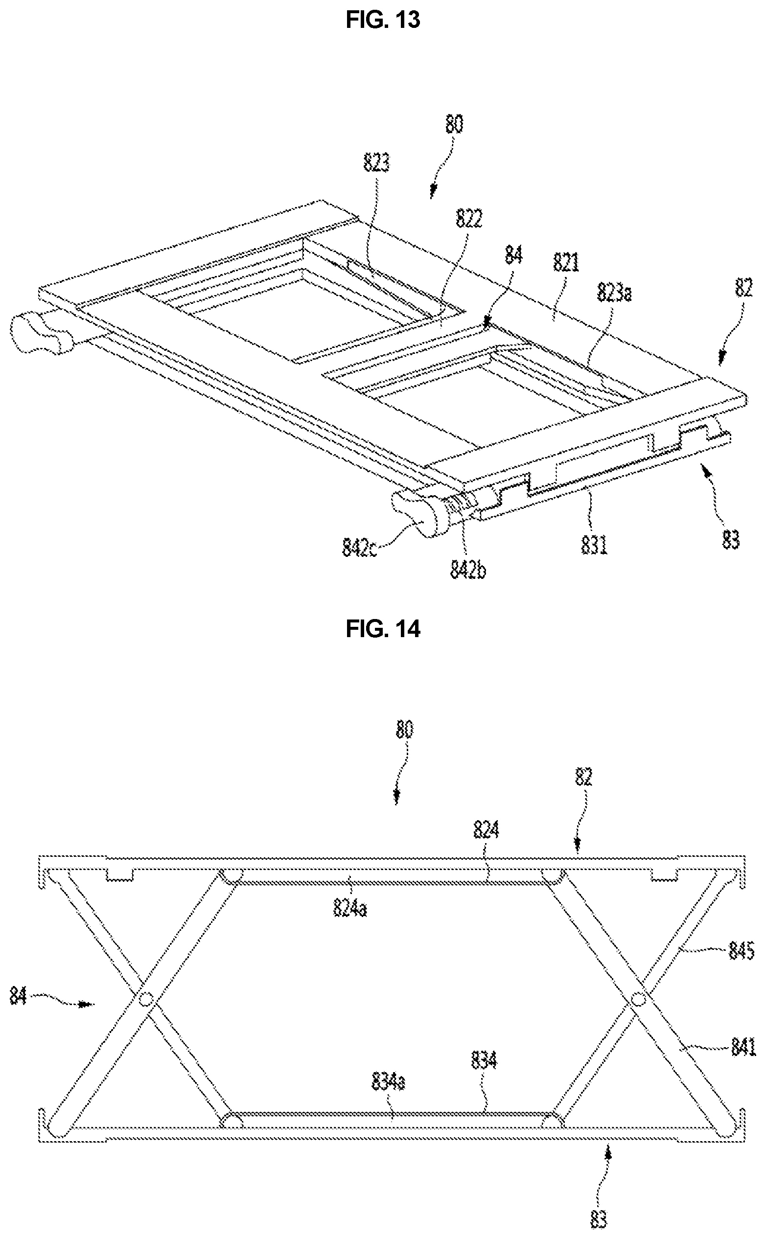
D00014

D00015

D00016

D00017

D00018

D00019

D00020

D00021

D00022

D00023

D00024

D00025

D00026

XML
uspto.report is an independent third-party trademark research tool that is not affiliated, endorsed, or sponsored by the United States Patent and Trademark Office (USPTO) or any other governmental organization. The information provided by uspto.report is based on publicly available data at the time of writing and is intended for informational purposes only.
While we strive to provide accurate and up-to-date information, we do not guarantee the accuracy, completeness, reliability, or suitability of the information displayed on this site. The use of this site is at your own risk. Any reliance you place on such information is therefore strictly at your own risk.
All official trademark data, including owner information, should be verified by visiting the official USPTO website at www.uspto.gov. This site is not intended to replace professional legal advice and should not be used as a substitute for consulting with a legal professional who is knowledgeable about trademark law.