Vertical Fire Pit
GIUNTOLI; DAVID M ; et al.
U.S. patent application number 17/062943 was filed with the patent office on 2021-01-21 for vertical fire pit. The applicant listed for this patent is PETER M 0N, DAVID M GIUNTOLI, WALTER KAIHATU, PAUL ZAMAN. Invention is credited to PETER M 0N, DAVID M GIUNTOLI, WALTER KAIHATU, PAUL ZAMAN.
| Application Number | 20210018181 17/062943 |
| Document ID | / |
| Family ID | 1000005134878 |
| Filed Date | 2021-01-21 |


| United States Patent Application | 20210018181 |
| Kind Code | A1 |
| GIUNTOLI; DAVID M ; et al. | January 21, 2021 |
VERTICAL FIRE PIT
Abstract
A vertical fire pit with a cap to fully enclose a vertical tube having perforations, supported by a plate and base to hold one or more logs in a vertical position. The plate may be non-perforated to allow for collection of ash and leftover unburned log pieces at the bottom of the vertical tube or the plate may be perforated so that ash may fall into an ashtray allowing for easy collection and clean-up.
| Inventors: | GIUNTOLI; DAVID M; (SAN DIEGO, CA) ; 0N; PETER M; (CARLSBAD, CA) ; KAIHATU; WALTER; (ENCINITAS, CA) ; ZAMAN; PAUL; (JAMUL, CA) | ||||||||||
| Applicant: |
|
||||||||||
|---|---|---|---|---|---|---|---|---|---|---|---|
| Family ID: | 1000005134878 | ||||||||||
| Appl. No.: | 17/062943 | ||||||||||
| Filed: | October 5, 2020 |
Related U.S. Patent Documents
| Application Number | Filing Date | Patent Number | ||
|---|---|---|---|---|
| 14719188 | May 21, 2015 | |||
| 17062943 | ||||
| Current U.S. Class: | 1/1 |
| Current CPC Class: | F24B 3/00 20130101 |
| International Class: | F24B 3/00 20060101 F24B003/00 |
Claims
1. A fire pit apparatus for burning one or more logs to create a fire, comprising, in combination: an elongated vertical fire chamber having an elongated central axis and cross-sections oriented perpendicularly to said elongated central axis; all of said cross-sections are substantially identical in size and shape; each of the logs having a central elongated axis; said elongated vertical fire chamber being designed, dimensioned and constructed to receive therein a first one of the logs only in a vertical orientation with the central elongated axis of said first one of the logs oriented substantially parallel to said elongated central axis of said elongated vertical fire chamber; said elongated vertical fire chamber being designed, dimensioned and constructed to receive therein a second one of the logs only in a vertical orientation with said central elongated axis of said second one of the logs oriented substantially parallel to said elongated central axis of said elongated vertical fire chamber, and to receive said second one of the logs in said vertical orientation on top of an end of a partially-consumed first log such that the fire will continue to burn without interruption; said elongated vertical fire chamber being designed, dimensioned and constructed so that it holds the logs only vertically on top of one another in said elongated vertical fire chamber which prevents the logs from sitting, resting, or burning side-by-side; said elongated vertical fire chamber being designed, dimensioned and constructed to be in close proximity to the logs therein so that the logs can only be stacked vertically on top of one another end-to-end; and support means to support said elongated vertical fire chamber.
2. The apparatus of claim 1, including: an ashtray.
3. The apparatus of claim 1, wherein: said support means includes a base assembly.
4. The apparatus of claim 2, wherein: said support means includes a base assembly.
5. The apparatus of claim 3, wherein: said base assembly includes a plurality of support legs.
6. The apparatus of claim 4, wherein: said base assembly includes a plurality of support legs.
7. The apparatus of claim 1, wherein: each of the logs has the shape of a substantially rectangular prism (15).
8. The apparatus of claim 2, wherein: each of the logs has the shape of a substantially rectangular prism (15).
9. The apparatus of claim 3, wherein: each of the logs has the shape of a substantially rectangular prism (15).
10. The apparatus of claim 4, wherein: each of the logs has the shape of a substantially rectangular prism (15).
11. The apparatus of claim 5, wherein: each of the logs has the shape of a substantially rectangular prism (15).
12. The apparatus of claim 6, wherein: each of the logs has the shape of a substantially rectangular prism (15).
13. The apparatus of claim 1, wherein: said elongated vertical fire chamber is comprised of a plurality of flat rectangular side assemblies which have a height at least three times greater than the width (FIG. 1).
14. The apparatus of claim 6, wherein: said elongated vertical fire chamber is comprised of a plurality of flat rectangular side assemblies which have a height at least three times greater than the width (FIG. 1).
15. The apparatus of claim 7, wherein: said elongated vertical fire chamber is comprised of a plurality of flat rectangular side assemblies which have a height at least three times greater than the width (FIG. 1).
16. A fire pit apparatus capable of burning one or more logs to create a fire, comprising, in combination: an elongated vertical fire chamber having an elongated central axis and cross-sections oriented perpendicularly to said elongated central axis; all of said cross sections are substantially identical in size and shape; each of the logs having a central elongated axis; said elongated vertical fire chamber being capable of receiving therein a first one of the logs only in a vertical orientation with the central elongated axis of said first one of the logs being oriented substantially parallel to said elongated central axis of said elongated vertical fire chamber; said elongated vertical fire chamber being capable of receiving therein a second one of the logs only in a vertical orientation with said central elongated axis of said second one of the logs being oriented substantially parallel to said elongated central axis of said elongated vertical fire chamber, and being capable of receiving therein said second one of the logs in said vertical orientation on top of an end of a partially-consumed first log so that the fire will continue to burn without interruption; said elongated vertical fire chamber being capable of holding therein the logs only vertically on top of one another in said elongated vertical fire chamber which prevents the logs from sitting, resting, or burning side-by-side; said elongated vertical fire chamber being capable of holding therein the logs in close proximity to inner walls of said elongated vertical fire chamber so that the logs can only be stacked vertically on top of one another end-to-end; and support means capable of supporting said elongated vertical fire chamber.
17. The apparatus of claim 16, including: a tray capable of holding ashes.
18. The apparatus of claim 16, wherein: said elongated vertical fire chamber is capable of having a height at least three times greater than the width of said elongated vertical fire chamber (FIG. 1);
19. A fire pit apparatus for burning one or more logs to create a fire, comprising, in combination: a base assembly including a plurality of support legs; an ashtray; a perforated plate positioned above said ashtray; said base assembly is positioned underneath said ashtray and underneath said perforated plate; an elongated vertical fire tube comprised of a plurality of flat rectangular side assemblies which have a height at least three times greater than the width (FIG. 1); said elongated vertical tube includes a plurality of perforations covered by a mesh screen located inside of and adjacent to the vertical side; an elongated vertical fire tube having an elongated central axis and cross sections oriented perpendicularly to said elongated central axis; all of said cross-sections are substantially identical in size and shape; each of the logs having a central elongated axis; said elongated vertical fire tube being designed, dimensioned and constructed to receive therein a first one of the logs only in a vertical orientation with the central elongated axis of said first one of the logs oriented substantially parallel to said elongated central axis of said elongated vertical fire tube; said elongated vertical fire tube being designed, dimensioned and constructed to receive therein a second one of the logs only in a vertical orientation with said central elongated axis of said second one of the logs oriented substantially parallel to said elongated central axis of said elongated vertical fire tube, and to receive therein said second one of the logs in said vertical orientation on top of an end of a partially-consumed first log so that the fire will continue to burn without interruption; said elongated vertical fire tube being designed, dimensioned and constructed so that it holds the logs only vertically on top of one another in said elongated vertical fire tube which prevents the logs from sitting, resting, or burning side-by-side; said elongated vertical fire tube being designed, dimensioned and constructed to be in close proximity to the logs therein so that the logs can only be stacked vertically on top of one another end-to-end; said elongated vertical fire tube houses the first log as a fuel source for the fire pit apparatus, and further wherein the first log is positioned in a vertical orientation within the tube parallel to the orientation of the side assemblies of said elongated vertical fire tube; a cap fitting over the top of said elongated vertical fire tube; said cap is connected to said elongated vertical fire tube via a hinge; and said cap includes a perforated mesh-covered opening.
20. The apparatus of claim 19, wherein: each of the logs has the shape of a substantially rectangular prism (15).
Description
RELATED APPLICATIONS
[0001] This application claims the benefit of priority of U.S. Provisional Patent Application No. 62/086,703 filed on Dec. 2, 2014, the disclosure of which is hereby incorporated by reference in its entirety.
FIELD OF INVENTION
[0002] The present invention pertains generally to fire pits. More particularly, the present invention pertains to a vertical fire pit which may support one or more fire logs which may be vertically stacked on top of each other in the vertical position as the previous log burns. The log is placed in a perforated vertical tube for optimal viewing pleasure, while the burnt ash may fall and collect at the bottom or underneath the vertical tube, providing for easy collection and removal of the ash.
[0003] Fire pits in the vertical position are known in the prior art. The majority are targeted to provide a visually attractive fire pit by displaying the fire in different shaped pits or towers with different types of shapes cut out.
[0004] U.S. Pat. No. 8,028,690 issued Oct. 4, 2011 to Lohaus discloses a tower resting or coupled to a surface with the option of using multiple fuel sources, including coal, wood or paper. This invention contains a base assembly which allows for a fuel source to be contained within the body of the tower. The base and tower connect with a number of cut-out portions to allow for lighting of the fuel source but no containment of the burnt ash. However, unlike the present invention, Lohaus does not disclose a cap to prevent fly away ash. Additionally, the ash from burnt fuel accumulates in the bottom of the tower instead of being collected in a separate, self-contained structure for easy collection and disposal.
[0005] U.S. Patent Publication No. 2012/0090589 by Fisher discloses a fire pit formed in the shape of a bottle which may be decorated with a branded beverage logo. This bottle shaped fire pit does not provide for logs to be used in a vertical position and fails to disclose the means by which embers and ash is collected or disposed of.
[0006] One object of the present invention provides the features described herein as well as additional advantages of providing a vertical fire pit with a fully enclosed vertical tube for easy clean-up of ash and leftover unburned log pieces, providing perforations in the vertical tube for viewing pleasure, allowing the addition of full or partial length logs on top of an existing fire, taking up less space, and is portable.
SUMMARY OF THE INVENTION
[0007] The present invention is a vertical fire pit which holds one or more logs in the vertical position.
[0008] It is an object of the present invention to provide a vertical fire pit wherein the viewing experience by the user is enhanced by the inclusion of vertical tubes with an assortment of perforations.
[0009] It is another object of the present invention to provide a vertical fire pit capable of receiving another log, full length or partial length, into the fire on top of ash from consumed fuel.
[0010] It is another object of the present invention to provide a vertical fire pit that takes up less space and is therefore more versatile for varied use.
[0011] It is still another object of the present invention to provide a vertical fire pit with a fully enclosed vertical tube to prevent the falling over of logs.
[0012] It is a further object of the present invention to provide a vertical fire pit capable of preventing cinders from becoming airborne through the use of a cap.
[0013] It is further still an object of the present invention to provide a vertical fire pit amenable to easy collection and clean-up of ash.
BRIEF DESCRIPTION OF THE DRAWINGS
[0014] The advantages of this invention, as well as the invention itself, will be best understood from the accompanying drawings, taken in conjunction with the accompanying description, in which similar parts, and in which:
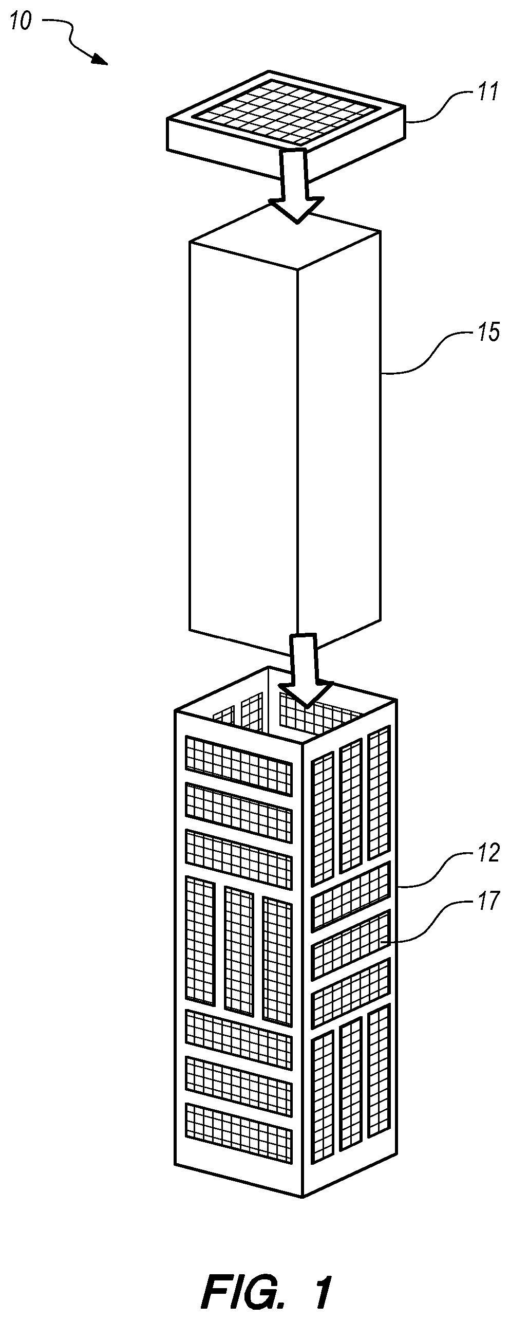
[0015] FIG. 1 illustrates an exploded perspective view of a vertical fire pit tube assembly;
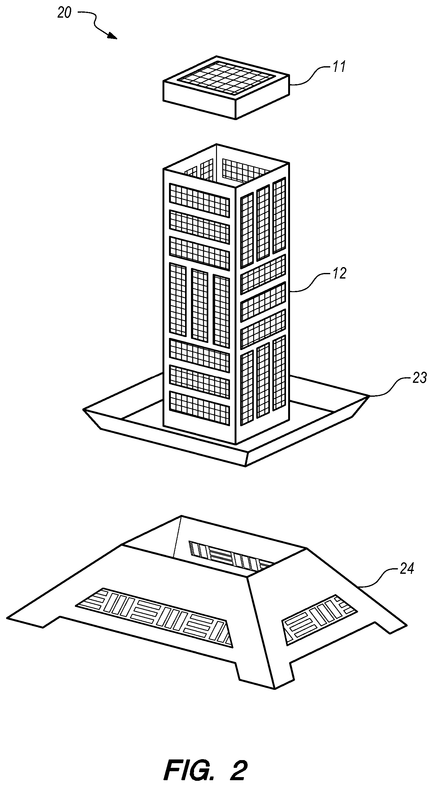
[0016] FIG. 2 illustrates an exploded perspective view of a vertical fire pit with a stand;
[0017] FIG. 3 illustrates a close-up perspective view of a vertical fire pit tube with a slip cap;
[0018] FIG. 4 illustrates a close-up side view of a vertical fire pit tube with a hinged cap;
[0019] FIG. 5 illustrates a deconstructed view of a vertical fire pit tube as shown in FIG. 2;
[0020] FIG. 6 illustrates a deconstructed view of one side of the vertical fire pit tube as shown FIG. 5;
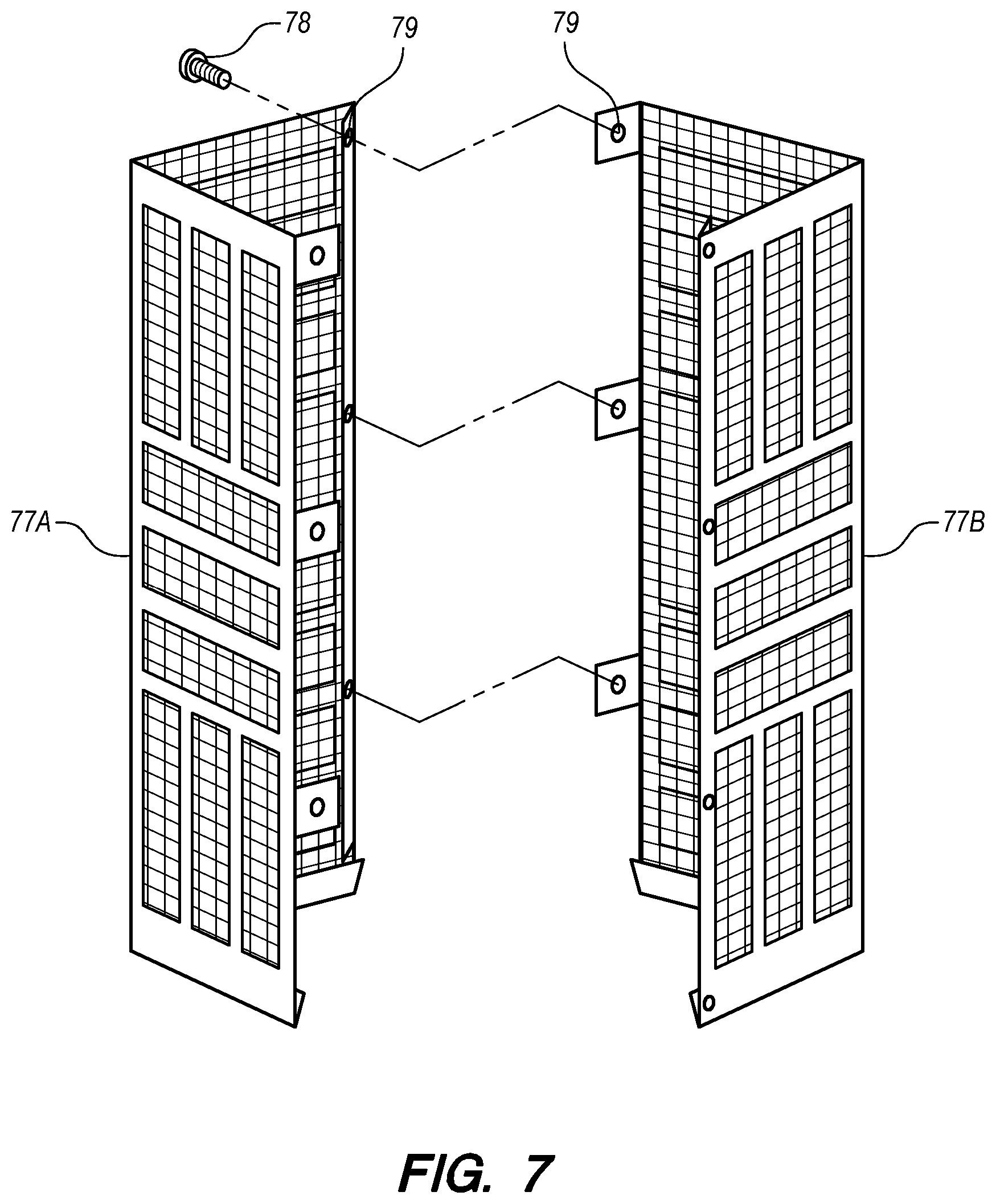
[0021] FIG. 7 illustrates a deconstructed view of two halves of a mechanically fastened vertical fire pit tube;
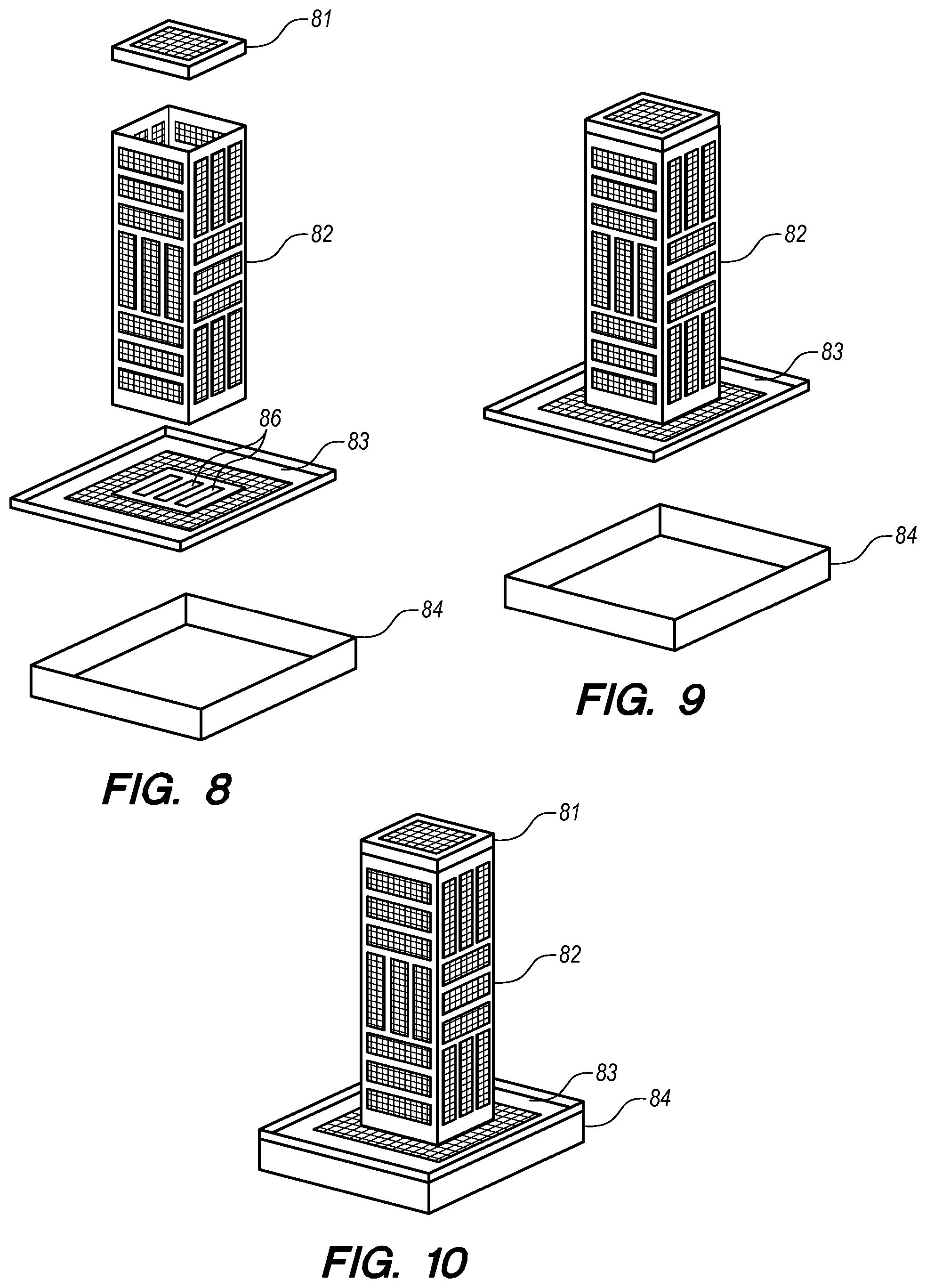
[0022] FIG. 8 illustrates an exploded perspective view of an alternative vertical fire pit with an ashtray stand;
[0023] FIG. 9 illustrates a perspective view of the vertical fire pit disconnected from the ashtray;
[0024] FIG. 10 illustrates a perspective view of the fully assembled vertical fire pit; and
[0025] FIG. 11 illustrates a side view of a fully assembled vertical fire pit during use, and how an additional log will be added to the existing fire.
DETAILED DESCRIPTION OF THE INVENTION
[0026] FIG. 1 illustrates a vertical fire pit of the present invention. The vertical fire pit 10 is comprised of a perforated vertical tube 12, a fuel insert (i.e. log) 15, and a cap 11. By way of example only, the perforated vertical tube 12 may be comprised of four vertical side assemblies 13, each side assembly containing a plurality of cut-out sections 17. Alternatively, the perforated vertical tube 12 may be any shape desirable for a pleasing aesthetic affect. The perforated vertical tube 12 encloses a fuel source 15 such as a manufactured log or natural wood log. This vertical tube 12 holds one "log" such that its longest dimension is vertical. A cap 11 restricts the fuel source to the interior of the perforated vertical tube 12 thereby preventing partially burned fuel, such as ash, from escaping from the perforated vertical tube 12. In a preferred embodiment, the cut-outs 17 are covered with mesh screen.
[0027] With reference to FIG. 2, shown is a first embodiment of the vertical fire pit 20. The perforated vertical tube 12 is attached thereon a non-perforated plate 23 which further rests upon a stand 24. A fuel source 15 (not shown) is placed in the perforated vertical tube 12 and is fully enclosed therein when a cap 11 is placed on top of perforated vertical tube 12 preventing fly-away embers during use. In the present embodiment, burnt ash and unburned log remnants may remnants may fall and collect in the plate 23 preventing fly-away embers during use providing easy disposal of ash by disconnecting the plate 23 from the perforated vertical tube 12.
[0028] With reference to FIG. 3, shown is a close-up perspective view of a perforated vertical tube 32 from FIG. 1 or FIG. 2 with a slip cap 31 that fits over the top most end. Slip cap 31 slips onto the and of the perforated vertical tube 32 to fully enclose the fuel source (not shown). In the present embodiment, the slip cap 31 is slightly larger in dimension than the dimension of the perforated vertical tube 32 such that the slip cap 31 rests on the top of the perforated vertical tube 32 with a short lip 35 extending down to effectively seal the ad closed. Optionally, the slip cap 31 may be further comprised of a perforated, mesh opening 37 to allow flame and smoke to escape through the slip 31 cap during use.
[0029] With reference to FIG. 4, shown is a close-up side view of a perforated vertical tube 42 with a hinged cap 41. Hinged cap 41 is connected to a perforated vertical tube 42 via a hinge 48, which provides for easy opening and closing top of the perforated vertical tube 42. Similar to the slip cap (not shown), the hinged cap 41 is slightly larger in dimension than the dimension of the perforated vertical tube 42 such that the hinged cap 41 rests on the top of the perforated vertical tube 42 with a short lip 45 extending down to effectively seal the top most end closed. Optionally, the hinged cap 41 may be further comprised of a perforated, mesh opening (not shown) to allow flame and smoke to escape through the hinged cap during use.
[0030] With reference to FIG. 5, shown is a deconstructed perforated vertical tube of the present invention. A plurality of side assemblies 57 are attached via vertical pins 58. Each side assembly 57 contains hinge knuckles 59 along the opposing vertical edges of each side assembly 57. Two side assemblies 57A and 57B may be fit together at a 90 degree angle via the hinge knuckles 59 and placement of vertical pins 58 inserted in the hinge knuckles 59. Alternatively the side assemblies may be any shape desired such that the perforated vertical tubes of the present invention are comprised of any number of side assemblies.
[0031] With reference to FIG. 6, shown is a deconstructed view of a single side assembly as shown in FIG. 5. Each side assembly 57 is comprised of apiece of sheet metal 60 placed over a mesh screen 61. The sheet metal 60 may have any shape cut-outs desired for a variety of aesthetic affects during use. The screen 61 is placed in the grooves 62 of the inner side of the sheet metal 60.
[0032] With reference to FIG. 7, shown is a deconstructed view of two halves of a mechanically fastened vertical tube of the present invention. Two halves of the vertical tube 77A and 77B are attached via a plurality of screws 78. Each half 77A and 77B contains a plurality of corresponding screw openings 79 along the edges of each half 77A and 77B. Each half 77A and 77B may be fit together at a 90 degree angle via the plurality of screw openings 79 and placement of the plurality of screws 78 inserted in the corresponding screw openings 79.
[0033] With reference to FIG. 8, shown is an exploded view of an alternative vertical fire pit with an ashtray stand. The perforated vertical tube 82 is positioned above and attached to a horizontal plate 83. The horizontal plate 83 further includes openings 86 to allow ash to drop into the tray 84 underneath the plate 83. Alternatively, the ashtray stand may be any shape desirable in order to achieve a variety of aesthetic effects during use.
[0034] With reference to FIG. 9, shown is a vertical fire pit top assembly wherein the top assembly is removed from the ashtray. Burnt ash may be collected in the tray 84 as it falls through the openings (not shown) in the perforated plate 83. Once the tray 84 is full of ash it may easily be emptied by lifting up and removing the perforated plate 83 and vertical tube 84.
[0035] With reference to FIG. 10, shown is a fully assembled vertical fire pit shown in FIG. 8 and FIG. 9. The perforated vertical tube 82 is positioned above and attached to a horizontal plate 83 which in turn sits upon ash tray 84. Alternatively, the ashtray 84 may be any shape desirable in order to achieve a variety of aesthetic effects during use.
[0036] With reference to FIG. 11, shown is a side view of a fully assembled vertical fire pit during use. When in use, the ash 100 from consumed log 15 falls to the bottom of the vertical tube 12 and through the plate (not shown) into the ashtray (not shown) sitting on top stand 27. Once the fuel source diminishes or is consumed, additional fuel in the form of a full length log 15 or partial length log 16 may be placed directly on top of the existing fire or ash 100.
[0037] One embodiment of the present invention provides a vertical fire pit for use in areas of limited space such as balconies and patios.
[0038] Another embodiment of the present invention provides a vertical fire pit that is aesthetically pleasing to use.
[0039] Yet another embodiment of the present invention provides a vertical fire pit wherein the fuel source is oriented vertically during use.
[0040] A further embodiment of the present invention provides a vertical fire pit wherein a user may add a full or partial log to the fire pit as the previous fuel source is consumed.
[0041] Additional embodiment of the present invention provided that as the vertically held fuel is burning, additional fuel, log, can will be added to the top and held vertical as well. So that both the burning log and just added log are all vertically aligned.
[0042] Still another embodiment of the present invention provides a vertical fire pit wherein the fuel source is fully enclosed within the vertical tube causing ash and debris to fall and collect in a plate or ashtray for easy disposal and clean-up.
[0043] A further embodiment of the present invention provides a vertical fire pit with a cap which inhibits cinders from becoming airborne.
[0044] The foregoing detailed description is not to be taken in a limiting sense, and the scope of the present invention is defined by the appended claims and their equivalents. Although more than one embodiment has been presented, one skilled in the art will appreciate that various modifications are possible. Such variations will not materially alter the nature of the invention. Many embodiments may be conceived and may not achieve all the advantages of some embodiments, particularly preferred embodiments, yet the absence of a particular advantage shall not be construed to necessarily mean that such an embodiment is outside the scope of the present invention.
* * * * *
D00000
D00001
D00002
D00003
D00004
D00005
D00006
D00007
XML
uspto.report is an independent third-party trademark research tool that is not affiliated, endorsed, or sponsored by the United States Patent and Trademark Office (USPTO) or any other governmental organization. The information provided by uspto.report is based on publicly available data at the time of writing and is intended for informational purposes only.
While we strive to provide accurate and up-to-date information, we do not guarantee the accuracy, completeness, reliability, or suitability of the information displayed on this site. The use of this site is at your own risk. Any reliance you place on such information is therefore strictly at your own risk.
All official trademark data, including owner information, should be verified by visiting the official USPTO website at www.uspto.gov. This site is not intended to replace professional legal advice and should not be used as a substitute for consulting with a legal professional who is knowledgeable about trademark law.