Ball Joint And Dust Cover
NAKAGAWA; Keisuke
U.S. patent application number 16/975474 was filed with the patent office on 2021-01-21 for ball joint and dust cover. This patent application is currently assigned to NOK Corporation. The applicant listed for this patent is NOK CORPORATION. Invention is credited to Keisuke NAKAGAWA.
| Application Number | 20210018038 16/975474 |
| Document ID | / |
| Family ID | 1000005147908 |
| Filed Date | 2021-01-21 |

| United States Patent Application | 20210018038 |
| Kind Code | A1 |
| NAKAGAWA; Keisuke | January 21, 2021 |
BALL JOINT AND DUST COVER
Abstract
A ball joint and a dust cover in which a stable sealing function can be provided even when a space for disposing the dust cover is small are provided. The dust cover includes a deformable body portion, a fixed portion which is provided on one end side of the body portion and is fixed to a socket, and a seal portion provided on the other end side of the body portion. The seal portion has a main seal part which is provided to be slidable relative to a spherical portion side flange and an opposite side flange while sandwiched therebetween. The maximum length of the main seal part in a central axis direction in a state in which no external force is applied thereto is longer than a distance between opposing surfaces of the spherical portion side flange and the opposite side flange, where the central axis direction is a direction in which a central axis of the dust cover extends in a state in which no external force is applied thereto.
| Inventors: | NAKAGAWA; Keisuke; (Shizuoka, JP) | ||||||||||
| Applicant: |
|
||||||||||
|---|---|---|---|---|---|---|---|---|---|---|---|
| Assignee: | NOK Corporation Tokyo JP |
||||||||||
| Family ID: | 1000005147908 | ||||||||||
| Appl. No.: | 16/975474 | ||||||||||
| Filed: | September 30, 2019 | ||||||||||
| PCT Filed: | September 30, 2019 | ||||||||||
| PCT NO: | PCT/JP2019/038575 | ||||||||||
| 371 Date: | August 25, 2020 |
| Current U.S. Class: | 1/1 |
| Current CPC Class: | F16C 11/0623 20130101; F16C 11/0671 20130101 |
| International Class: | F16C 11/06 20060101 F16C011/06 |
Foreign Application Data
| Date | Code | Application Number |
|---|---|---|
| Oct 11, 2018 | JP | 2018-192386 |
Claims
1. A ball joint comprising: a ball joint main body including a ball stud which has a shaft and a spherical portion at one end of the shaft, a socket which has a bearing for the spherical portion and supports the ball stud to be rotatable and swingable, and a coupling member which is coupled to the shaft on a side opposite to the spherical portion; and a dust cover attached to the ball joint main body, wherein the shaft is provided with a spherical portion side flange provided on a spherical portion side and an opposite side flange provided on a side opposite to the spherical portion side across the spherical portion side flange, the dust cover includes a deformable body portion, a fixed portion which is provided on one end side of the body portion and is fixed to the socket, and a seal portion provided on the other end side of the body portion, the seal portion has a main seal part which is provided to be slidable relative to the spherical portion side flange and the opposite side flange while sandwiched therebetween, and a maximum length of the main seal part in a central axis direction in a state in which no external force is applied thereto is longer than a distance between opposing surfaces of the spherical portion side flange and the opposite side flange, where the central axis direction is a direction in which a central axis of the dust cover extends in a state in which no external force is applied thereto.
2. The ball joint according to claim 1, wherein the main seal part includes: a pair of inner circumferential surface side seal protrusions which protrude radially inward and come into slidable contact with an outer circumferential surface of the shaft; and an end surface side seal protrusion which protrudes toward the opposite side flange and comes into slidable contact with an end surface of the opposite side flange.
3. The ball joint according to claim 1, wherein an annular concave is provided on an outer circumferential surface of the seal portion.
4. The ball joint according to claim 1, wherein the seal portion has a contact part between the main seal part and the body portion, the contact part having an inner diameter smaller than an outer diameter of the spherical portion side flange in a state in which no external force is applied thereto and being configured to come into slidable contact with an outer circumferential surface of the spherical portion side flange.
5. A dust cover configured to be attached to a ball joint main body, the ball joint main body including a ball stud which has a shaft and a spherical portion at one end of the shaft, a socket which has a bearing for the spherical portion and supports the ball stud to be rotatable and swingable, and a coupling member which is coupled to the shaft on a side opposite to the spherical portion, the shaft being provided with a spherical portion side flange provided on a spherical portion side and an opposite side flange provided on a side opposite to the spherical portion side across the spherical portion side flange, and the dust cover comprising: a deformable body portion; a fixed portion which is provided on one end side of the body portion and is fixed to the socket; and a seal portion provided on the other end side of the body portion, wherein the seal portion has a main seal part which is provided to be slidable relative to the spherical portion side flange and the opposite side flange while sandwiched therebetween, and a maximum length of the main seal part in a central axis direction in a state in which no external force is applied thereto is longer than a distance between opposing surfaces of the spherical portion side flange and the opposite side flange, where the central axis direction is a direction in which a central axis of the dust cover extends in a state in which no external force is applied thereto.
6. The dust cover according to claim 5, wherein the main seal part includes: a pair of inner circumferential surface side seal protrusions which protrude radially inward and come into slidable contact with an outer circumferential surface of the shaft; and an end surface side seal protrusion which protrudes toward the opposite side flange and comes into slidable contact with an end surface of the opposite side flange.
7. The dust cover according to claim 5, wherein an annular concave is provided on an outer circumferential surface of the seal portion.
8. The dust cover according to claim 5, wherein the seal portion has a contact part between the main seal part and the body portion, the contact part having an inner diameter smaller than an outer diameter of the spherical portion side flange in a state in which no external force is applied thereto and being configured to come into slidable contact with an outer circumferential surface of the spherical portion side flange.
Description
TECHNICAL FIELD
[0001] The present disclosure relates to a ball joint and a dust cover which are provided in a vehicle or the like.
BACKGROUND ART
[0002] Conventionally, a dust cover is used for a ball joint provided in various devices such as a vehicle in order to prevent water, dust, and the like from entering a joint portion and prevent grease from flowing out of the joint portion. In such a dust cover, in order to provide a stable sealing function, when a ball stud swings relative to a socket that constitutes a ball joint, a body portion of the dust cover is desired to be deformed to follow it and there needs to be no gap formed in a seal portion.
[0003] However, in recent years, due to a trend of miniaturization of devices in addition to increase in a swing angle of a ball stud relative to a socket, a space for placing a dust cover can be narrow, and thus it may be difficult to meet the above mentioned desire with conventional structures.
CITATION LIST
Patent Literature
[PTL 1]
[0004] Japanese Patent Application Publication No. 2012-1028404
[PTL 2]
[0004] [0005] Japanese Utility model Application Publication No. H07-10543
SUMMARY OF INVENTION
Technical Problem
[0006] An object of the present disclosure is to provide a ball joint and a dust cover which can provide a stable sealing function even when a space for disposing a dust cover is narrow.
Solution to Problem
[0007] The present disclosure employs the following means in order to achieve the object.
[0008] That is, a ball joint of the present disclosure is a ball joint including:
[0009] a ball joint main body including [0010] a ball stud which has a shaft and a spherical portion at one end of the shaft, [0011] a socket which has a bearing for the spherical portion and supports the ball stud to be rotatable and swingable, and [0012] a coupling member which is coupled to the shaft on a side opposite to the spherical portion; and
[0013] a dust cover attached to the ball joint main body, wherein
[0014] the shaft is provided with [0015] a spherical portion side flange provided on a spherical portion side and [0016] an opposite side flange provided on a side opposite to the spherical portion side across the spherical portion side flange,
[0017] the dust cover includes [0018] a deformable body portion, [0019] a fixed portion which is provided on one end side of the body portion and is fixed to the socket, and [0020] a seal portion provided on the other end side of the body portion,
[0021] the seal portion has a main seal part which is provided to be slidable relative to the spherical portion side flange and the opposite side flange while sandwiched therebetween, and
[0022] a maximum length of the main seal part in a central axis direction in a state in which no external force is applied thereto is longer than a distance between opposing surfaces of the spherical portion side flange and the opposite side flange, where the central axis direction is a direction in which a central axis of the dust cover extends in a state in which no external force is applied thereto.
[0023] The dust cover of the present disclosure is a dust cover configured to be attached to a ball joint main body,
[0024] the ball joint main body including [0025] a ball stud which has a shaft and a spherical portion at one end of the shaft, [0026] a socket which has a bearing for the spherical portion and supports the ball stud to be rotatable and swingable, and [0027] a coupling member which is coupled to the shaft on a side opposite to the spherical portion,
[0028] the shaft being provided with [0029] a spherical portion side flange provided on a spherical portion side and [0030] an opposite side flange provided on a side opposite to the spherical portion side across the spherical portion side flange, and
[0031] the dust cover including [0032] a deformable body portion, [0033] a fixed portion which is provided on one end side of the body portion and is fixed to the socket, and [0034] a seal portion provided on the other end side of the body portion, wherein
[0035] the seal portion has a main seal part which is provided to be slidable relative to the spherical portion side flange and the opposite side flange while sandwiched therebetween, and
[0036] a maximum length of the main seal part in a central axis direction in a state in which no external force is applied thereto is longer than a distance between opposing surfaces of the spherical portion side flange and the opposite side flange, where the central axis direction is a direction in which a central axis of the dust cover extends in a state in which no external force is applied thereto.
[0037] According to these disclosures, since the main seal part of the dust cover is configured to be sandwiched between the spherical portion side flange and the opposite side flange provided on the shaft of the ball stud, a sealing function thereof can be achieved even when a space of a portion with which the main seal part is in close contact is narrow.
[0038] The main seal part may include [0039] a pair of inner circumferential surface side seal protrusions which protrude radially inward and come into slidable contact with an outer circumferential surface of the shaft, and [0040] an end surface side seal protrusion which protrudes toward the opposite side flange and comes into slidable contact with an end surface of the opposite side flange.
[0041] This provides sealing function at both locations between the inner circumferential surface side seal protrusions and the outer circumferential surface of the shaft and between the end surface side seal protrusion and the end surface of the opposite side flange. In addition, since the main seal part is sandwiched between the spherical portion side flange and the opposite side flange provided on the shaft of the ball stud, separation of the inner circumferential surface side seal protrusions from the outer circumferential surface of the shaft is prevented, and separation of the end surface side seal protrusion from the end surface of the opposite side flange is prevented. Further, since the pair of inner circumferential surface side seal protrusions are provided, a space is formed between the pair of inner circumferential surface side seal protrusions, and accordingly, even when the main seal part is sandwiched between the spherical portion side flange and the opposite side flange, the inner circumferential surface side seal protrusions can be deformed to escape into the space. Therefore, deterioration of a sealing performance due to abnormal deformation of the main seal part can be inhibited.
[0042] An annular concave may be provided on an outer circumferential surface of the seal portion.
[0043] The annular concave can inhibit abnormal deformation of the dust cover when the dust cover is deformed such that an outer circumferential surface side part of the body portion on and the outer circumferential surface of the seal portion come closer to each other as the ball stud swings relative to the socket.
[0044] The seal portion may have a contact part between the main seal part and the body portion, the contact part having an inner diameter smaller than an outer diameter of the spherical portion side flange in a state in which no external force is applied thereto and being configured to come into slidable contact with an outer circumferential surface of the spherical portion side flange.
[0045] This achieves more stable sealing performance.
[0046] The above configurations may be employed in combination where possible.
Advantageous Effects of Invention
[0047] According to the present disclosure, a stable sealing function can be provided even when a space for disposing a dust cover is narrow.
BRIEF DESCRIPTION OF DRAWINGS
[0048] FIG. 1 is a schematic cross-sectional view of a ball joint according to an embodiment of the present disclosure.
[0049] FIG. 2 is a partially enlarged cross-sectional view of the ball joint according to the embodiment of the present disclosure.
[0050] FIG. 3 is a schematic cross-sectional view of a dust cover according to an embodiment of the present disclosure.
[0051] FIG. 4 is a partially enlarged cross-sectional view of the dust cover according to the embodiment of the present disclosure.
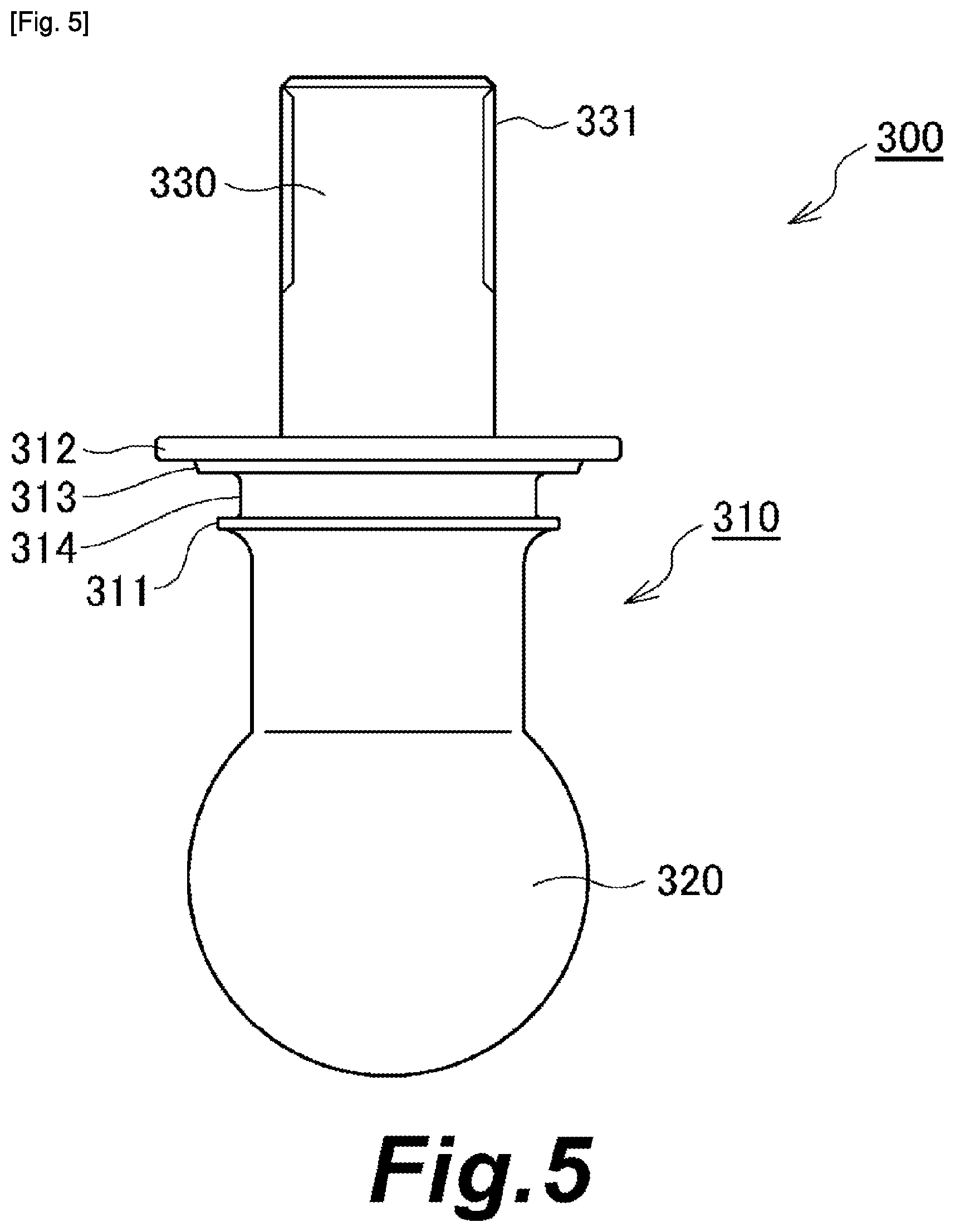
[0052] FIG. 5 is a front view of a ball stud according to an embodiment of the present disclosure.
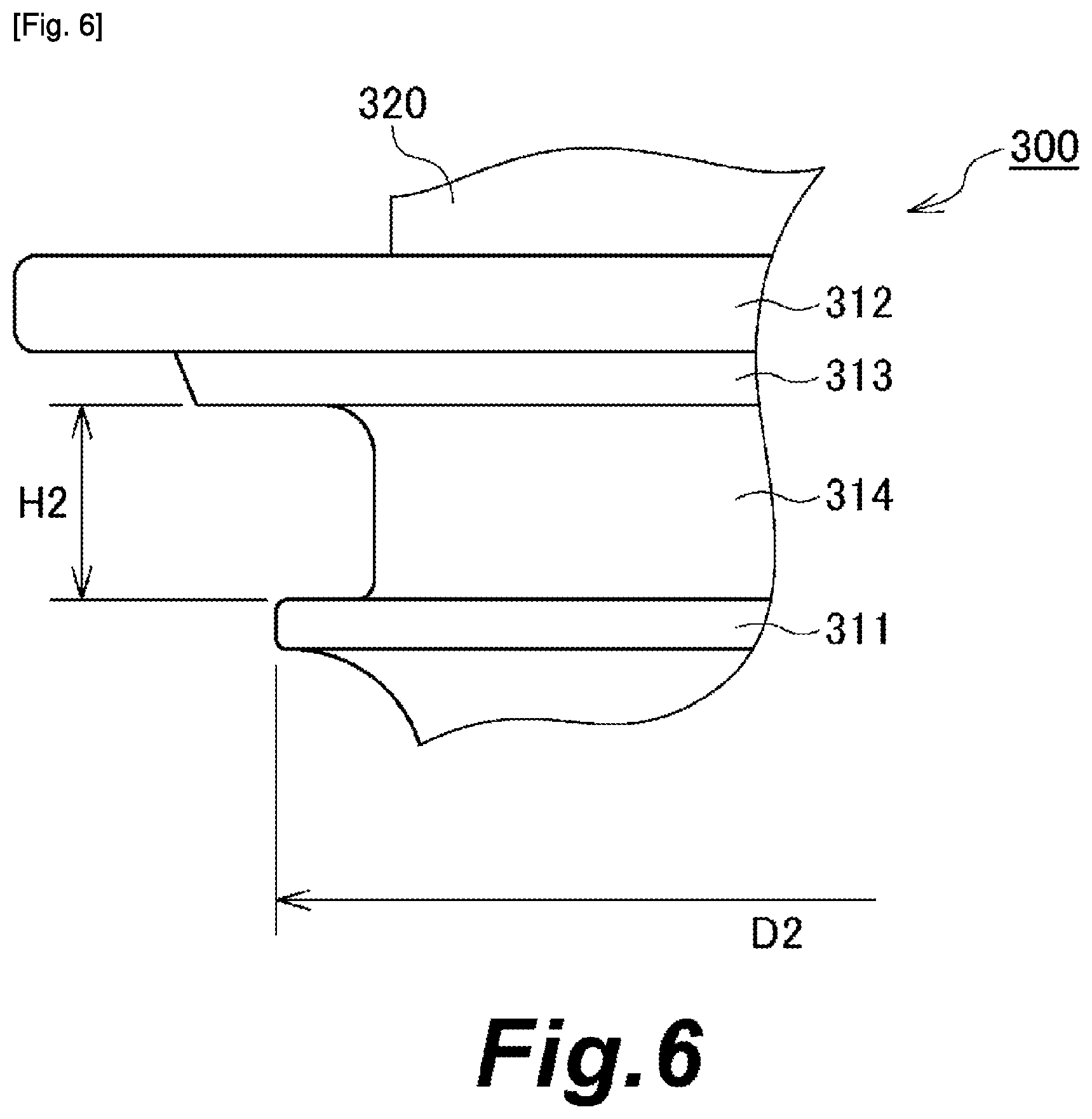
[0053] FIG. 6 is a partially enlarged view of the ball stud according to the embodiment of the present disclosure.
DESCRIPTION OF EMBODIMENTS
[0054] An embodiment for implementing the present disclosure will be illustrated below in detail with reference to the figures. However, dimensions, materials, shapes, relative positions, and the like of the components described in the present embodiment are not intended to limit the scope of the present disclosure thereto unless otherwise specified.
Embodiment
[0055] With reference to FIGS. 1 to 6, a ball joint and a dust cover according to an embodiment of the present disclosure will be described. The ball joint is provided in any of various devices such as a vehicle. In the following description, a direction in which a central axis of the dust cover extends in a state in which no external force is applied thereto is referred to as a "central axis direction."
[0056] <Ball Joint>
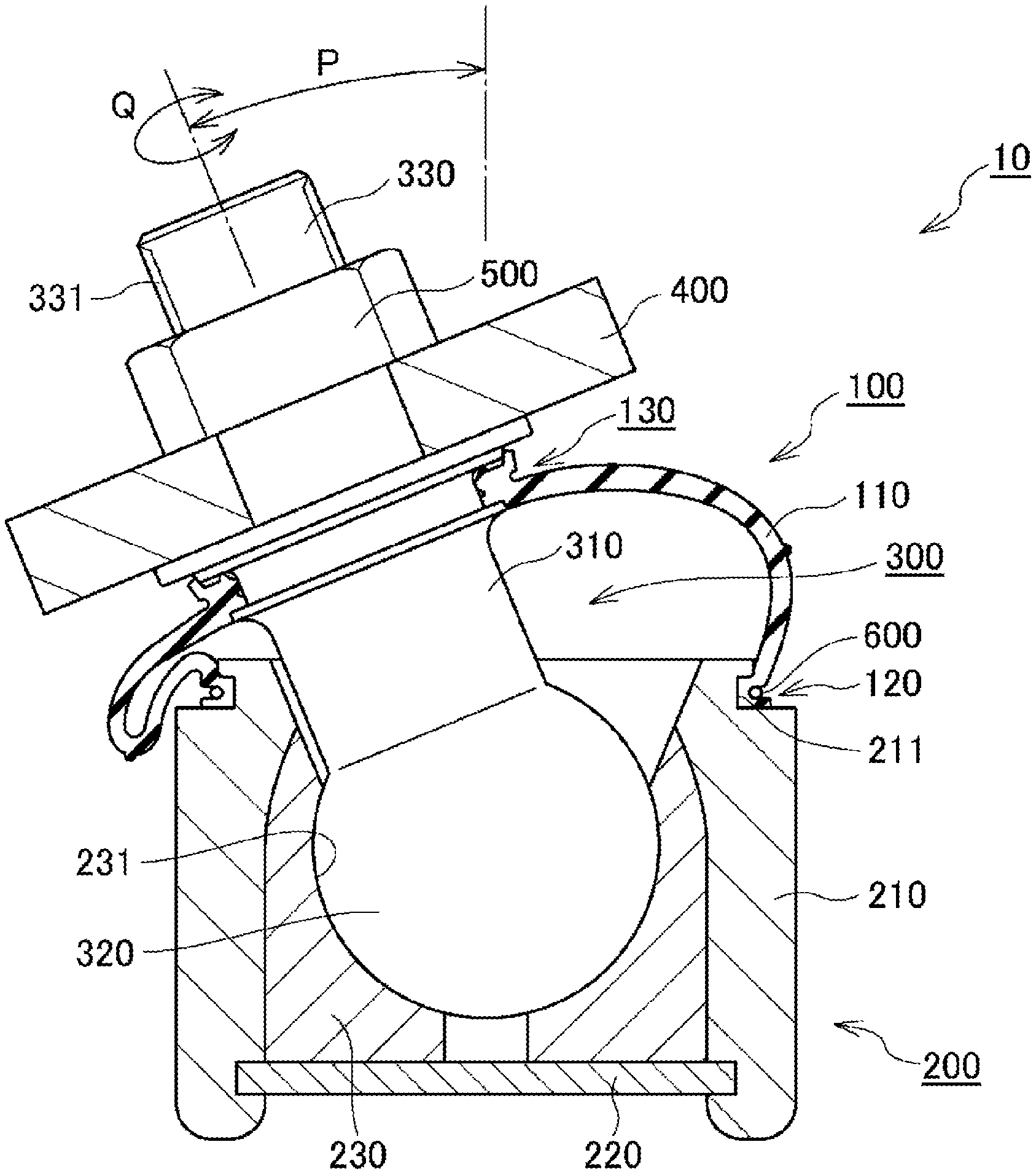
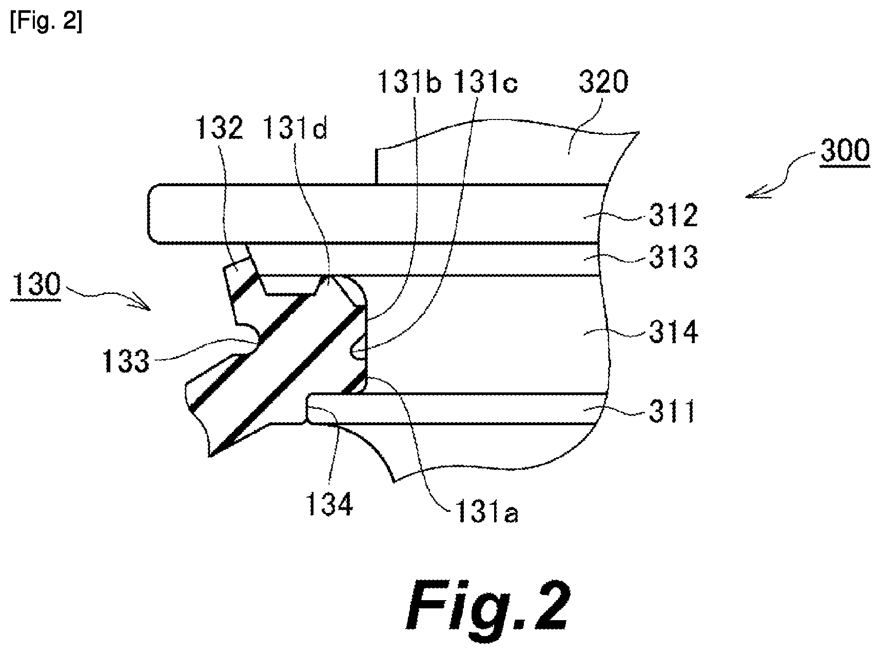
[0057] With reference to FIGS. 1 and 2, an overall configuration and the like of the ball joint will be described. FIG. 1 is a schematic cross-sectional view of the ball joint according to the embodiment of the present disclosure. FIG. 1 is a cross-sectional view in which the dust cover and the like are cut along a plane including a central axis of a shaft of a ball stud provided in the ball joint. FIG. 2 is a partially enlarged cross-sectional view of the ball joint according to the embodiment of the present disclosure, and is a cross-sectional view in which a vicinity of a seal portion of the dust cover is enlarged.
[0058] The ball joint 10 includes a ball joint main body and a dust cover 100 attached to the ball joint main body. The ball joint main body includes a ball stud 300, a socket 200 which supports the ball stud 300 to be rotatable and swingable, and a knuckle 400 serving as a coupling member which is coupled to the shaft 310 of the ball stud 300. The dust cover 100 is made of an elastic material such as rubber.
[0059] The ball stud 300 has a spherical portion 320 at one end of the shaft 310. The socket 200 includes an annular case 210, a bottom plate 220 fixed to a bottom side of the case 210, and a bearing 230 for the spherical portion 320. The bearing 230 has a bearing surface 231 consisting of a spherical surface having the same diameter as a radius of curvature of the spherical portion 320. The knuckle 400 is coupled to the shaft 310 using a nut 500 on a side of the shaft 310 opposite to the spherical portion 320.
[0060] The ball joint 10 includes the dust cover 100 in order to prevent water, dust, and the like from entering a joint portion and to prevent grease from flowing out of the joint portion.
[0061] <Dust Cover>
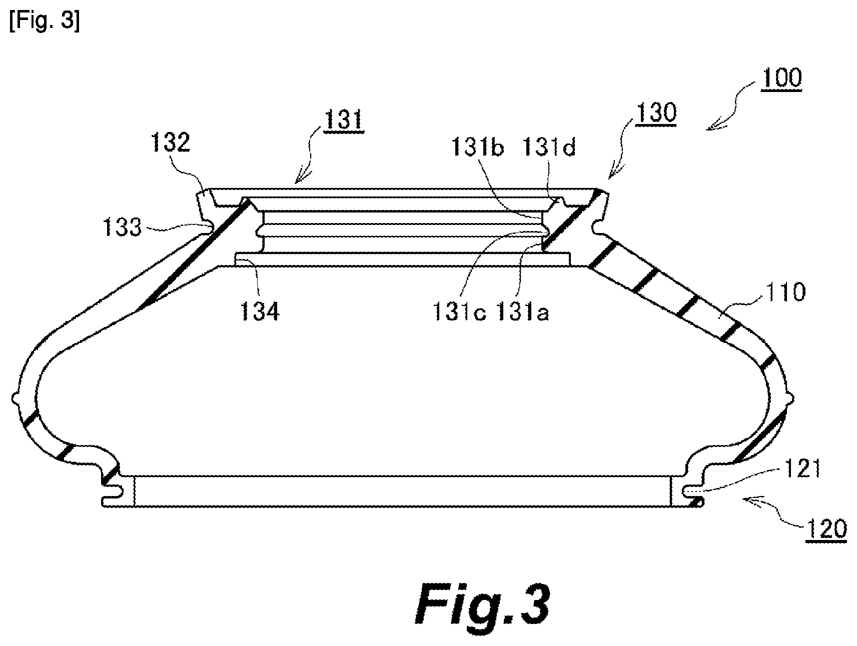
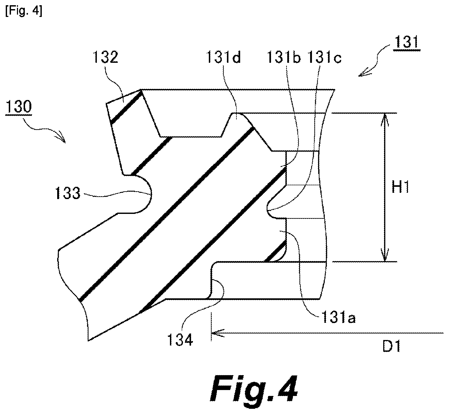
[0062] The dust cover 100 will be described with reference to FIGS. 3 and 4. FIG. 3 is a schematic cross-sectional view of the dust cover 100 according to the embodiment of the present disclosure. FIG. 3 shows a state in which no external force acts on the dust cover 100. When no external force acts on the dust cover 100, the dust cover 100 has a rotationally symmetric shape. FIG. 3 is a cross-sectional view of the dust cover 100 cut along a plane including the central axis of the dust cover 100 in a state in which no external force acts on the dust cover 100. FIG. 4 is a partially enlarged cross-sectional view of the dust cover 100 according to the embodiment of the present disclosure, and is a cross-sectional view in which a vicinity of the seal portion is enlarged.
[0063] The dust cover 100 includes a deformable film-shaped body portion 110, a fixed portion 120 which is provided on one end side of the body portion 110 and is fixed to the socket 200, and the seal portion 130 provided on the other end side of the body portion 110. The body portion 110 is configured such that a central portion thereof swells outward. An annular attachment groove 121 is provided on an outer circumferential surface side of the fixed portion 120. By attaching a fastener 600 to the attachment groove 121, the fixed portion 120 is fixed to an annular notch 211 formed at a tip of the case 210 of the socket 200 (see FIG. 1).
[0064] The seal portion 130 includes a main seal part 131 provided on an inner circumferential surface side thereof, a dust lip 132 provided on an outer circumferential surface side, an annular concave 133 provided near a base part of the dust lip 132 on the outer circumferential surface side, and a contact part 134 provided between the main seal part 131 and the body portion 110. The main seal part 131 includes a pair of annular inner circumferential surface side seal protrusions 131a and 131b that protrude radially inward, and an annular end surface side seal protrusion 131d provided on an end surface side thereof. An annular groove 131c is formed between the pair of inner circumferential surface side seal protrusions 131a and 131b.
[0065] <Ball Stud>
[0066] The ball stud 300 will be described with reference to FIGS. 5 and 6. FIG. 5 is a front view of the ball stud 300 according to the embodiment of the present disclosure. FIG. 6 is a partially enlarged view of the ball stud 300 according to the embodiment of the present disclosure.
[0067] The ball stud 300 has the shaft 310 and the spherical portion 320 provided at one end of the shaft 310. A male screw part 331 is formed on an outer circumferential surface of the other end portion 330 of the shaft 310. The nut 500 is fastened to the male screw part 331. The shaft 310 is provided with a first flange (a spherical portion side flange) 311 provided on the spherical portion 320 side, a second flange 312 and a third flange (an opposite side flange) 313 provided on a side opposite to the spherical portion 320 side across the first flange 311. The second flange 312 and the third flange 313 are provided to be adjacent to each other, and these constitute a stepped flange in which the latter has a smaller outer diameter. A part of the shaft 310 between the first flange 311 and the third flange 313 serves as a seal surface 314 in which the main seal part 131 of the dust cover 100 slides.
[0068] <Relationship Between Seal Portion of Dust Cover and Ball Stud>
[0069] A relationship between the seal portion 130 of the dust cover 100 and the ball stud 300 will be described with reference to FIGS. 1, 2, 4, and 6. In a state in which the dust cover 100 is attached to the ball joint main body, the main seal part 131 is provided to be slidable relative to the first flange 311 and the third flange 313 provided on the shaft 310 of the ball stud 300 while sandwiched therebetween. In the main seal part 131, the pair of inner circumferential surface side seal protrusions 131a and 131b provided to protrude radially inward come into slidable contact with an outer circumferential surface of the shaft 310 (at the seal surface 314). In the main seal part 131, an end surface side seal protrusion 131d provided to project toward the third flange 313 comes into slidable contact with an end surface of the third flange 313. The dust lip 132 of the seal portion 130 comes into slidable contact with an outer circumferential surface of the third flange 313. The contact part 134 of the seal portion 130 comes into slidable contact with an outer circumferential surface of the first flange 311.
[0070] A maximum length of the main seal part 131 in the central axis direction in a state in which no external force is applied thereto is defined as H1 (see FIG. 4). A distance between opposing surfaces of the first flange 311 (spherical portion side flange) and the third flange 313 (opposite side flange) is defined as H2 (see FIG. 6). These are set to satisfy H1>H2. Since the main seal part 131 is compressed by the first flange 311 and the third flange 313, it is more surely sandwiched by them.
[0071] An inner diameter of the contact part 134 in a state in which no external force is applied to the seal portion 130 is defined as D1 (see FIG. 4). An outer diameter of the first flange 311 (spherical portion side flange) is defined as D2 (see FIG. 6). These are set to satisfy D1<D2. Therefore, the contact part 134 comes into slidable contact with the outer circumferential surface of the first flange 311 with an interference.
[0072] The body portion 110 of the dust cover 100 configured as described above is deformed when the ball stud 300 swings relative to the socket 200 as indicated by an arrow P in FIG. 1. When the ball stud 300 rotates relative to the socket 200 as indicated by an arrow Q in FIG. 1, the seal portion 130 slides on the shaft 310 of the ball stud 300 and the like. As a result, the dust cover 100 provides a sealing function regardless of whether the ball stud 300 swings or rotates with respect to the socket 200.
Excellent Points of Ball Joint and Dust Cover According to Present Embodiment
[0073] The main seal part 131 of the dust cover 100 is sandwiched between the first flange 311 and the third flange 313 which are provided on the shaft 310 of the ball stud 300. Thus, even when a space of a part with which the main seal part 131 is in close contact is narrow, a sealing performance thereof is kept.
[0074] The main seal part 131 includes the pair of inner circumferential surface side seal protrusions 131a and 131b and the end surface side seal protrusion 131d. This provides the sealing function at both locations between the inner circumferential surface side seal protrusions 131a and 131b and the outer circumferential surface of the shaft 310, and between the end surface side seal protrusion 131d and the end surface of the third flange 313. Since the main seal part 131 is sandwiched by the first flange 311 and the third flange 313, separation of the inner circumferential surface side seal protrusions 131a and 131b from the outer circumferential surface of the shaft 310 is inhibited, and separation of the end surface side seal protrusion 131d from the end surface of the third flange 313 is inhibited.
[0075] Since the pair of inner circumferential surface side seal protrusions 131a and 131b are provided, the space (the space in a groove of the annular groove 131c) is formed between the pair of inner circumferential surface side seal protrusions 131a and 131b, and accordingly, even when the main seal part 131 is sandwiched between the first flange 311 and the third flange 313, the inner circumferential surface side seal protrusions 131a and 131b can be deformed to escape into the space. Therefore, deterioration of the sealing performance due to abnormal deformation of the main seal part 131 can be inhibited.
[0076] The annular concave 133 provided on an outer circumferential surface of the seal portion 130 can inhibit abnormal deformation of the dust cover 100 when the dust cover 100 is deformed such that a part of the body portion 110 on the outer circumferential surface side and the outer circumferential surface of the seal portion 130 come closer to each other as the ball stud 300 swings relative to the socket 200.
[0077] The contact part 134 of the seal portion 130 that comes into slidable contact with the outer circumferential surface of the first flange 311 achieves more stable sealing performance.
[0078] As described above, according to the ball joint 10 and the dust cover 100, a stable sealing function can be provided even when a space for disposing the dust cover 100 is narrow.
REFERENCE SIGNS LIST
[0079] 10 Ball joint [0080] 100 Dust cover [0081] 110 Body portion [0082] 120 Fixed portion [0083] 121 Attachment groove [0084] 130 Seal portion [0085] 131 Main seal part [0086] 131a, 131b Inner circumferential surface side seal protrusion [0087] 131c Annular groove [0088] 131d End surface side seal protrusion [0089] 132 Dust lip [0090] 133 Annular concave [0091] 134 Contact part [0092] 200 Socket [0093] 210 Case [0094] 211 Notch [0095] 220 Bottom plate [0096] 230 Bearing [0097] 231 Bearing surface [0098] 300 Ball stud [0099] 310 Shaft [0100] 311 First flange (spherical portion side flange) [0101] 312 Second flange [0102] 313 Third flange (opposite side flange) [0103] 314 Seal surface [0104] 320 Spherical portion [0105] 330 Other end portion [0106] 331 Male screw portion [0107] 400 Knuckle [0108] 500 Nut [0109] 600 Fastener
* * * * *
D00000
D00001
D00002
D00003
D00004
D00005
D00006
XML
uspto.report is an independent third-party trademark research tool that is not affiliated, endorsed, or sponsored by the United States Patent and Trademark Office (USPTO) or any other governmental organization. The information provided by uspto.report is based on publicly available data at the time of writing and is intended for informational purposes only.
While we strive to provide accurate and up-to-date information, we do not guarantee the accuracy, completeness, reliability, or suitability of the information displayed on this site. The use of this site is at your own risk. Any reliance you place on such information is therefore strictly at your own risk.
All official trademark data, including owner information, should be verified by visiting the official USPTO website at www.uspto.gov. This site is not intended to replace professional legal advice and should not be used as a substitute for consulting with a legal professional who is knowledgeable about trademark law.