Air Vent With Snap-fit Cover For Foundation Walls
Sykes; William G.
U.S. patent application number 16/919812 was filed with the patent office on 2021-01-21 for air vent with snap-fit cover for foundation walls. The applicant listed for this patent is William G. Sykes. Invention is credited to William G. Sykes.
| Application Number | 20210017759 16/919812 |
| Document ID | / |
| Family ID | 1000005060466 |
| Filed Date | 2021-01-21 |


| United States Patent Application | 20210017759 |
| Kind Code | A1 |
| Sykes; William G. | January 21, 2021 |
AIR VENT WITH SNAP-FIT COVER FOR FOUNDATION WALLS
Abstract
A combination of an air vent for passing air through an opening of a wall around an enclosed area, to facilitate ventilation, and a cover readily installable on and removable from the air vent are disclosed. The air vent includes a peripheral flange surrounding a central opening and a screen fixed to the air vent and covering the central opening. The air vent may include fixed false louvers and may bear surface texturing for esthetics. The cover is dimensioned and configured to overlie the central opening and may be releasably held in place by opposed deflectable tabs formed integrally therewith. Each of the tabs has a projection configured to enter and occupy a corresponding hole in the air vent. The tabs may be deflected to remove the projections from their respective holes, thereby releasing the cover from the air vent.
| Inventors: | Sykes; William G.; (Virginia Beach, VA) | ||||||||||
| Applicant: |
|
||||||||||
|---|---|---|---|---|---|---|---|---|---|---|---|
| Family ID: | 1000005060466 | ||||||||||
| Appl. No.: | 16/919812 | ||||||||||
| Filed: | July 2, 2020 |
Related U.S. Patent Documents
| Application Number | Filing Date | Patent Number | ||
|---|---|---|---|---|
| 16515419 | Jul 18, 2019 | |||
| 16919812 | ||||
| Current U.S. Class: | 1/1 |
| Current CPC Class: | F24F 13/082 20130101; E04B 1/7076 20130101 |
| International Class: | E04B 1/70 20060101 E04B001/70; F24F 13/08 20060101 F24F013/08 |
Claims
1. A combination of an air vent for passing air through an opening of a wall around an enclosed area, to facilitate ventilation, and a cover for blocking air from passing through the opening, wherein the cover is readily installable on and removable from the air vent, the combination comprising: an air vent including a central opening for ventilation, a screen fixed to the air vent and covering the central opening, a planar peripheral flange surrounding the central opening, wherein the peripheral flange occupies a plane perpendicular to a direction of flow of air through the central opening, and false louvers covering the screen, the false louvers arranged to leave the central opening unobstructed for passage of air past the screen; and a cover dimensioned and configured to overlie the central opening in a deployed position and to block air flow through the air vent when the cover is installed, wherein one of the air vents and the cover includes at least one integral deflectable tab configured to engage by snap fit the other of the air vent and the cover, and to releasably couple the air vent to the cover.
2. The combination of claim 1, wherein the other of the air vent and the cover has at least one hole, and the at least one deflectable tab includes a projection configured to enter and occupy the at least one hole in the other of the air vent and the cover when the at least one deflectable tab is not deflected, and to be released from the at least one hole when the deflectable tab is deflected.
3. The combination of claim 2, wherein the air vent has a right side and a left side when installed over the opening of the wall, the at least one deflectable tab comprises a first tab at the right side of the air vent and a second tab at the left side of the air vent; and the at least one hole comprises a first hole at the right side of the air vent and a second hole at the left side of the air vent.
4. The combination of claim 3, wherein the first tab and the second tab are each defined on three sides by a slot formed in the air vent and are attached to the air vent at a living hinge defined on a fourth side.
5. The combination of claim 3, wherein the first tab and the second tab are on the cover, and the first hole and the second hole are in the air vent.
6. The combination of claim 5, wherein the cover comprises an access opening dimensioned and configured to enable a person to insert a finger thereinto and impose pressure on the air vent in a direction releasing the cover from engagement with the air vent.
7. The combination of claim 5, wherein the air vent comprises a perimetric projection perpendicular to the peripheral flange and surrounding the central opening, and the first hole and the second hole are in the perimetric projection of the air vent.
8. The combination of claim 7, wherein the perimetric projection is double walled and hollow in cross section along at least most of a length of the perimetric projection.
9. The combination of claim 7, wherein the air vent further comprises a central wall dividing the central opening into a right portion and a left portion.
10. The combination of claim 9, wherein the false louvers are coupled to the perimetric projection at the right side of the air vent, at the left side of the air vent, and at the central wall of the air vent, and wherein each false louver comprises a gusset perpendicular to the false louver and spanning the respective false louver and the right side and the left side of the air vent, and each gusset seals an end of a respective false louver against loss of air from air flow at the false louver through the air vent to lateral air flow not passing through the air vent.
11. The combination of claim 1, wherein the cover is made substantially from one or more plastic materials by pressure molding.
12. The combination of claim 11, wherein the plastic material comprises ABS (acrylonitrile butadiene styrene) plastic material.
13. The combination of claim 1, further comprising decorative surface texturing on the air vent and on the cover.
Description
RELATED APPLICATION
[0001] This is a Continuation-In-Part application of the U.S. patent application Ser. No. 16/515,419 for AIR VENT WITH SNAP-FIT COVER FOR FOUNDATION WALLS filed Jul. 18, 2019 and which is included by reference herein in its entirety.
FIELD OF THE INVENTION
[0002] The present invention relates to opening covers for building foundation walls having openings in the wall and covers for selectively ventilating a crawl space within, and for preventing exchange of air between the crawl space and ambient air outside the associated building.
BACKGROUND OF THE INVENTION
[0003] Houses and other buildings may have foundation walls projecting above surrounding grade and defining a basement or crawl space within. Particularly in the case of crawl spaces, foundation walls frequently have openings communicating between an enclosed space inside the wall (i.e., the basement or crawl space) The opening provide access and ventilation, and possibly other purposes.
[0004] Crawl spaces and basements, where open to the surrounding atmosphere, are susceptible to becoming objectionably humid. Humidity may promote molds, mildew, and other damaging influences on for example a wooden floor above the basement or crawl space. The aforementioned openings are intended to enable passive ventilation to prevent excessive buildup of humidity. However, there are times when ventilation is undesirable. For example, in cold weather, it may be desirable to exclude relatively cold ambient air from the crawl space or basement. In another example, building owners may prefer to utilize dehumidification equipment, which would obviously benefit from excluding potentially humid ambient air from the enclosed space. It becomes desirable then to provide a cover for the air vent. It would also be desirable to make the cover easy to use and to avoid presence of small articles such as fasteners which could easily become lost when installing or removing the cover.
SUMMARY OF THE INVENTION
[0005] The present invention provides an air vent for openings in basement and crawl space walls which address the above concerns.
[0006] More particularly, the invention contemplates a combination of an air vent for passing air through an opening of a wall around e.g. a basement or crawl space, to facilitate ventilation, and a cover readily installable on and removable from the air vent. The air vent includes a peripheral flange surrounding a central opening and a screen fixed to the air vent and covering the central opening. The air vent may include fixed false louvers and may bear surface texturing for esthetics. The cover is dimensioned and configured to overlie the central opening and may be releasably held in place by opposed deflectable tabs formed integrally therewith. Each of the tabs has a projection configured to enter and occupy a corresponding hole in the air vent. The tabs may be deflected to remove the projections from their respective holes, thereby releasing the cover from the air vent. The tabs bend slightly at living hinges.
[0007] The tabs are a significant element of the invention, enabling a snap fit which renders fasteners unnecessary. This facilitates installation and removal of the cover from the air vent, and eliminates the possibility of losing fasteners, which can be relatively small, and which are easily lost or misplaced if left loose upon removal of the cover.
[0008] The air vent may be made from molded plastic, such as ABS plastic. Plastic articles may appear unsightly, as they may appear to be insufficiently robust as part of a building. To offset this visual effect, the flood vent may have decorative surface texturing.
[0009] The present invention provides improved elements and arrangements thereof by apparatus for the purposes described which is inexpensive, dependable, and fully effective in accomplishing its intended purposes.
[0010] These and other objects of the present invention will become readily apparent upon further review of the following specification and drawings.
BRIEF DESCRIPTION OF THE DRAWINGS
[0011] Various objects, features, and attendant advantages of the present invention will become more fully appreciated as the same becomes better understood when considered in conjunction with the accompanying drawings, in which like reference characters designate the same or similar parts throughout the several views, and wherein:
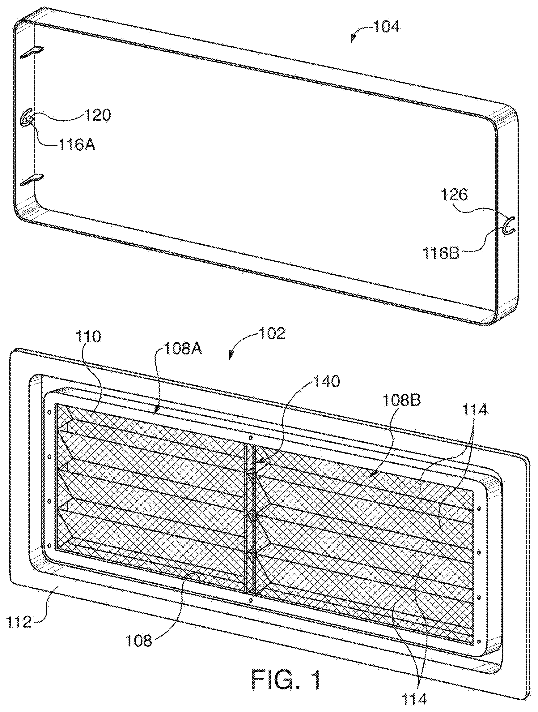
[0012] FIG. 1 is a rear perspective view of a combination of an air vent and a cover therefor, according to at least one aspect of the invention;
[0013] FIG. 2 is an exploded environmental front perspective view of the combination of FIG. 1;
[0014] FIG. 3 is an enlarged perspective detail view taken from the left of the lowermost component shown in FIG. 2;
[0015] FIG. 4 is a side cross sectional view of the center component shown in FIG. 2; and
[0016] FIG. 5 is an enlarged side cross sectional view of FIG. 4.
DETAILED DESCRIPTION
[0017] Referring first to FIGS. 1 and 2, according to at least one aspect of the invention, there is shown a combination 100 of an air vent 102 for passing air through an opening 10 of a wall 12 around an enclosed area, to facilitate ventilation, and a cover 104 for blocking air from passing through opening 10, wherein cover 104 is readily installable on and removable from air vent 102. Combination 100 may comprise air vent 102 including a central opening 108 for ventilation, a screen 110 fixed to air vent 102 and covering central opening 108, a planar peripheral flange 112 surrounding central opening 108. Peripheral flange 112 occupies a plane perpendicular to a direction of flow of air through central opening 108. False louvers 114 covering screen 110. False louvers 114 may be arranged to leave central opening 108 unobstructed for passage of air past screen 110.
[0018] Cover 104 may be dimensioned and configured to overlie central opening 108 in a deployed position and to block air flow through air vent 102 when cover 104 is installed. One of air vent 102 and cover 104 may include at least one integral deflectable tab 116 configured to engage by snap fit the other of air vent 102 and cover 104, and to releasably couple air vent 102 to cover 104.
[0019] Flow of air through central opening 108 is indicated as arrows A in FIG. 4.
[0020] Peripheral flange 112 provides a mounting member for mounting air vent 102 over opening 10. Fasteners such as stainless-steel nails (not shown) may be driven through peripheral flange 112 into wall 12. Alternatively, adhesive may be applied to peripheral flange 112 to bond air vent 102 to wall 12. Air vent 102 will then passively ventilate space behind wall 12 when cover 104 is not installed. The plane perpendicular to the direction 14 of flow of air alluded to above will be parallel to the outer surface of wall 12 when air vent 102 is mounted to wall 12, with direction 14 of air flow being perpendicular to the sides of wall 12 defining opening 10.
[0021] Louvers 114 may be left in an open position enabling air flow if louvers 114 are functional and pivotally coupled to air vent 102. In one implementation of combination 100, and as illustrated, louvers 114 are false louvers unadjustable relative to air vent 102.
[0022] One of air vent 102 and cover 104 includes at least one integral deflectable tab 116 configured to engage by snap fit the other of air vent 102 and cover 104 and to releasably couple air vent 102 to cover 104. In combination 100, the other of air vent 102 and cover 104 has at least one hole 118. The at least one deflectable tab 116 includes a projection 120 configured to enter and occupy the at least one hole 118 in the other of air vent 102 and cover 104 when the at least one deflectable tab 116 is not deflected, and to be released from at least one hole 118 when deflectable tab 116 is deflected. Each projection 120 frictionally engages one-hole 118A or 118B, and may or may not be audible when so engaging or disengaging from its respective hole 118A or 118B. This frictional connection is referred to herein as a snap fit.
[0023] Air vent 102 may have a right side 122 and a left side 124 (FIG. 2) when installed over opening 10 of wall 12. The at least one deflectable tab 116 may comprise a first tab 116A (FIG. 1) at the right side 122 of air vent 102 and a second tab 116B (FIG. 1) at left side 124 of air vent 102. The at least one hole 118 may comprise first hole 118A at right side 122 of air vent 102 and second hole 118B at left side 124 of air vent 102.
[0024] Unless otherwise indicated, the terms "first", "second", etc., are used herein merely as labels, and are not intended to impose ordinal, positional, or hierarchical requirements on the items to which these terms refer. Moreover, reference to, e.g., a "second" item does not either require or preclude the existence of, e.g., a "first" or lower-numbered item, and/or, e.g., a "third" or higher-numbered item.
[0025] Referring principally to FIG. 3 but also to FIGS. 1 and 2, first tab 116A and second tab 116 may each be defined on three sides (not called out by reference numerals) by a slot 126 formed in cover 104 and are attached to cover 104 at a living hinge 128 defined on a fourth side (not called out by reference numeral) of first or second tab 116A or 116B. Slot 126 may be U-shaped as shown and formed in a side wall 130 of cover 104.
[0026] Ordinarily, the term "living hinge" implies a construction wherein constituent material of the item bearing the living hinge is thinner at the hinge than at other portions of the item. That may or may not be the case with cover 104 (or with air vent 102, if it is desired to form first and second tabs 116A and 116B in air vent 102). It may be that the area represented by dashed line as living hinge 128 may be a portion of cover 104 (or air vent 102) undergoing bending when tab 116A or 116B deflects. In the illustrated embodiment, first tab 116A and second tab 116B are on cover 104, and first hole 118 and second hole 118 are in air vent 102.
[0027] As seen in greater scale in FIG. 3, cover 104 may comprise access opening 132 dimensioned and configured to enable a person (not shown) to insert a finger thereinto and impose pressure on air vent 102 in a direct ion releasing cover 104 from engagement with air vent 102. This may assist in releasing cover 104 from air vent 102.
[0028] Referring particularly to FIG. 4, air vent 102 may comprise a perimetric projection 134 perpendicular to peripheral flange 112 and surrounding central opening 108. First hole 118 and second hole 118 may be in the perimetric projection of the air vent. Perimetric projection 134 extends from peripheral flange 112 along a direction indicated by projection line 136 in FIG. 4. Peripheral flange 112 extends in a direction indicated by projection line 138. It will be seen that projection lines 136 and 138 are mutually perpendicular.
[0029] Perimetric projection 134 may be double walled and hollow in cross section along at least most of a length of perimetric projection 134. Hollow double walled configuration of perimetric projection 134 is illustrated in FIGS. 4 and 5. The length of perimetric projection 134 is best depicted in FIG. 2, wherein perimetric projection 134 is seen to take the form of a generally rectangular low wall projecting from flange 112 of air vent 102.
[0030] Turning again to FIG. 1, air vent 102 may further comprise a central wall 140 dividing central opening 108 into a right portion 108A and a left portion 108B. Central wall 140 is mostly seen in FIG. 1 as a planar member parallel to peripheral flange 112 but may include structure concealed in the view of FIG. 1 providing center support to louvers 114. Therefore, louvers 114 may be coupled to perimetric projection 134 at right side 122 of air vent 102, at left side 124 of air vent 102, and at central wall 140 of air vent 102.
[0031] False louvers 114 are coupled to perimetric projection 134 at a right side of air vent 102, at a left side of air vent 102, and at central wall 140 of air vent 102. Each false louver 114 may comprise a gusset 142 perpendicular to false louver 114 and spanning respective false louver 114 and the right side and the left side of air vent 102. Each gusset 142 seals an end of a respective false louver 114 against loss of air from air flow at false louver 114 through air vent 102 to lateral air flow not passing through air vent 102. It will be understood then that gussets 142 are continuously joined to false louvers 114 along their respective common abutting lengths and similarly, continuously joined to peripheral flange 112, to seal against loss of air flow.
[0032] Gussets 142 are called out in FIG. 4.
[0033] Cover 104 may be made substantially from one or more plastic materials by pressure molding. The plastic material may comprise ABS (acrylonitrile butadiene styrene) plastic material.
[0034] Cover 104 may thus be formed monolithically in a single molding. The selected constituent material has sufficient flexibility so that when components and walls of cover 104 are about one sixteenth of an inch thick, deflectable tabs 116 will bend sufficiently to enable performance as described herein, while being half an inch wide and one half to five eighths of an inch in length. Central wall 140 may comprise ribs or other structure and supports louvers 114 as well as dividing opening 108.
[0035] For the purposes of this application, pressure molding signifies that form is imparted to a constituent material by exerting either pressure above ambient pressures, thereby forcing the constituent material when in a fluent or flexible form into a mold or die, or alternatively, by subjecting the constituent material in the fluent or flexible form to vacuum, or pressures below ambient pressures.
[0036] Combination 100 may further comprise decorative surface texturing on air vent 102 and on cover 104. Such texturing may be limited to surfaces exposed to view when installed on wall 12.
[0037] For the purposes of this application, surface texturing signifies that there is a feature imparted to the surface intentionally formed in the surface in a repeating pattern. A repeating pattern signifies that there are at least three identical or substantially similar occurrences of the artistic element, each abutting at least one of the others or closely adjacent thereto without actual contact.
[0038] Examples of surface texturing include, by way of illustration but not limitation, simulation of natural wood grain; simulation of animal hair; simulation of animal skin, such as including simulated scales or simulated leather grain; a simulation of so-called wrinkle paint, which when cured forms irregular ridges in what would otherwise be a substantially planar surface; simulation of ball peen hammering of a metal surface, or dimpling; repeating geometric shapes separated from one another by a distance less than a minimum longitudinal, transverse, or diametric dimension of the geometric shape, where the greatest transverse or height dimension of a geometric shape is less than one inch; and combinations of these.
[0039] While the present invention has been described in connection with what is considered the most practical and preferred embodiment, it is to be understood that the present invention is not to be limited to the disclosed arrangements, but is intended to cover various arrangements which are included within the spirit and scope of the broadest possible interpretation of the appended claims so as to encompass all modifications and equivalent arrangements which are possible.
* * * * *
D00000
D00001
D00002
D00003
XML
uspto.report is an independent third-party trademark research tool that is not affiliated, endorsed, or sponsored by the United States Patent and Trademark Office (USPTO) or any other governmental organization. The information provided by uspto.report is based on publicly available data at the time of writing and is intended for informational purposes only.
While we strive to provide accurate and up-to-date information, we do not guarantee the accuracy, completeness, reliability, or suitability of the information displayed on this site. The use of this site is at your own risk. Any reliance you place on such information is therefore strictly at your own risk.
All official trademark data, including owner information, should be verified by visiting the official USPTO website at www.uspto.gov. This site is not intended to replace professional legal advice and should not be used as a substitute for consulting with a legal professional who is knowledgeable about trademark law.