Deployable Platforms
Banerjee; Robin ; et al.
U.S. patent application number 16/933113 was filed with the patent office on 2021-01-21 for deployable platforms. The applicant listed for this patent is NEXGEN COMPOSITES LLC. Invention is credited to Robin Banerjee, Michael S. Sheppard.
| Application Number | 20210017723 16/933113 |
| Document ID | / |
| Family ID | 1000005005978 |
| Filed Date | 2021-01-21 |


View All Diagrams
| United States Patent Application | 20210017723 |
| Kind Code | A1 |
| Banerjee; Robin ; et al. | January 21, 2021 |
DEPLOYABLE PLATFORMS
Abstract
A platform panel is disclosed. The panel includes a core having a top surface and a bottom surface. The core has a composite skin disposed on the top surface and the bottom surface of the core. Further, recessed pockets having a fastener port. Moreover, the panel includes a first hinge member disposed on a first side of the core, and a second hinge member disposed on an opposing side of the core in relation to the first hinge member.
| Inventors: | Banerjee; Robin; (Centerville, OH) ; Sheppard; Michael S.; (Centerville, OH) | ||||||||||
| Applicant: |
|
||||||||||
|---|---|---|---|---|---|---|---|---|---|---|---|
| Family ID: | 1000005005978 | ||||||||||
| Appl. No.: | 16/933113 | ||||||||||
| Filed: | July 20, 2020 |
Related U.S. Patent Documents
| Application Number | Filing Date | Patent Number | ||
|---|---|---|---|---|
| 62876353 | Jul 19, 2019 | |||
| Current U.S. Class: | 1/1 |
| Current CPC Class: | E01D 15/122 20130101; E01D 19/125 20130101; E01D 15/124 20130101 |
| International Class: | E01D 19/12 20060101 E01D019/12; E01D 15/12 20060101 E01D015/12 |
Claims
1. A platform panel comprising: a core having a top surface and a bottom surface; a composite skin disposed on the top surface and the bottom surface of the core; a recessed pocket disposed on the top surface of the core, wherein the recessed pocket comprises a fastener port; a first hinge member disposed on a first side of the core; and a second hinge member disposed on an opposing side of the core in relation to the first hinge member.
2. The panel of claim 1, wherein: the composite skin on the top surface of the core has a thickness greater than the composite skin on the bottom surface of the core.
3. The panel of claim 1, wherein: the composite skin on the top surface of the core has a non-uniform thickness.
4. The panel of claim 1 further comprising: a receiving port for attachment to an adjacent panel.
5. The panel of claim 1 further comprising: a rigid frame disposed around a periphery of the core.
6. The panel of claim 5, wherein: the rigid frame further comprises embedded hard points for mechanical attachments.
7. The panel of claim 1 further comprising: a positioner coupled to the bottom surface of the core.
8. The panel of claim 1, wherein: the first hinge member further comprises a spacer; and the second hinge member does not have a spacer.
9. The panel of claim 1, wherein: the first hinge member further comprises a cut-out portion.
10. The panel of claim 9, wherein the second hinge member further comprises a cut-out portion.
11. A panel comprising: a core having a top surface and a bottom surface; a composite skin disposed on the top surface and the bottom surface of the core; a connection edge coupled to the core, wherein the connection edge comprises a member that fastens to an adjacent panel; and a beveled edge that opposes the connection edge, wherein when in use, the beveled edge rests on a ground surface.
12. The panel of claim 11, wherein: the composite skin on the top surface of the core has a thickness greater than the composite skin on the bottom surface of the core.
13. The panel of claim 11 further comprising: the composite skin on the top surface of the core has a non-uniform thickness.
14. The panel of claim 11, wherein: the connection edge is selectively removable from the core.
15. The panel of claim 11, wherein: the member is a pin.
16. A deployable bridge assembly comprising: a first panel comprising: a first core having a top surface and a bottom surface; a composite skin disposed on the top surface and the bottom surface of the first core; a connection edge coupled to the core, wherein the connection edge comprises a member that fastens to an adjacent panel; and a beveled edge that opposes the connection edge, wherein when in use, the beveled edge rests on a surface; a second panel comprising: a second core having a top surface and a bottom surface; a composite skin disposed on the top surface and the bottom surface of the second core; a connection edge coupled to the second core, wherein the connection edge comprises a member that fastens to an adjacent panel; and a beveled edge that opposes the connection edge, wherein when in use, the beveled edge rests on a ground surface; a platform panel disposed between the first panel and the second panel, the platform panel comprising: a third core having a top surface and a bottom surface; a composite skin disposed on the top surface and the bottom surface of the third core; a recessed pocket disposed on the top surface of the core, wherein the recessed pocket comprises a fastener port; a first set of ports that receive the member from the first panel; and a second set of ports that receive the member from the second panel.
17. The deployable bridge assembly of claim 16, wherein: The first platform panel further comprises: a first hinge member disposed on a first side of the first platform panel, wherein the first hinge member comprises a first spacer; and a second hinge member disposed on an opposing side of the first platform panel in relation to the first hinge member, wherein the second hinge member does not have a spacer; further comprising: a second platform panel disposed between the first panel and the second panel, the second platform panel comprising: a third hinge member disposed on a first side of the second platform, wherein the third hinge member does not have a spacer; and a fourth hinge member disposed on an opposing side of the second platform panel in relation to the third hinge member, wherein the fourth hinge member comprises a second spacer; wherein when in use: the first hinge member is adjacent to the third hinge member; and the second hinge member is adjacent to the fourth hinge member, thereby positioning the first spacer on an opposing side of the bridge assembly in relation to the second spacer.
18. The deployable bridge assembly of claim 16, wherein: the first platform panel and/or the second platform panel further comprise a positioner.
19. The deployable bridge assembly of claim 16, wherein: the bridge assembly couples to a spanning member that spans a spatial gap.
20. The deployable bridge assembly of claim 16, wherein: wherein the composite skin on the top surface of the first core has a thickness greater than the composite skin on the bottom surface of the first core; and wherein the composite skin on the top surface of the second core has a thickness greater than the composite skin on the bottom surface of the second core.
Description
CROSS REFERENCE TO RELATED APPLICATIONS
[0001] This application claims the benefit of U.S. Provisional Patent Application Ser. No. 62/876,353. filed Jul. 19, 2019, entitled DEPLOYABLE PLATFORMS, the disclosure of which is hereby incorporated by reference.
BACKGROUND
[0002] Various aspects of the present disclosure relate generally to a deployable platform, and more specifically to a bridge assembly made from the deployable platforms.
[0003] Temporary building structures are used to serve one or more functions during a limited time period. For example, in military operations, temporary building structures are used to provide dwellings for soldiers, act as a barrier against inclement weather, and/or provide a command center for forward operating bases. In other instances, temporary building structures can be used to traverse terrain.
BRIEF SUMMARY
[0004] According to aspects of the present disclosure, a platform panel is disclosed. The panel includes a core having a top surface and a bottom surface. The core has a composite skin disposed on the top surface and the bottom surface of the core. Further, recessed pockets having a fastener port. Moreover, the panel includes a first hinge member disposed on a first side of the core, and a second hinge member disposed on an opposing side of the core in relation to the first hinge member.
[0005] According to additional aspects of the present disclosure, a platform panel is disclosed. The panel includes a core having a top surface and a bottom surface. The core has a composite skin disposed on the top surface and the bottom surface of the core. Further, the panel also has a positioner disposed on the bottom surface of the core. Moreover, the panel includes a first hinge member disposed on a first side of the core, and a second hinge member disposed on an opposing side of the core in relation to the first hinge member.
[0006] According to further aspects of the present disclosure, a ramp panel is disclosed. The ramp panel has a core having a top surface and a bottom surface. The ramp panel includes a composite skin disposed on the top surface and the bottom surface of the core. The ramp panel also includes a connection edge having members that selectively fasten to the core, and a beveled edge that opposes the connection edge, wherein when in use, the beveled edge rests on a ground surface.
[0007] According to yet further aspects of the present disclosure, a deployable bridge deck assembly is disclosed. The bridge deck assembly incorporates aspects of the platform panel and the ramp panel. The bridge deck assembly has two ramp panels, with each ramp panel having a core, a composite skin, and a ramp attachment as described herein. Moreover, the bridge deck assembly has a platform panel disposed between the two ramp panels, the platform panel having a core, a composite skin a positioner, and a first and second hinge member as described herein.
BRIEF DESCRIPTION OF THE SEVERAL VIEWS OF THE DRAWINGS
[0008] FIG. 1 is an embodiment of a platform panel according to various aspects of the present disclosure as described in greater detail herein;
[0009] FIG. 2 is an embodiment of two platform panels coupled together by a hinge member according to various aspects of the present disclosure as described in greater detail herein;
[0010] FIG. 3A is a bottom-up view of an example platform panel according to various aspects of the present disclosure as described in greater detail herein;
[0011] FIG. 3B is another bottom-up view of an example platform panel according to various aspects of the present disclosure as described in greater detail herein;
[0012] FIG. 3C is yet another bottom-up view of an example platform panel according to various aspects of the present disclosure as described in greater detail herein;
[0013] FIG. 4 illustrates a series of platform panels according to various aspects of the present disclosure as described in greater detail herein;
[0014] FIG. 5 is an embodiment of a ramp panel according to various aspects of the present disclosure as described in greater detail herein;
[0015] FIG. 6 is an embodiment of a connection edge according to various aspects of the present disclosure as described in greater detail herein;
[0016] FIG. 7 is an embodiment of a bridge deck assembly according to various aspects of the present disclosure as described in greater detail herein;
[0017] FIG. 8 is another embodiment of a bridge deck assembly according to various aspects of the present disclosure as described in greater detail herein'
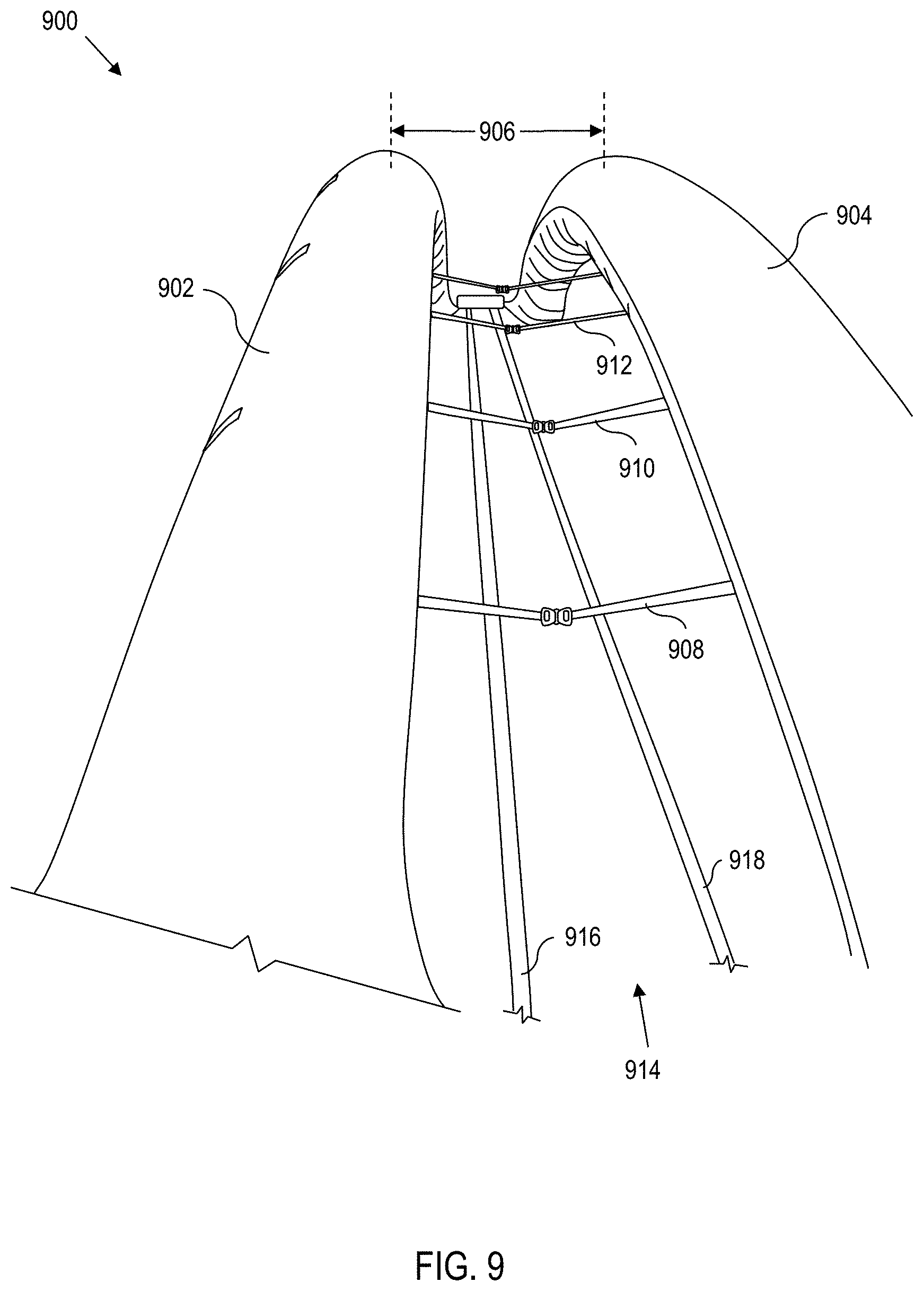
[0018] FIG. 9 illustrates an inflatable bridging member, according to various aspects of the present disclosure;
[0019] FIG. 10 illustrates the inflatable bridging member with panels coupled to the bridging member, according to various aspects of the present disclosure; and
[0020] FIG. 11 illustrates a coupling mechanism to couple the inflatable bridging member to the panels, according to various aspects of the present disclosure.
DETAILED DESCRIPTION
[0021] Bridges and similar mechanisms are commonly used to cross gaps or traverse over undesirable terrain (e.g., rivers, cliffs, etc.). While effective, bridges can take considerable time, planning, and resources to construct. In instances where a bridge is anticipated to be used for many years, expending the time and resources toward constructing the bridge is usually justifiable.
[0022] However, in some instances such as military operations, a bridge may see limited use (e.g., the bridge is used a few times to move a forward operating base from one area to another), or multiple bridges may be needed during the course of the military operation. In such instances, expending time, planning, and resources to build a permanent bridge becomes inefficient and/or undesirable. Moreover, if the military operation is in hostile territory, there is an added risk of personnel being attacked while constructing the bridge.
[0023] Accordingly, aspects of the present disclosure are directed toward a lightweight, rapidly-deployable platform solution that can serve as a bridge or deck for gap crossing. In various implementations, the platform panels include integrated hardpoints and recessed pockets for attachment to underlying structures. Moreover, in multiple configurations, the platform panels can fold or stack "accordion style" to stow and deploy for easier transport as described in greater detail herein.
[0024] Platform Panel
[0025] Referring to the figures, and particularly FIG. 1, a platform panel 100 is disclosed. The platform panel 100 comprises a core 102 having a top surface 104 and a bottom surface 106.
[0026] The core 102 may comprise a single material or a combination of materials such as carbon fiber, fiberglass, fiberglass reinforced resin, foam (e.g., polymer foam), honeycomb material, polyethelene teraphalate (PET), metals, wood, stiffening materials, etc. Moreover, the core 102 may vary in thickness depending on user needs and materials that are used. Preferably, materials that have a high strength to weight ratio (i.e., high strength and low weight), are utilized for the core 102. Materials such as aluminum, while functional, may be heavier than desired for users that are moving multiple platform panels with frequency.
[0027] Moreover, the platform panel 100 comprises a composite skin disposed on the top surface 104 and the bottom surface 106 of the core 102. In FIG. 1, the composite skin completely covers the top surface 104 of the core 102. The composite skin can be made from a variety of materials such as carbon fiber, fiberglass, fiberglass reinforced resin, etcetera.
[0028] In various embodiments, the composite skin on the top surface 104 of the core 102 has a thickness greater than the composite skin on the bottom surface 106 of the core 102 to account for compressive forces and other external forces such as vehicles and/or personnel that traverse over the platform panel 100. Moreover, in addition to (or alternative to) the composite skin varying in thickness, the composite skin may also vary in uniformity.
[0029] In multiple examples, the composite skin has non-uniform thickness to increase surface area or provide more traction (or "grip") for vehicles and/or personnel traversing over the platform panel 100. For instance, the composite skin may form undulations. In other implementations, grip tape or similar mechanisms can be added to the top surface 104 of the core 102 for enhanced traction. Moreover, the skin on a bottom of the panel may be nonuniform.
[0030] In various embodiments, the platform panel 100 further comprises a rigid frame 108 disposed around a periphery of the core 102 as shown in FIG. 1. The rigid frame 108 provides increased protection and durability for the core 102. The rigid frame 108 can be made from various polymers (e.g., plastics, resins such as polyethelene teraphalate, etc.), metals (e.g., aluminum), fiber reinforced foam, carbon fiber reinforcement in a polymer matrix, or a combination thereof.
[0031] The rigid frame 108 may further comprise various hardpoints 110 that provide numerous functions. For example, the hardpoints 110 may be used to move or maneuver the platform panel 100. In addition, the hardpoints can be used to serve as an anchor or tie-down point for mechanical attachments to secure the platform panel 100 to another structure (e.g., feeding rope or webbing through the hardpoint 110 to connect to a cross-beam).
[0032] In this regard, the platform panel 100 may also utilize a recessed pocket 112 disposed on the top surface 104 of the core 102, which includes one or more fastener ports 114 disposed within the recessed pocket 112. Examples of fasteners that are suitable for use in conjunction with the fastener port include, but are not limited to clamps, over-center latches, J-hooks, locks (e.g., twist locks, cam locks, lever locks, etc.), ratchets, etc.
[0033] The recessed pocket 112 provides numerous benefits. For instance, the recessed pocket 112 allows a user of the platform panel 100 to fasten the platform panel 100 to an underlying structure (e.g., support structures, suspension structures (e.g., I-beam, rails, etc.), etc.) without the fastener sticking out above the top surface 104.
[0034] Having the fastener disposed within the recessed pocket 112 minimizes, or even eliminates, the possibility of a fastener creating a road hazard that may damage vehicles passing over the platform panel. Having the fastener disposed within the recessed pocket 112 also allows users to deploy or lay an additional layer or surface (e.g., sheet metal, asphalt, etc.) without being obstructed by the fastener.
[0035] The recessed pocket 112 also provides a larger area for more complex and/or larger fasteners (or coupling members) to be used without being a road hazard as described herein.
[0036] In addition, the recessed pocket 112 and fastening port 114 also allows users to re-use fasteners without damaging the platform panel 100. In existing solutions, fasteners such as screws, nails, rivets, etc. are punched through platforms to secure the platform to the underlying structure, thus causing damage to the platform.
[0037] Conversely, the recessed pocket 112 and fastening port 114 allow users to use non-damaging fasteners and couplers (e.g., ratchets, clamps, etc.) without damaging the platform panel 100, thus increasing longevity of the platform panel as well as minimizing time spent deployment/stowing the platform panel 100.
[0038] FIG. 1 also illustrates a first hinge member 116 and a second hinge member 118 disposed on opposing sides of the platform panel 100. In various embodiments, the first hinge member 116 comprises a spacer, whereas the second hinge member 118 does not have a spacer as described in greater detail herein.
[0039] In multiple implementations, the platform panel 100 further comprises a receiving port 120 for attachment to an adjacent panel (e.g., another platform panel, or a ramp panel as described in greater detail herein). In multiple implementations, the receiving port 120 is a hollow hardpoint (similar to the hardpoints in the frame discussed above). In some such implementations, the hollow hardpoint allows a fastener (such as a solid pin) to have a small degree of freedom (or "play") to allow panels into interconnect at various angles.
[0040] In multiple embodiments, more than one receiving port 120 is used as indicated by the boxes in dashed lines. In this regard, not all platform panels disclosed herein utilize a receiving port 120. In various embodiments, only platform panels that couple to ramp panels utilize a receiving port 120 as described in greater detail herein.
[0041] FIG. 2 illustrates an example of two platform panels 100a and 100b (from left to right respectively) that are coupled together by a first hinge member 116 and a second hinge member 118. Here, platform panel 100a includes a spacer 122 disposed between the first hinge member 116 and the platform panel 100a.
[0042] Conversely, the platform 100b does not have a spacer between the second hinge member 118 and the platform 100b. The spacer 122 compensates for an offset "O" created by coupling the platform panel 100a to the platform panel 100b via the first hinge member 116 and the second hinge member 118 as shown in FIG. 2. Positionally, the spacers 122 alternate between opposing sides of a platform panel (e.g., platform panel 100a) on each subsequent platform panel (e.g., left side of panel 100a has a spacer, left side of platform panel 100b, which is adjacent to platform panel 100a, does not have a spacer, etc.).
[0043] Without the spacer 122 compensating for the offset "0", a series of platform panels (e.g., 100a, 100b, 100c, . . . 100n) would zip-zag or stagger from one another when deployed (i.e., the series of panels would not deploy in a straight line), which can lead to other complications. While the hinge members 116 and 118 can utilize various geometries, the geometry shown in FIGS. 1 and 2 allows platform panels to rapidly stow and deploy as described in greater detail herein.
[0044] In various embodiments, the first hinge member 116 and/or the second hinge member 118 further comprise a cut-out portion 124 (e.g., flutes, channels, etc.) for weight reduction.
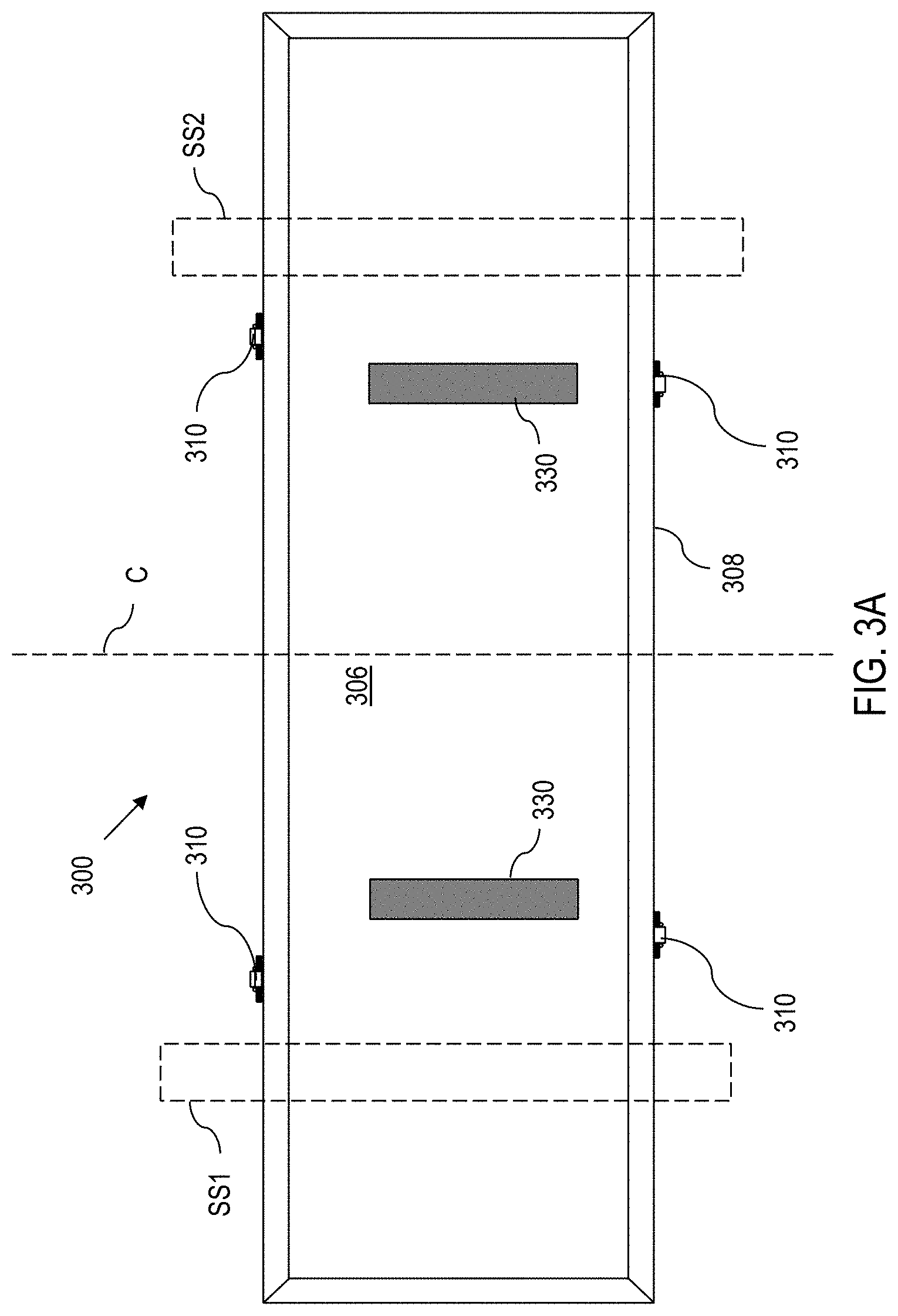
[0045] Now referring to FIG. 3A, a bottom-up view of an example platform panel 300 is illustrated. The platform panel 300 can either be a stand-alone embodiment, or a variant of the platform panel 100. Therefore, embodiments and variations may be shared. As such, like features and elements share like numbers, except that features and elements of FIG. 3A are numbered 200 higher (e.g., hardpoint 310 is analogous to hardpoint 110, unless stated otherwise).
[0046] The platform panel 300 comprises a positioner 330 coupled to the bottom surface 306 of the core 302. The positioner 330 acts as a barrier that prevents structures from encroaching a center line "C" of the platform panel 300.
[0047] For instance, if the platform panel 300 is deployed over a first support structure "SS1" and a second support structure "SS2", both of which are capable of lateral movement toward the center line "C", the positioner 330 may prevent the first support structure "SS1" and the second support structure "SS2" from getting too close to the center line "C", which may cause instability. Moreover, the positioner 330 also aids in maintaining the platform panel 300 in a desired orientation and further stabilizes the platform panel 300.
[0048] In embodiments associated with FIG. 3A, the positioner 330 acts as a guide or "bumper" that keeps the platform panel 300 within the support structures SS1 and SS2.
[0049] In various embodiments, the positioner 330 can be locked in place (e.g., by a nylon lock nut) when stowed, and selectively released (e.g., by a quick-release pin). In various embodiments, the positioner 330 the positioner hingedly swings (e.g., via hinges) toward an outside edge of the core 302.
[0050] In yet further embodiments, the positioner 330 can be tethered to the platform panel 300 so that the positioner 330 does not exceed a predefined rotation or travel distance (e.g., positioner is tethered to panel to prevent over-rotation beyond 90.degree.).
[0051] Now referring to FIG. 3B, a bottom-up view of another example platform panel 300 is illustrated. The platform panel 300 can either be a stand-alone embodiment, or a variant of the platform panel 100. Therefore, embodiments and variations may be shared. As such, like features and elements share like numbers, except that features and elements of FIG. 3B are numbered 200 higher (e.g., hardpoint 310 is analogous to hardpoint 110, unless stated otherwise).
[0052] In FIG. 3B, a positioner 340 is disposed on the bottom surface 306 of the platform panel 300. In various embodiments, the positioner 340 guides the platform panel 300 along SS1 and SS2. In multiple implementations, the positioner 340 is an "L" shape, or a hook shape that goes under or around SS1 and SS2. In other implementations, the positioners 340 act as bumpers that butt against SS1 and SS2.
[0053] Now referring to FIG. 3C, a bottom-up view of yet another example platform panel 300 is illustrated. The platform panel 300 can either be a stand-alone embodiment, or a variant of the platform panel 100. Therefore, embodiments and variations may be shared. As such, like features and elements share like numbers, except that features and elements of FIG. 3C are numbered 200 higher (e.g., hardpoint 310 is analogous to hardpoint 110, unless stated otherwise).
[0054] FIG. 3C briefly illustrates an interaction between support structures (e.g., SS1 and SS2) and the fastener ports 314. Here, a re-usable fastener 350 (e.g., ratchet, or clamp) is fed through the fastener port 314 and engages SS1 and SS2. When a user needs to stow or remove the platform panel 300, the user can simply disengage the re-usable fastener 350 and pull it back through the fastener port 314.
[0055] In FIG. 4, a series of platform panels 400a, 400b, 400c, 400d, 400e, and 400f is illustrated in a partially deployed state. The disclosures with respect to FIG. 4 can either be a stand-alone embodiment, or a variant of any platform panel disclosed herein. Therefore, embodiments and variations may be shared across apparatuses.
[0056] As the series of platform panels begin deployment, subsequent platform panels, which are connected via hinge members (see e.g., 114 and 166 in FIG. 1), begin deployment as well. In FIG. 4, deployment begins with platform panel 400a (e.g., by a user that uses a tether looped through hardpoint 410 (see hardpoint 110 in FIG. 1 or hardpoint 310 in FIG. 3) as indicated by the solid arrow. As deployment continues, platform panel 100b follows after platform 100a, platform panel 400c follows platform panel 400b, and so on.
[0057] Reference numbers 406a and 406b, which are bottom surfaces of the platform panel 100a and 100b respectively, are shown for context.
[0058] Correspondingly, the series of platform panels can be stowed by reversing deployment, which results in a compact or stowed configuration illustrated by platform panels 400c, 400d, 400e, and 400f. In various embodiments, the series of platform panels can be retracted or stowed by using a winch or ratchet that connections to one or more hardpoints (e.g., 410a). While each panel within the series of panels is illustrated with hardpoints, in practice, hardpoints may be limited to specific panels (e.g., every other panel, patterned (every other adjacent panel has hardpoints that are adjacent to one another), etc.).
[0059] The stowed configuration illustrated in FIG. 4 has numerous advantages. For instance, the stowed configuration has a reduced physical footprint (i.e., takes up less overall space). Moreover, the stowed configuration allows each platform panel within the series of platform panels to remain coupled together, thus reducing time and labor costs when deploying, stowing, and transporting the series of platform panels.
[0060] In an alternative configuration, the series of platform panels can be deployed or "rolled" off of a barrel or spool. In another alternative configuration, the series of platform panels slide or telescope to deploy. In multiple implementations, deployment of the series of platform panels is done autonomously.
[0061] Aspects of the present disclosure also contemplate integrating a truss or railing system that deploys with the series of platform panels.
[0062] Ramp Panel
[0063] In addition to platform panels as disclosed herein, aspects of the present disclosure include one or more ramp panels that serve as transitions between a ground surface and a corresponding platform panel.
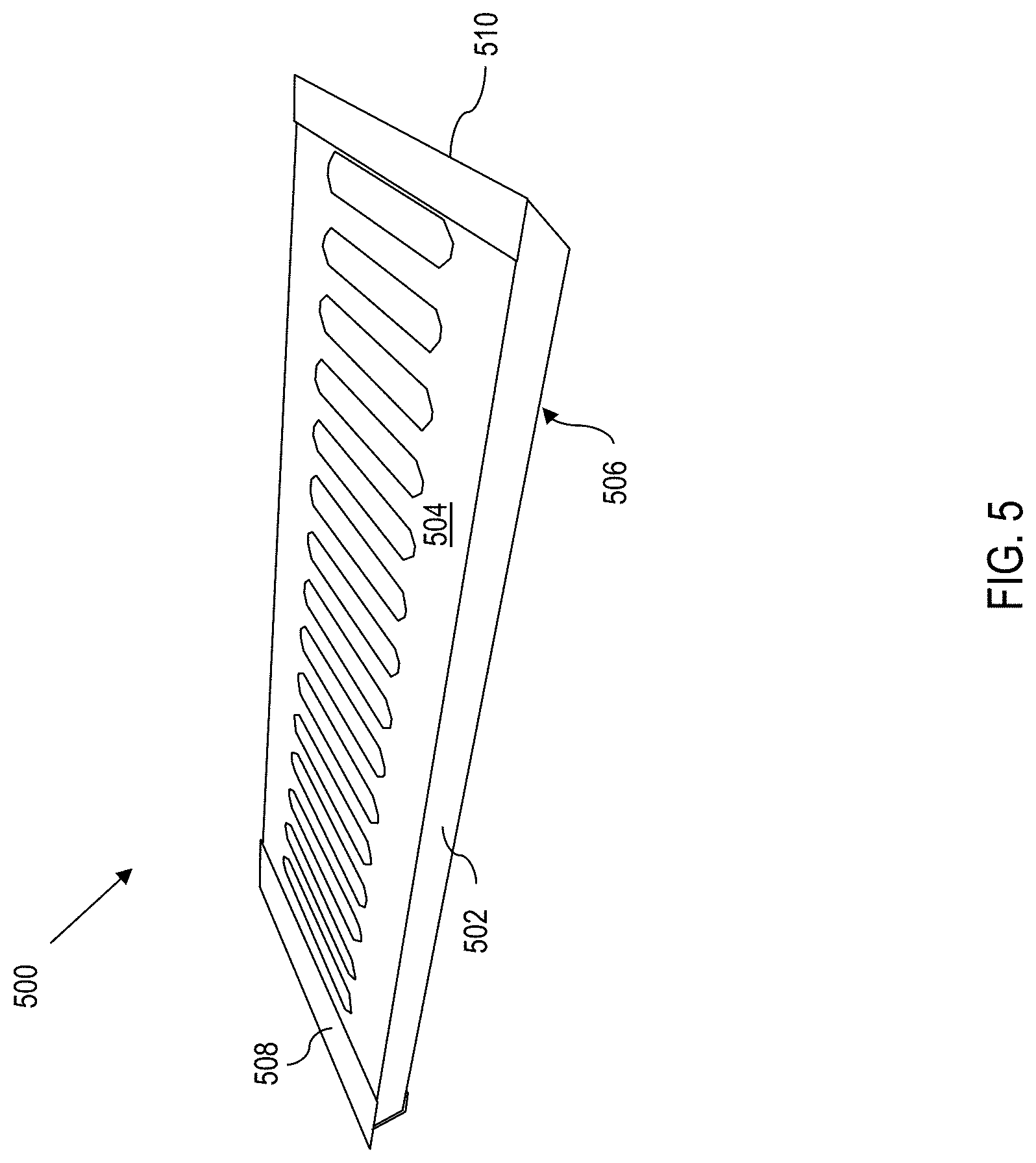
[0064] Now referring to FIG. 5, a ramp panel 500 is illustrated. The ramp panel 500 comprises a core 502 having a top surface 504 and a bottom surface 506. Moreover, the ramp panel 500 comprises a composite skin disposed on the top surface 504 and the bottom surface 506 of the core 502.
[0065] In this regard, the core 502 and composite skin of the ramp panel 500 are analogous to cores and composite skins as described herein (e.g., core 102 in FIG. 1). However, in various embodiments, the core 502 of the ramp panel 500 has a different composition or ratio of materials to account for differences in function when compared to a platform panel. For example, in various embodiments, the composite skin on the top surface 504 of the core 502 has a thickness greater than the composite skin on the bottom surface 506 of the core 502.
[0066] In other instances, the core 502 of the ramp panel 500 may have a greater thickness than that of the platform panel. Moreover, the core 502 of the ramp panel 500 may use compositional materials at higher densities, thus making the core 502 more stiff and/or rigid. In yet another instance, the core 502 may be constructed so that the core 502 bends under pressure, as opposed to compressing under pressure as is the case with some platform panels described herein (i.e., bending action vs compressive action).
[0067] Further, the ramp panel 500 comprises a connection edge 508 coupled to the core 502, wherein the connection edge 508 comprises a member that fastens to an adjacent panel as described in greater detail herein. In multiple embodiments, the member is an extruded pin.
[0068] Yet further, the ramp panel 500 comprises a beveled edge 510 that opposes the connection edge 508, wherein when in use, the beveled edge 510 rests on a ground surface.
[0069] In multiple examples, the composite skin has non-uniform thickness to increase surface area or to provide more traction (or "grip") for vehicles and/or personnel traversing over the ramp panel 500. For instance, the composite skin may form undulations. In other implementations, grip tape or similar mechanisms can be added to the top surface 504 of the core 502 for enhanced traction.
[0070] Now referring to FIG. 6, a close-up view of the connection edge 508 of the ramp panel 500 is illustrated. Here, the connection edge 508 comprises two members 512 that fasten to adjacent panels (e.g., the receiving port 120 of the platform panel 100 in FIG. 1). While the members 512 are shown as two pins, in practical application more or fewer pins could be used, or a different type of fastener may be used altogether. In multiple embodiments, the connection edge 508 is selectively removable from the core 502, which allows users to swap out one type of fastening member (e.g., the extruded pins) for another as described in greater detail herein. For example, the two pins can be swapped for hooks, threaded bolts, etc.
[0071] One advantage of a removable (or swappable) connections edge 508 is that the ramp panel 500 can be adapted to accommodate various ground angles that a user may encounter. Moreover, different fasteners are better suited for more demanding loads. Thus, a swappable connection edge 508 that uses different fasteners may be beneficial.
[0072] In FIG. 6, screws/rivets 514 are used to fasten the connection edge 508 to the core 502, but virtually any type of fastener would suffice.
[0073] Bridge Deck Assembly
[0074] FIG. 7 illustrates an example embodiment of a bridge deck assembly 700 (or "bridge assembly 700" for shorthand). The bridge assembly 700 may utilize one or more variations of the platform panels and ramp panels as described herein. Accordingly, the bridge assembly 700 may incorporate embodiments and disclosures of ramp panels and platform panels herein.
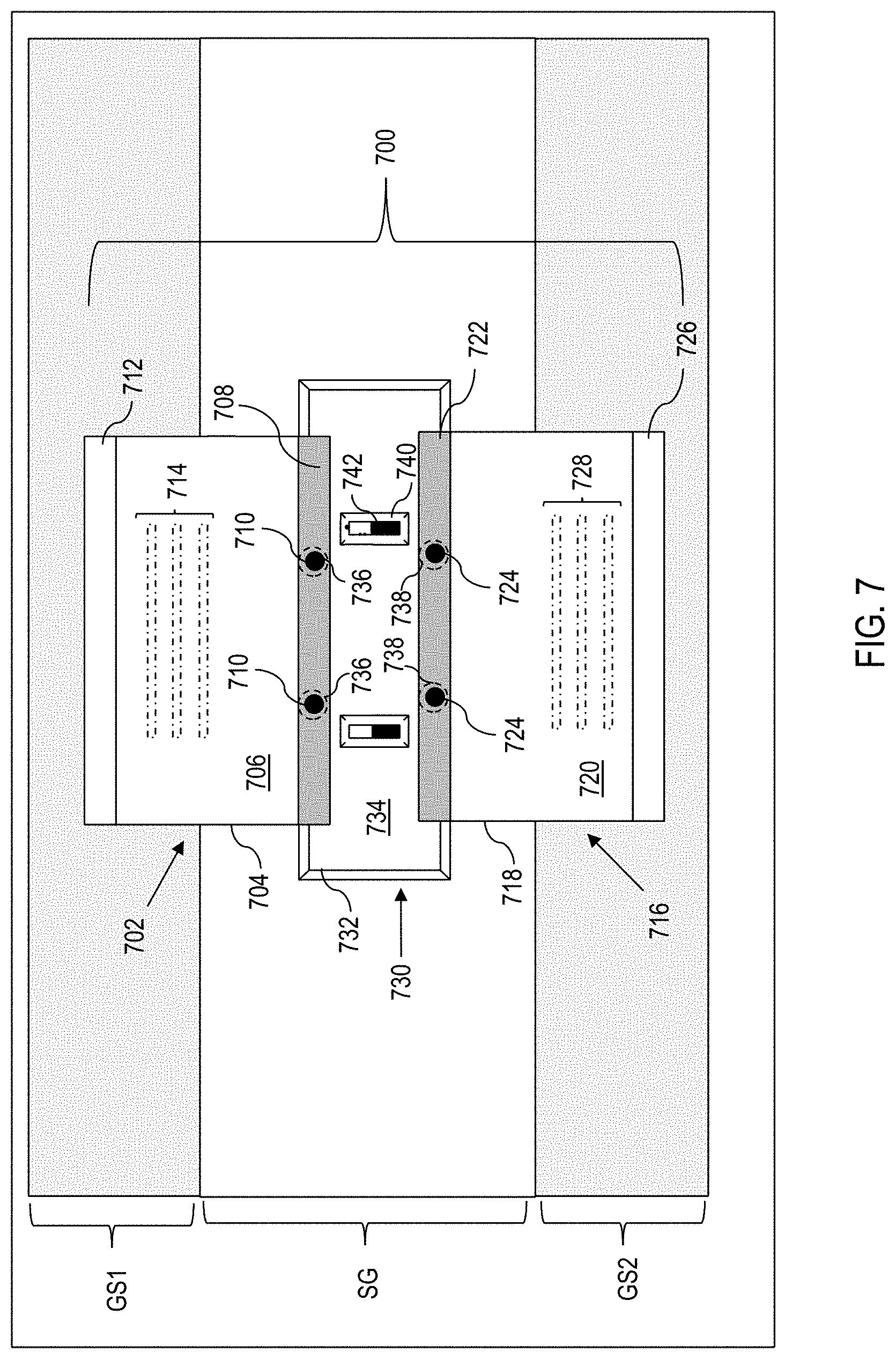
[0075] In FIG. 7, a bridge assembly 700 spans from one ground surface "GS1" to another ground surface "GS2" over a spatial gap "SG". The bridge assembly 700 comprises a first ramp panel 702. The first ramp panel 702 comprises a first core 704 having a top surface 706 and a bottom surface (obscured by view). The first ramp panel 702 further comprises a composite skin disposed on the top surface 706 and the bottom surface of the first core 704. In various embodiments, the composite skin on the top surface 706 of the first core 704 has a thickness greater than the composite skin on the bottom surface of the first core 704.
[0076] Moreover, the first ramp panel comprises a connection edge 708 coupled to the core 704, wherein the connection edge 708 comprises members 710 (see. e.g., fasteners 512 in FIG. 5) that fasten to an adjacent panel.
[0077] Yet further, the first ramp panel 702 comprises a beveled edge 712 that opposes the connection edge 708, wherein when in use, the beveled edge 712 rests on a ground surface (e.g., GS1). In various embodiments, the first ramp panel 702 further comprises a first grip member 714 (e.g., grip tape) or a similar mechanism to increase traction on the top surface 706 of the first core 704.
[0078] The bridge assembly 700 further comprises a second ramp panel 716. The second ramp panel 716 is analogous to the first ramp panel 702. In this regard, the second ramp panel 716 comprises a second core 718 having a top surface 720 and a bottom surface (obscured by view). The second ramp panel 716 further comprises a composite skin disposed on the top surface 720 and the bottom surface of the second core 718. In various embodiments, the composite skin on the top surface 720 of the second core 718 has a thickness greater than the composite skin on the bottom surface of the second core 718.
[0079] Moreover, the second ramp panel 716 comprises a connection edge 722 coupled to the second core 718, wherein the connection edge 722 comprises members 724 that fasten to an adjacent panel. In addition, the second ramp panel 716 comprises a beveled edge 726 that opposes the connection edge 722, wherein when in use, the beveled edge 726 rests on a ground surface (e.g., GS2). In various embodiments, the second ramp panel 716 further comprises a second grip member 728 (e.g., grip tape) or a similar mechanism to increase traction on the top surface 720 of the second ramp panel 716.
[0080] The bridge assembly 700 also comprises a platform panel 730 disposed between the first ramp panel 702 and the second ramp panel 716. The platform panel 730 comprises a third core 732 having a top surface 734 and a bottom surface (obscured by view), and a composite skin disposed on the top surface 734 and the bottom surface of the third core 732.
[0081] Moreover, the platform panel 730 comprises a positioner (obscured by view, but is analogous to positioner 330 in FIG. 3) coupled to the bottom surface of the third core 732.
[0082] Yet further, the platform panel 730 comprises a first set of ports 736 that receive the members 710 from the first ramp panel 702. In addition, the platform panel 730 comprises a second set of ports 738 that receive the members 724 from the second ramp panel 716. While the first set of ports 736 and the second set of ports 738 are illustrated in pairs, in practical application the first set of ports 736 and/or the second set of ports 738 may be implemented as a single port, three ports, slots, or any other suitable coupler, fastener, port, etc.
[0083] In various embodiments, the platform panel 730 further comprises a recessed pocket 740 disposed on the top surface 734 of the third core 732, and a fastening port 742 disposed within the recessed pocket 740.
[0084] Aspects of the present disclosure also contemplate embodiments of a bridge assembly that comprise two or more platform panels as illustrated in FIG. 8. The disclosures herein with respect to FIG. 8 can either be a stand-alone embodiment, or a variant of the bridge assembly 700 disclosed herein. As such, like features and elements share like numbers, except that features and elements of FIG. 8 are numbered 100 higher. Therefore, embodiments and variations may be shared.
[0085] In FIG. 8, the platform panel 730 (hereinafter "first platform panel") further comprises a first hinge member 744 disposed on a first side of the first platform panel 730, wherein the first hinge member 744 comprises a first spacer 746. Moreover, the platform panel 730 further comprises a second hinge member 748 disposed on an opposing side of the first platform panel 730 in relation to the first hinge member 744, wherein the second hinge member 748 does not have a spacer.
[0086] In addition, the bridge assembly 700 comprises a second platform panel 750 disposed between the first ramp panel 702 and the second ramp panel 716. The second platform panel 750 is analogous to the first platform panel 730, except that hinges disposed on the second platform panel 750 oppose hinge members of the first platform panel 730 as described herein.
[0087] In this regard, the second platform panel 750 comprises a third hinge member 752 disposed on a first side of the second platform 750, wherein the third hinge 752 member does not have a spacer. In addition, the second platform panel comprises a fourth hinge member 754 disposed on an opposing side of the second platform panel 750 in relation to the third hinge member 752, wherein the fourth hinge member 754 comprises a second spacer 756.
[0088] When in use, the first hinge member 744 is adjacent to the third hinge member 752, and the second hinge member 748 is adjacent to the fourth hinge member 754, thereby positioning the first spacer 746 on an opposing side of the bridge assembly 700 in relation to the second spacer 756.
[0089] In various embodiments, the second platform panel 750 further comprises a second positioner (obscured by view, but see e.g., positioner 330 in FIG. 3). All remaining reference numbers and markers are shown for context. Reference numbers that were shown in FIG. 7 that are not present in FIG. 8 were omitted for visual clarity unless stated otherwise.
[0090] The bridge deck assembly 700 in FIGS. 7 and 8 represent just a few of many possible configurations. For example, the bridge assembly 700 may comprise three or more panels. In various implementations, the ramp panels (e.g., 702 and 716) may be divided into two or more sub panels that can be laterally adjusted to accommodate a predefined width of a vehicle or personnel crossing over the bridge assembly 700 as shown in FIG. 8. Ramp panel 702 has been divided into 702a and 702b and ramp panel 716 has been divided into 716a and 716b. The remaining reference numbers (e.g., 710a and 710b) are shown for context.
[0091] Depending on material composition and an amount of platform panels used, various embodiments of the bridge assembly 700 can support vehicles up to 4,600 pounds (.about.20,865 kg) over a distance of 36 feet (11 meters), while the bridge assembly 700 itself weighs less than 600 pounds (.about.272 kg).
[0092] While the bridge assembly 700 in FIGS. 7 and 8 is shown in isolation when deployed over the spatial gap ("SG"), aspects of the present disclosure also contemplate use of the bridge assembly with a spanning member or support structure (see. SS1 and SS2 in FIG. 3). For example, the bridge assembly 700 can be deployed over and/or coupled to air beams, steel support beams, wooden support beams, matted on ground, a scissor lift, a cable support, or a combination thereof.
[0093] Bridge Assembly
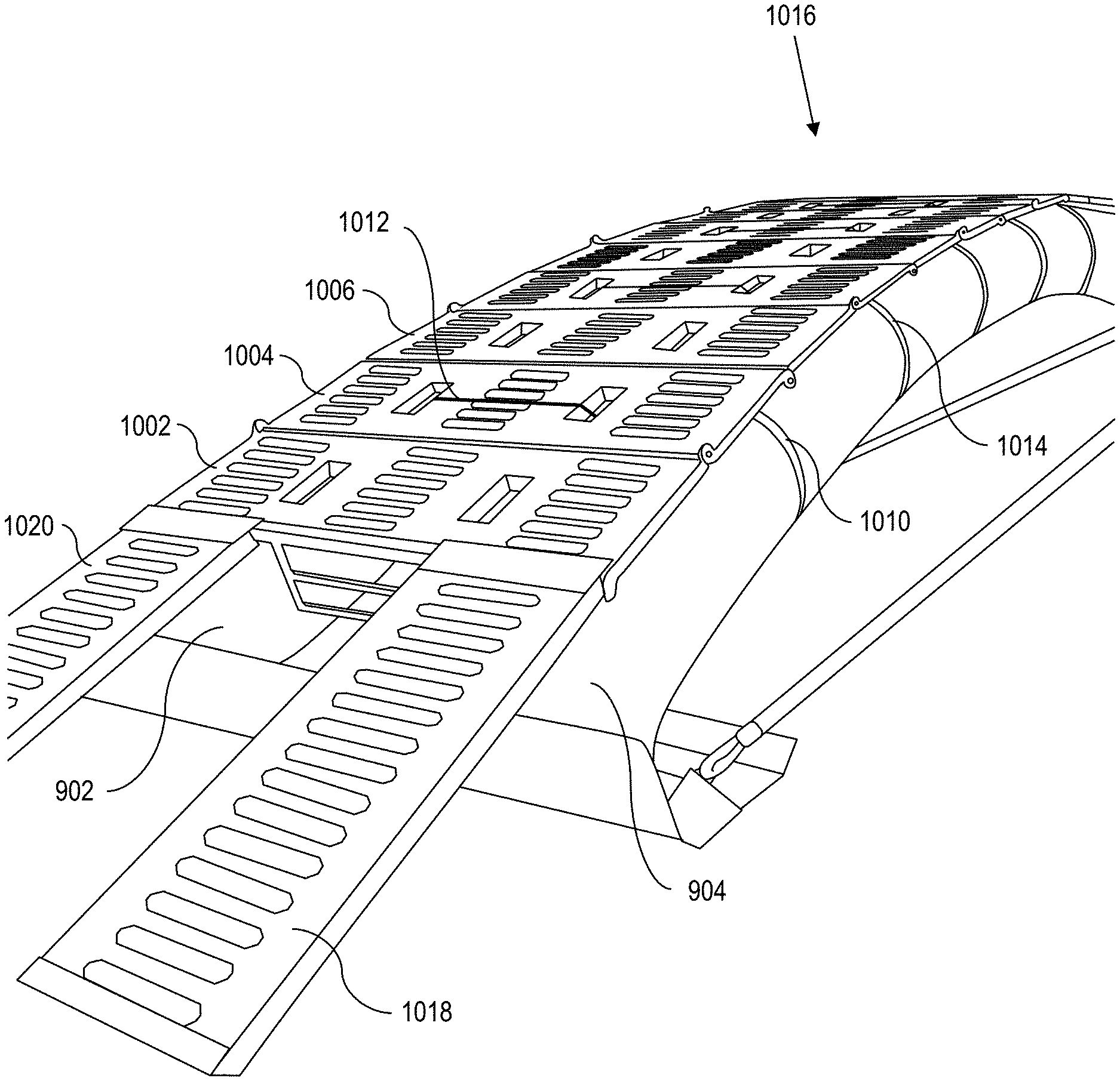
[0094] FIGS. 9-11 illustrate a bridging assembly. Turning now to FIG. 9, an inflatable bridging structure 900 without any panels coupled to it is shown. In the embodiment of FIG. 9, a first spanning member 902 and a second spanning member 904 are inflatable rails that can span a longer distance than panels alone. The first spanning member 902 and the second spanning member 904 maintain a desired distance 906 from each other (within an acceptable tolerance) by using separators 908, 910, 912 to ensure that the spanning members 902, 904 do not separate by more than the desired distance. The desired distance is based on panels, described above, that will be coupled to the spanning members to create the full bridging assembly as shown in FIG. 10.
[0095] With continued reference to FIG. 9, a retaining mechanism 914 that spans from one end of the bridging assembly to the other end of the bridging assembly 900 ensures that the spanning members 902, 904 are arched to provide support for a load on the bridging assembly 900 when the bridging assembly 900 is deployed. In the embodiment of FIG. 9, the retaining mechanism 914 comprises two runners (e.g., cables, straps, etc.) 916, 918; however, any retaining mechanism 914 will suffice. In general, the retaining mechanism 914 should be shorter than the spanning members 902, 904 to cause the spanning members 902, 904 to arch. While the spanning members are shown as inflatable in the embodiment of FIG. 1, the spanning members may be beams of metal, wood, concrete, composite, or a combination thereof.
[0096] Turning now to FIG. 10, the bridging assembly 900 of FIG. 9 is shown with panels described above coupled to the bridging assembly. In the embodiment shown, several deck panels 1002, 1004, 1006 are coupled to the spanning members 902, 904 via straps 1010, 1012, 1014 to provide a load-bearing surface 1016. Further, ramp panels 1018, 1020 are coupled to a first panel 1002 of the deck panels (as discussed in reference to FIG. 6) to allow a load to get onto the load-bearing surface 1016. For example, if the load is a vehicle, the vehicle can drive up the ramp panels to get to the load-bearing surface.
[0097] Turning now to FIG. 11, a coupling mechanism 1100 is shown for coupling the panels 1002 to the spanning members 902. The coupling mechanism is bolted to the deck panel 1002 and extends through a port 1102 in the deck panel (as discussed above, e.g., the fastener ports 114 of FIG. 1). The coupling mechanism 1100 includes a release 1104 and a hook 1106. As discussed above, a strap 1108 (e.g., 1010, 1012, etc. of FIG. 10) of the bridging assembly secures the panel 1002 to the spanning members 902 via the hook 1106. In other words, while the panel is coupled to the spanning member, the coupling is not permanent. Instead, the panel can easily be uncoupled from the spanning member to store for a later use.
[0098] Other features may be added to the bridging system as well. For example, the bridging system may include guard rails, guide posts, reflectors, chain guides, rope guides, drain holes, fluid channels, trusses, or combinations thereof. Further, the panels used for a bridging system may include uniform cores or nonuniform cores.
[0099] As can be seen, with the assemblies, panels, and systems described herein, a bridge may be deployed quickly cross a span: inflate spanning members, couple panels to spanning members using the hooks and straps (minimal tools required), move bridging assembly to cover the span, cross the span, remove panels, deflate spanning members, and store for later use.
[0100] Miscellaneous
[0101] The terminology used herein is for the purpose of describing particular embodiments only and is not intended to be limiting of the disclosure. As used herein, the singular forms "a", "an" and "the" are intended to include the plural forms as well, unless the context clearly indicates otherwise. It will be further understood that the terms "comprises" and/or "comprising," when used in this specification, specify the presence of stated features, integers, steps, operations, elements, and/or components, but do not preclude the presence or addition of one or more other features, integers, steps, operations, elements, components, and/or groups thereof.
[0102] The corresponding structures, materials, acts, and equivalents of all means or step plus function elements in the claims below are intended to include any structure, material, or act for performing the function in combination with other claimed elements as specifically claimed. The description of the present disclosure has been presented for purposes of illustration and description, but is not intended to be exhaustive or limited to the disclosure in the form disclosed. Many modifications and variations will be apparent to those of ordinary skill in the art without departing from the scope and spirit of the disclosure. Aspects of the disclosure were chosen and described in order to best explain the principles of the disclosure and the practical application, and to enable others of ordinary skill in the art to understand the disclosure for various embodiments with various modifications as are suited to the particular use contemplated.
* * * * *
D00000
D00001
D00002
D00003
D00004
D00005
D00006
D00007
D00008
D00009
D00010
D00011
D00012

D00013

XML
uspto.report is an independent third-party trademark research tool that is not affiliated, endorsed, or sponsored by the United States Patent and Trademark Office (USPTO) or any other governmental organization. The information provided by uspto.report is based on publicly available data at the time of writing and is intended for informational purposes only.
While we strive to provide accurate and up-to-date information, we do not guarantee the accuracy, completeness, reliability, or suitability of the information displayed on this site. The use of this site is at your own risk. Any reliance you place on such information is therefore strictly at your own risk.
All official trademark data, including owner information, should be verified by visiting the official USPTO website at www.uspto.gov. This site is not intended to replace professional legal advice and should not be used as a substitute for consulting with a legal professional who is knowledgeable about trademark law.