Telehandler With Improved Stabilisers
IOTTI; MARCO
U.S. patent application number 16/928205 was filed with the patent office on 2021-01-21 for telehandler with improved stabilisers. The applicant listed for this patent is MANITOU ITALIA S.R.L.. Invention is credited to MARCO IOTTI.
| Application Number | 20210016648 16/928205 |
| Document ID | / |
| Family ID | 1000004991030 |
| Filed Date | 2021-01-21 |


| United States Patent Application | 20210016648 |
| Kind Code | A1 |
| IOTTI; MARCO | January 21, 2021 |
TELEHANDLER WITH IMPROVED STABILISERS
Abstract
Described is a stabiliser (1) for a telehandler, comprising a supporting frame (11) designed to be mounted on the carriage (2) of a telehandler (1) and two telescopic arms (12, 13) fixed to the frame (11), each of which includes a first hollow segment (121, 131) directly connected to the frame (11) and a second hollow segment (122, 132) inserted in a slidable fashion in the first segment (121, 131). A pull-out linear actuator (18) of the electric type is positioned inside each arm (12, 13) and has one end fixed to the first segment (121, 131) and one end fixed to the second segment (122, 132).
| Inventors: | IOTTI; MARCO; (REGGIO EMILIA, IT) | ||||||||||
| Applicant: |
|
||||||||||
|---|---|---|---|---|---|---|---|---|---|---|---|
| Family ID: | 1000004991030 | ||||||||||
| Appl. No.: | 16/928205 | ||||||||||
| Filed: | July 14, 2020 |
| Current U.S. Class: | 1/1 |
| Current CPC Class: | G05D 1/0016 20130101; B66F 9/24 20130101; B66F 9/07581 20130101; B60K 1/04 20130101; G05D 1/0094 20130101; B60K 17/043 20130101; B66F 9/0655 20130101; B66F 9/07559 20130101 |
| International Class: | B60K 1/04 20060101 B60K001/04; B60K 17/04 20060101 B60K017/04; G05D 1/00 20060101 G05D001/00; B66F 9/075 20060101 B66F009/075; B66F 9/065 20060101 B66F009/065; B66F 9/24 20060101 B66F009/24 |
Foreign Application Data
| Date | Code | Application Number |
|---|---|---|
| Jul 18, 2019 | IT | 102019000012297 |
Claims
1. A stabiliser (1) for a telehandler, comprising a supporting frame (11) designed to be mounted on the carriage (2) of a telehandler (1) and two telescopic arms (12, 13) fixed to said frame (11), each of which includes a first hollow segment (121, 131) directly connected to the frame (11) and a second hollow segment (122, 132) inserted in a slidable fashion in the first segment (121, 131) and at least one pull-out linear actuator (18) of the electric type positioned inside the arm (12, 13) and having an end fixed to the first segment (121, 131) and an end fixed to the second segment (122, 132).
2. The scissor stabiliser (1) according to claim 1, wherein the first segments (121, 131) of the arms are connected in a rotational fashion to the frame (11), two rotation linear actuators (16, 17) being hinged at a respective first end to the frame (11) and at an opposite end to a respective first segment (121, 131), to allow the oscillation.
3. The stabiliser according to claim 2, wherein said rotation linear actuators (16, 17) are of the hydraulic type.
4. The stabiliser according to claim 2, wherein the rotation linear actuators (18) are of the electric type.
5. The stabiliser according to claim 1, wherein each arm is telescopic and includes more than two segments slidably inserted inside each other, to define at least two sliding elements.
6. An electric telehandler (10), comprising a carriage (2) movable on wheels (3), one or more traction apparatuses connected to the drive wheels (3), an electric motor connected directly to said traction apparatuses; at least one battery or battery pack designed to power the motor and two stabilisers (1) according to claim 1, positioned at the longitudinal ends of the carriage (2), said draw-out actuators (18) being driven by means of said battery.
7. The telehandler (10) according to claim 6, wherein between the electric motor and the drive wheels (3) there is a transmission without hydraulic components.
8. The telehandler (10) according to claim 6, comprising an electro-hydraulic distributor to supply said rotation actuators (16, 17).
9. The telehandler according to claim 6, without cabin and steering commands which can be operated manually and comprising an electronic control unit designed for receiving control signals from a remote control and for regulating the operation of the motor and the stabilisers (1) in accordance with the control signals received.
Description
[0001] This invention relates to stabilisers for telehandlers actuated at least partly electrically.
[0002] More in detail, the invention is designed to be used both in electrical telehandlers, that is to say, with hybrid power supply and "full electric", that is, fully electrical, and in internal combustion telehandlers, in particular diesel.
[0003] There are prior art telescopic handlers ("telehandlers") consisting of a vehicle equipped with a movable frame on wheels, a driver's cab and an operating arm which can be extended telescopically.
[0004] At the distal end of the arm there is an apparatus for lifting and/or moving loads, such as, for example, a fork, a cage, a lateral transfer unit, a hoist, etc.
[0005] Traditionally, the telehandlers are equipped with an internal combustion engine, of the diesel type, which drives a hydrostatic pump which controls a pump for driving the hydraulic distributor, which in turn drives the cylinders which produce the movements both of the arm and of the stabilisers.
[0006] Recently, in order to reduce energy consumption and improve environmental sustainability, hybrid electro-hydraulic telehandlers have been developed, which, however, only partially deal with the limits of efficiency, noise and pollution which affect the traditional telehandlers and the other work vehicles.
[0007] In this context, the technical purpose which forms the basis of the invention is to provide electrical stabilisers, especially designed for use with an electric telehandler, in order to overcome the limitations of the prior art.
[0008] The technical purpose specified is achieved by the stabilisers made according to claim 1.
[0009] Further features and advantages of the present invention are more apparent in the non-limiting description of a preferred embodiment of the proposed stabilisers, as illustrated in the accompanying drawings, in which:
[0010] FIG. 1 is a side view of a telehandler to which the invention is intended;
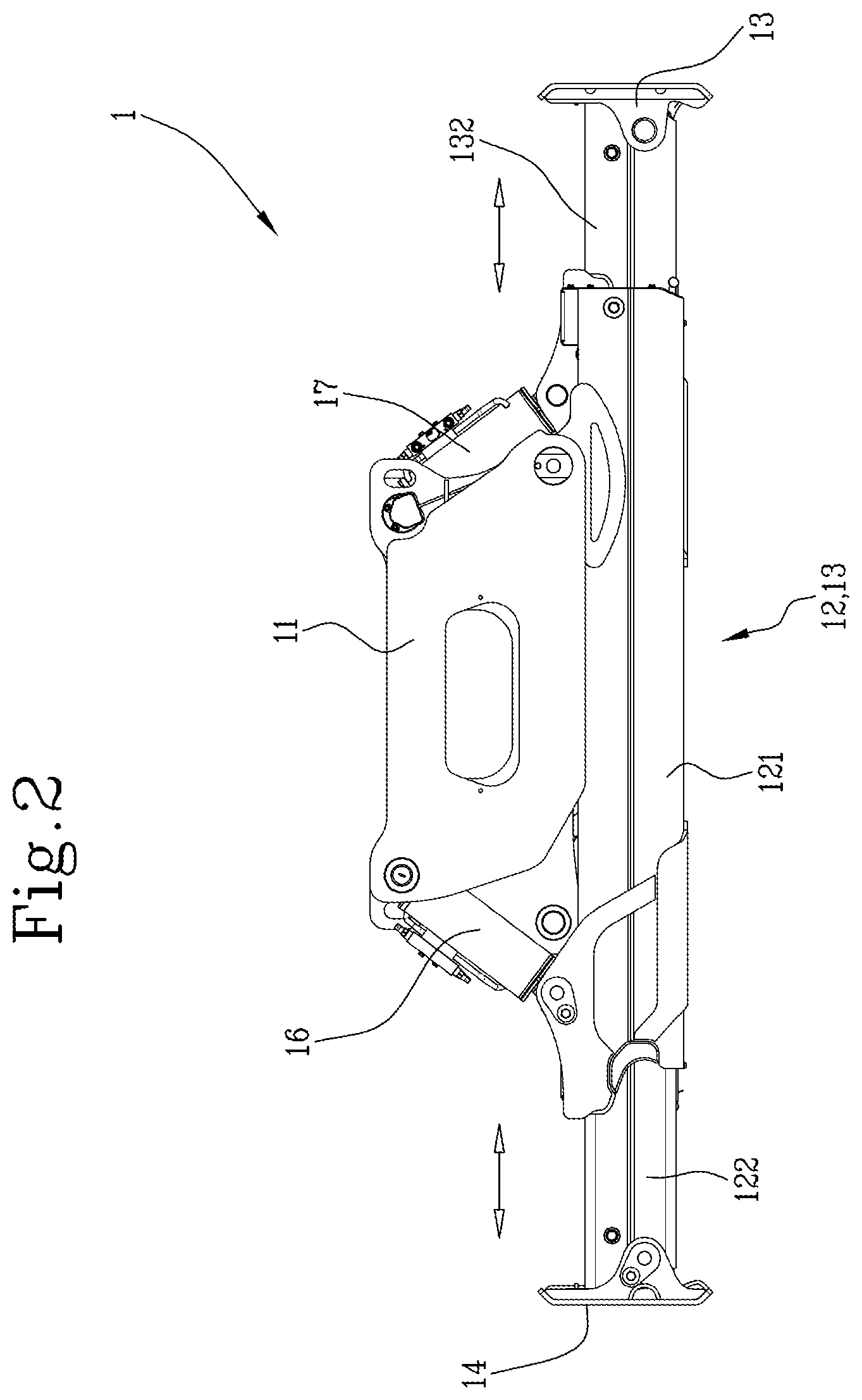
[0011] FIGS. 2 and 3 are front views of the stabilisers according to the invention in two different operating positions; and
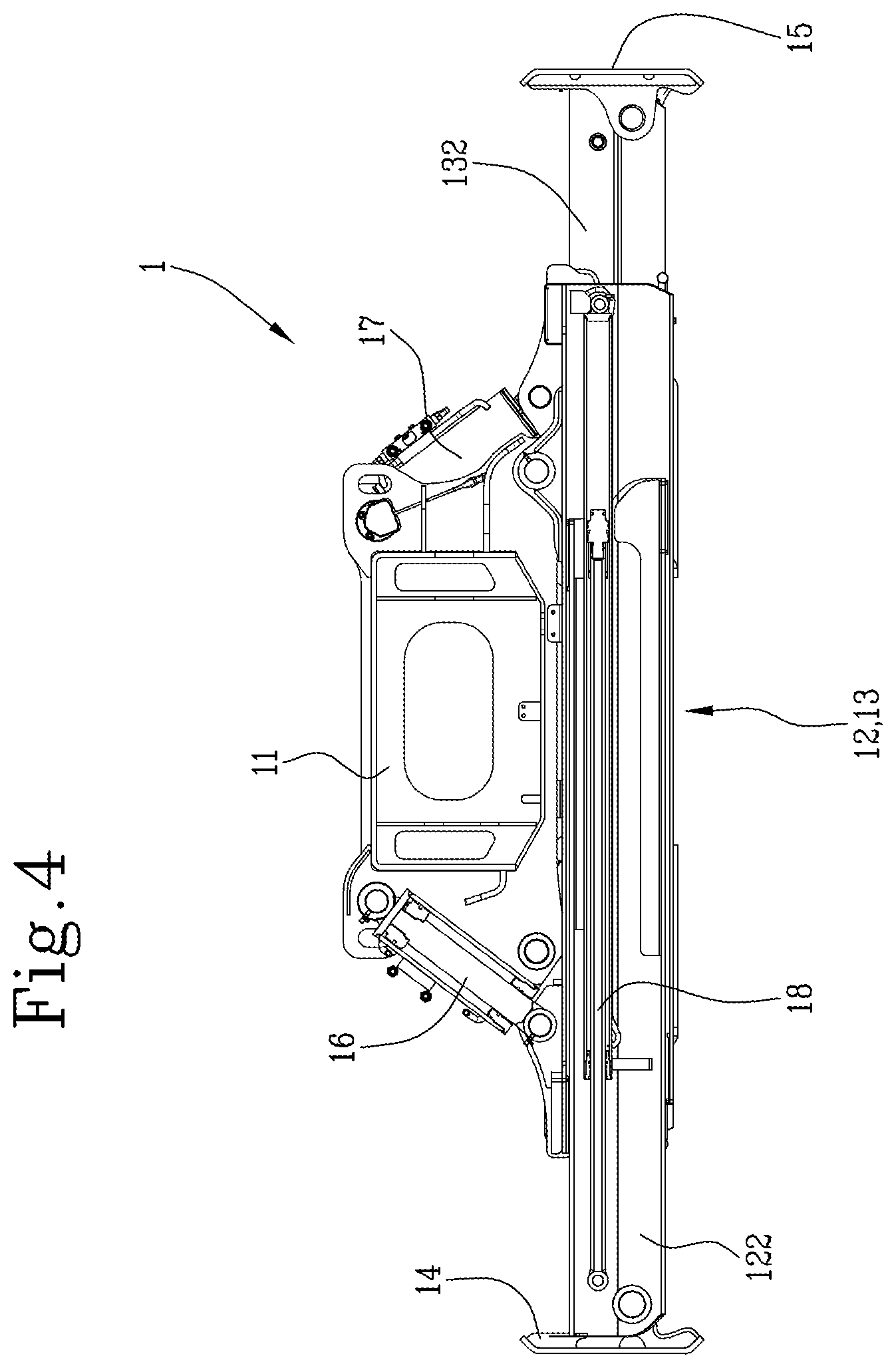
[0012] FIG. 4 is a front cutaway view of the stabilisers of the two previous drawings.
[0013] With reference to the accompanying drawings, the numeral 1 denotes in its entirety electrical stabilisers according to the invention.
[0014] More in detail, the invention has been designed especially but not exclusively for the application to electrical telehandlers 10, that is to say, "full-electric" or hybrid; this does not mean that the proposed stabilisers cannot also be fitted on telehandlers with "classic" drive, that is to say, diesel or in any case an internal combustion engine.
[0015] Moreover, the telehandler 10 on which the invention is intended to be installed may be both fixed and rotary and, in the second case, it is equipped with a rotary tower 100.
[0016] The telehandler 10 includes a carriage 2 movable on four drive wheels 3 and a lifting arm 4, hinged to the carriage 2 or to the tower 100, which can be lifted and extended telescopically using suitable hydraulic actuators, in particular hydraulic cylinders.
[0017] Moreover, at its distal end, the arm 4 is provided with a coupling device 40 which allows the apparatus to be hooked up and replaced, which can in turn be equipped with a hydraulic actuator.
[0018] The hydraulic actuators present in the telehandler 10 are controlled by a hydraulic distributor, mounted on board the vehicle, which is actuated by a hydraulic pump.
[0019] Moreover, the telehandler 10 may be equipped with a cab 5 or be without a cab and therefore only be controlled by a remote control system.
[0020] In both cases, a control unit controls both the operation of the electric motor (or motors) and that of the hydraulic distributor, on the basis of the commands actuated by the operator.
[0021] The stabilisers 1 are mounted in pairs at the opposite longitudinal ends of the carriage 2, that is to say, at the front and at the rear (see FIG. 1).
[0022] More in detail, each pair of stabilisers 1 according to the invention includes a supporting frame 11 directly fixed or welded to the carriage 2 and two telescopic arms 12, 13 fixed to said frame 11, each of which includes a first hollow segment 121, 131 directly connected to the frame 11 and a second hollow segment 122, 132 inserted in a slidable fashion in the first segment, to define a pull-out element, equipped with a foot 14, 15 or support base at the distal end.
[0023] It should be noted that the invention is not limited to the use of a single pull-out element for the arm, as several pull-out elements can be used.
[0024] In the example illustrated, the stabilisers 1 are of the scissor or "X" type, and therefore have the arms 12, 13 which cross each other; in this case, their descent and opening movements to lift the carriage 2 from the ground, in such a way that the wheels 3 are spaced from the ground, for the purposes of stabilising, as well as the return and closing movements, for picking up the stabilisers 1 in the configuration of minimum dimensions, can also be as in traditional scissor-like stabilisers.
[0025] The first segments 121, 131 of the arms 12, 13 are rotationally connected to the frame 11 and there are two linear rotation actuators 16, 17 which allow the oscillation.
[0026] More in detail, the rotation actuators 16, 17 are hinged at a first end to the frame 11 and at an opposite end to a respective first segment 121, 131.
[0027] The elongation of each arm 12, 13 is obtained by means of a pull-out linear actuator of the electric type 18 (shown only in FIG. 4), positioned inside the arm 12, 13 and having one end fixed to the first segment 121, 131 and one end fixed to the second segment 122, 132.
[0028] Therefore, whilst the rotation actuators 16, 17 can be both of the hydraulic type (therefore hydraulic cylinders) and of the electric type, the draw-out actuators 18 according to the invention are necessarily of the electrical type and are subject to the command of the control unit configured for generating extension signals designed to adjust the draw-out of the stabilising arms 12, 13 (shown by the arrows in FIG. 2).
[0029] If there are several pull-out elements for each arm, they may also be actuated by a plurality of linear electric actuators.
[0030] The use of electric actuators for actuating the wires is particularly suited, even if not necessarily, with the implementation of the invention on an electric telehandler 10, which comprises one or more drive apparatuses connected to the four drive wheels 3, an electric motor connected directly to the drive apparatuses and at least one battery or battery pack designed to power the motor.
[0031] More precisely, a transmission without hydraulic components may be defined between the electric motor and the drive wheels.
[0032] It should be noted that the control unit can include a memory module where a lowering sequence of the stabilisers 1 and a recovery sequence of the stabilisers is recorded and a control module of the stabilisers configured to control the hydraulic distributor and the electric draw-out actuators so to automatically perform said sequences.
[0033] More specifically, the control module is designed to produce rotation signals of the arms directed to the distributor for actuating the rotation actuators 16, 17 (see FIG. 3) or extension signals for actuating the sliding actuators 18; if the rotation actuators are of the electric type, they would receive the electrical rotation signals of the arms directly from the control module.
* * * * *
D00000
D00001
D00002
D00003
D00004
XML
uspto.report is an independent third-party trademark research tool that is not affiliated, endorsed, or sponsored by the United States Patent and Trademark Office (USPTO) or any other governmental organization. The information provided by uspto.report is based on publicly available data at the time of writing and is intended for informational purposes only.
While we strive to provide accurate and up-to-date information, we do not guarantee the accuracy, completeness, reliability, or suitability of the information displayed on this site. The use of this site is at your own risk. Any reliance you place on such information is therefore strictly at your own risk.
All official trademark data, including owner information, should be verified by visiting the official USPTO website at www.uspto.gov. This site is not intended to replace professional legal advice and should not be used as a substitute for consulting with a legal professional who is knowledgeable about trademark law.