Ultrasonic Sub-aperture Polishing Of An Optical Element
Sohn; Alexander
U.S. patent application number 16/512762 was filed with the patent office on 2021-01-21 for ultrasonic sub-aperture polishing of an optical element. The applicant listed for this patent is Facebook Technologies, LLC. Invention is credited to Alexander Sohn.
| Application Number | 20210016409 16/512762 |
| Document ID | / |
| Family ID | 1000004212544 |
| Filed Date | 2021-01-21 |

| United States Patent Application | 20210016409 |
| Kind Code | A1 |
| Sohn; Alexander | January 21, 2021 |
ULTRASONIC SUB-APERTURE POLISHING OF AN OPTICAL ELEMENT
Abstract
Aspects of an ultrasonic polishing system include an ultrasonic actuator and a polishing arm. The ultrasonic actuator is configured to generate ultrasonic vibrations and the polishing arm is coupled to the ultrasonic actuator. The polishing arm includes a horn and a polishing ball. The horn has a proximal end and a distal end. The proximal end is coupled to receive the ultrasonic vibrations and the horn is configured to propagate the ultrasonic vibrations from the proximal end to a distal end. The polishing ball is attached to the distal end of the horn, where the polishing ball vibrates in response to the ultrasonic vibrations for polishing a surface of an optical element. The polishing ball is configured to provide a polishing area on the surface of the optical element that is smaller than an aperture of the optical element.
| Inventors: | Sohn; Alexander; (Seattle, WA) | ||||||||||
| Applicant: |
|
||||||||||
|---|---|---|---|---|---|---|---|---|---|---|---|
| Family ID: | 1000004212544 | ||||||||||
| Appl. No.: | 16/512762 | ||||||||||
| Filed: | July 16, 2019 |
| Current U.S. Class: | 1/1 |
| Current CPC Class: | B24B 13/01 20130101; B24B 1/04 20130101 |
| International Class: | B24B 13/01 20060101 B24B013/01; B24B 1/04 20060101 B24B001/04 |
Claims
1. An ultrasonic polishing system for polishing an optical element, the system comprising: an ultrasonic actuator configured to generate ultrasonic vibrations; and a polishing arm coupled to the ultrasonic actuator, wherein the polishing arm includes: a horn having a proximal end coupled to receive the ultrasonic vibrations, wherein the horn is configured to propagate the ultrasonic vibrations from the proximal end to a distal end of the horn; and a polishing ball attached to the distal end of the horn, wherein the polishing ball is configured to vibrate in response to the ultrasonic vibrations for polishing a surface of the optical element, and wherein the polishing ball is configured to provide a polishing area on the surface of the optical element that is smaller than an aperture of the optical element.
2. The ultrasonic polishing system of claim 1, wherein the aperture of the optical element is 3 millimeters or smaller.
3. The ultrasonic polishing system of claim 1, wherein the polishing area has a diameter of 10 micrometers or smaller.
4. The ultrasonic polishing system of claim 1, wherein the polishing ball has a spherical shape.
5. The ultrasonic polishing system of claim 1, wherein the polishing ball comprises sapphire.
6. The ultrasonic polishing system of claim 1, wherein the polishing arm has a natural frequency that matches a frequency of the ultrasonic vibrations.
7. The ultrasonic polishing system of claim 1, wherein a frequency of the ultrasonic vibrations is greater than 20 kHz.
8. The ultrasonic polishing system of claim 1, wherein a frequency of the ultrasonic vibrations is between 20 kHz and 40 kHz.
9. The ultrasonic polishing system of claim 1, further comprising: a computer numerical control (CNC) positioner coupled to the polishing arm to vary a position of the polishing ball relative to the surface of the optical element.
10. The ultrasonic polishing system of claim 9, further comprising: a computing device that includes: at least one processor; and at least one memory coupled to the at least one processor, the at least one memory having instructions stored therein, which when executed by the at least one processor, direct the computing device to: generate one or more control signals to direct the CNC positioner to vary the position of the polishing ball relative to the surface of the optical element.
11. The ultrasonic polishing system of claim 10, wherein the instructions to generate the one or more control signals to direct the CNC positioner to vary the position of the polishing ball comprise instructions to direct the polishing ball along a polishing path on the surface of the optical element.
12. The ultrasonic polishing system of claim 11, wherein the instructions to direct the polishing ball along the polishing path comprise instructions to vary at least one of: (a) a load applied to the polishing arm, or (b) a velocity of the polishing ball along the polishing path, to adjust an amount of material removed from the surface of the optical element at one or more positions along the polishing path.
13. The ultrasonic polishing system of claim 11, further comprising: an interferometer disposed to obtain one or more surface measurements of the optical element, wherein the at least one memory further comprises instructions to direct the computing device to generate a surface error map of the optical element based on the surface measurements, and wherein the instructions to vary the load or velocity are responsive to the surface error map.
14. The ultrasonic polishing system of claim 1, wherein the ultrasonic actuator comprises a magnetostrictive actuator and wherein the polishing ball is configured to vibrate along an elliptical stroke path on the surface of the optical element in response to the ultrasonic vibrations generated by the magnetostrictive actuator.
15. The ultrasonic polishing system of claim 1, wherein the ultrasonic actuator comprises a piezoelectric actuator and wherein the polishing ball is configured to vibrate along a linear stroke path on the surface of the optical element in response to the ultrasonic vibrations generated by the piezoelectric actuator.
16. A method of ultrasonic sub-aperture polishing of an optical element, the method comprising: enabling an ultrasonic actuator to generate ultrasonic vibrations; and generating one or more control signals to direct a computer numerical control (CNC) positioner to vary a position of a polishing arm relative to a surface of the optical element, wherein the polishing arm includes: a horn having a proximal end coupled to receive the ultrasonic vibrations generated by the ultrasonic actuator, wherein the horn is configured to propagate the ultrasonic vibrations from the proximal end to a distal end of the horn; and a polishing ball attached to the distal end of the horn, wherein the polishing ball is configured to vibrate in response to the ultrasonic vibrations for polishing the surface of the optical element, and wherein the polishing ball is configured to provide a polishing area on the surface of the optical element that is smaller than an aperture of the optical element.
17. The method of claim 16, wherein varying the position of the polishing ball comprises directing the polishing ball along a polishing path on the surface of the optical element, the method further comprising: generating one or more additional control signals to direct the CNC positioner to vary at least one of: (a) a load applied to the polishing arm, or (b) a velocity of the polishing ball along the polishing path, to adjust an amount of material removed from the surface of the optical element at one or more positions along the polishing path.
18. The method of claim 17, further comprising: receiving one or more surface measurements of the optical element; and generating a surface error map of the optical element based on the surface measurements, wherein varying the load or velocity is responsive to the surface error map.
19. An optical element polished by a method comprising: enabling an ultrasonic actuator to generate ultrasonic vibrations; and generating one or more control signals to direct a computer numerical control (CNC) positioner to vary a position of a polishing arm relative to a surface of the optical element, wherein the polishing arm includes: a horn having a proximal end coupled to receive the ultrasonic vibrations generated by the ultrasonic actuator, wherein the horn is configured to propagate the ultrasonic vibrations from the proximal end to a distal end of the horn; and a polishing ball attached to the distal end of the horn, wherein the polishing ball is configured to vibrate in response to the ultrasonic vibrations for polishing the surface of the optical element, and wherein the polishing ball is configured to provide a polishing area on the surface of the optical element that is smaller than an aperture of the optical element.
20. The optical element polishing by the method of claim 19, the method further comprising: receiving one or more surface measurements of the optical element; generating a surface error map of the optical element based on the surface measurements; generating one or more additional control signals in response to the surface error map to direct the CNC positioner to vary at least one of: (a) a load applied to the polishing arm, or (b) a velocity of the polishing ball along a polishing path, to adjust an amount of material removed from the surface of the optical element at one or more positions of the polishing arm along the polishing path.
Description
FIELD OF DISCLOSURE
[0001] Aspects of the present disclosure relate generally to sub-aperture polishing of optical elements, and in particular but not exclusively, relate to ultrasonic sub-aperture polishing of optical elements.
BACKGROUND
[0002] A head mounted display (HMD) is a display device, typically worn on the head of a user. HMDs may be used in a variety of applications, such as gaming, aviation, engineering, medicine, entertainment and so on to provide artificial reality content to a user. Artificial reality is a form of reality that has been adjusted in some manner before presentation to the user, which may include, e.g., virtual reality (VR), augmented reality (AR), mixed reality (MR), hybrid reality, or some combination and/or derivative thereof.
[0003] The accuracy of the various optical elements included in the HMD, such as lenses, polarizers, waveplates, etc. may be dependent on the particular application. For example, some HMDs may incorporate an eye-tracking system that includes an integrated camera to track a user's eye movements. Thus, as the requirements and accuracy for the eye-tracking system increases, the accuracy required in the manufacturing of the various optical elements used by the eye-tracking system also increases.
BRIEF DESCRIPTION OF THE DRAWINGS
[0004] Non-limiting and non-exhaustive aspects of the present disclosure are described with reference to the following figures, wherein like reference numerals refer to like parts throughout the various views unless otherwise specified.
[0005] FIG. 1 illustrates a head mounted display (HMD), in accordance with aspects of the present disclosure.
[0006] FIG. 2 illustrates an example ultrasonic polishing system, in accordance with aspects of the present disclosure.
[0007] FIG. 3 illustrates another example ultrasonic polishing system, in accordance with aspects of the present disclosure.
[0008] FIG. 4 illustrates a polishing path of a polishing ball, in accordance with aspects of the present disclosure.
[0009] FIGS. 5A-5C illustrate various stroke paths, contact areas, and corresponding polishing areas of a polishing ball, in accordance with aspects of the present disclosure.
[0010] FIG. 6 illustrates an example computing device for use with an ultrasonic polishing system, in accordance with aspects of the present disclosure.
[0011] FIG. 7 is a flow chart that illustrates an example process for ultrasonic sub-aperture polishing of an optical element, in accordance with aspects of the present disclosure.
DETAILED DESCRIPTION
[0012] Various aspects and embodiments are disclosed in the following description and related drawings to show specific examples relating to the ultrasonic sub-aperture polishing of an optical element. Alternate aspects and embodiments will be apparent to those skilled in the pertinent art upon reading this disclosure and may be constructed and practiced without departing from the scope or spirit of the disclosure. Additionally, well-known elements will not be described in detail or may be omitted so as to not obscure the relevant details of the aspects and embodiments disclosed herein.
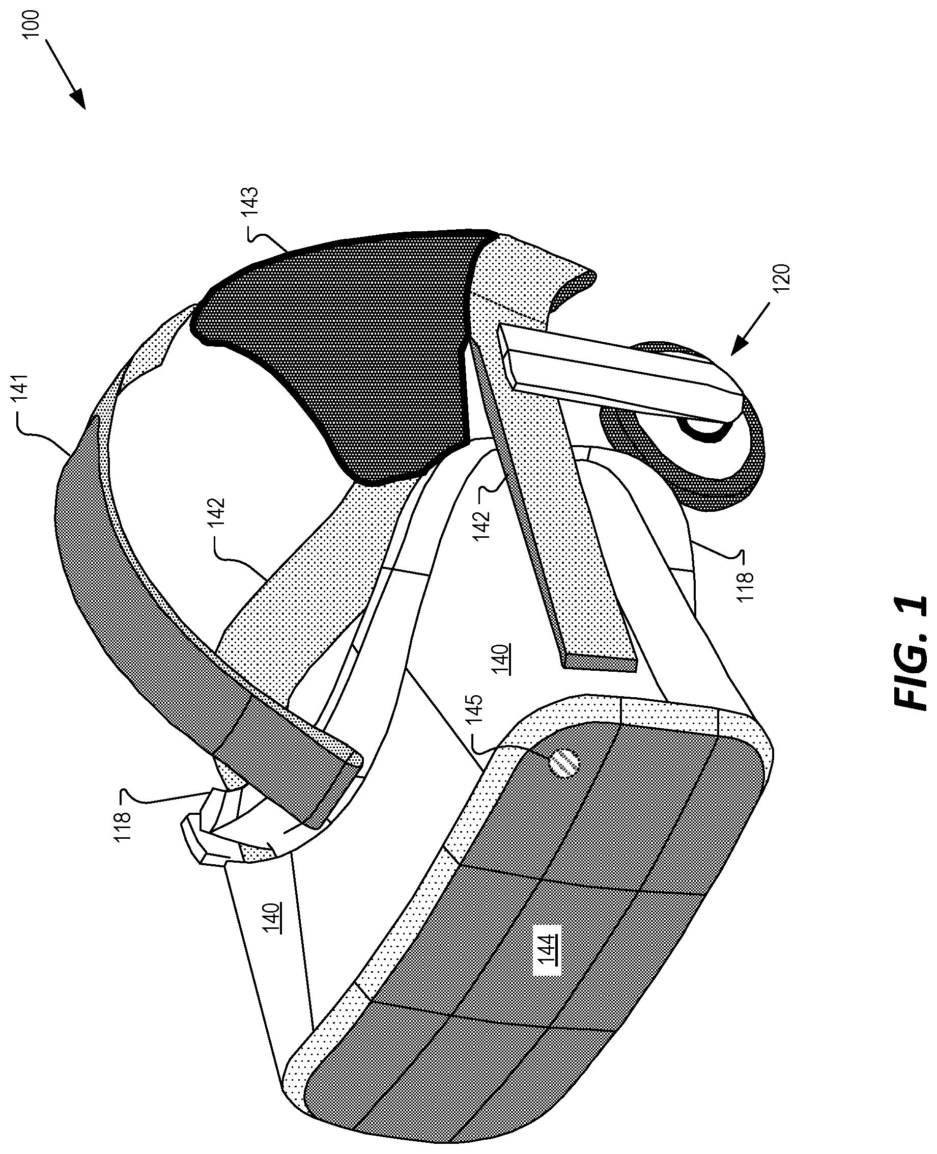
[0013] FIG. 1 illustrates an HMD 100, in accordance with aspects of the present disclosure. The illustrated example of HMD 100 is shown as including a viewing structure 140, a top securing structure 141, a side securing structure 142, a rear securing structure 143, and a front rigid body 144. In some examples, the HMD 100 is configured to be worn on a head of a user of the HMD 100, where the top securing structure 141, side securing structure 142, and/or rear securing structure 143 may include a fabric strap including elastic as well as one or more rigid structures (e.g., plastic) for securing the HMD 100 to the head of the user. HMD 100 may also optionally include one or more earpieces 120 for delivering audio to the ear(s) of the user of the HMD 100.
[0014] The illustrated example of HMD 100 also includes an interface membrane 118 for contacting a face of the user of the HMD 100, where the interface membrane 118 functions to block out at least some ambient light from reaching to the eyes of the user of the HMD 100.
[0015] Example HMD 100 may also include a chassis for supporting hardware of the viewing structure 140 of HMD 100 (chassis and hardware not explicitly illustrated in FIG. 1). The hardware of viewing structure 140 may include any of processing logic, wired and/or wireless data interface for sending and receiving data, graphic processors, and one or more memories for storing data and computer-executable instructions. In one example, viewing structure 140 may be configured to receive wired power and/or may be configured to be powered by one or more batteries. In addition, viewing structure 140 may be configured to receive wired and/or wireless data including video data.
[0016] Viewing structure 140 may include a display system having one or more electronic displays for directing light to the eye(s) of a user of HMD 100. The display system may include one or more of an LCD, an organic light emitting diode (OLED) display, or micro-LED display for emitting light (e.g., content, images, video, etc.) to a user of HMD 100.
[0017] In some examples, a sensor 145 may be included in viewing structure 140. In some aspects, the sensor 145 is a camera for capturing image(s) of an eye of a user of HMD 100 for eye-tracking operations. In other aspects, the sensor 145 is a Simultaneous Localization and Mapping (SLAM) sensor, such as an optical sensor, rangefinder, LiDAR sensor, sonar sensor, etc., for mapping the user and/or environment surrounding the HMD 100.
[0018] In some aspects, the sensor 145 may include one or more small-diameter optical elements, such as a lens, a polarizer, a waveguide, reflector, a waveplate, etc. In some aspects, a "small-diameter" optical element refers to an optical element having a diameter (e.g., aperture) that is 3 millimeters or less. As mentioned above, as the requirements and accuracy for the various systems (e.g., eye-tracking system or SLAM system) of an HMD increases, so too does the accuracy required in the manufacturing of the various small-diameter optical elements.
[0019] The manufacture of a conventional optical element typically begins with the generation of the optical element's rough shape by diamond turning, grinding a blank or by forming the optical element in a mold. Subsequently, the optical element or its mold may be polished to its final form to achieve the desired shape and/or surface finish. In one example, polishing may be employed to remove "high spots" on the optical surface. Conventional polishing approaches involve utilizing a rotating pad or spinning wheel that is applied to the optical surface. However, for small-diameter optical elements (e.g., lenses with an aperture less than 3 mm) it is difficult to achieve the desired accuracy using a rotating pad or spinning wheel.
[0020] Accordingly, aspects of the present disclosure are directed to the sub-aperture polishing of optical surfaces, such as the surfaces of molds used to form the various optical elements, and/or the surfaces of the optical elements themselves. In some aspects, a high-frequency (e.g., ultrasonic (>20 kHz)) actuator is utilized for sub-aperture polishing of various optical elements. For example, as will be described below, a high-frequency actuator may be configured to vibrate a polishing arm that includes a polishing ball attached to an end of a horn. The polishing of an optical element, according to aspects described herein, may provide a polishing area that is less than 10 microns in diameter.
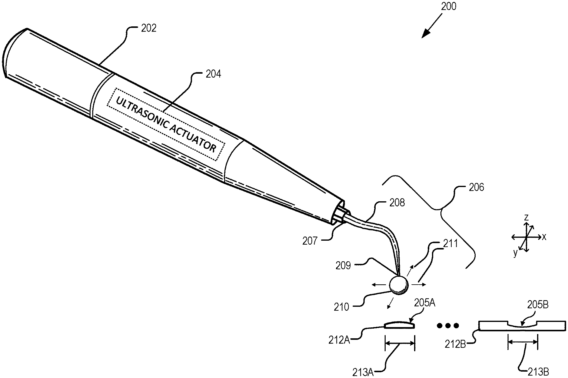
[0021] FIG. 2 illustrates an ultrasonic polishing system, in accordance with aspects of the present disclosure. The illustrated example of ultrasonic polishing system 200 is shown as including a housing 202, an ultrasonic actuator 204, and a polishing arm 206. The example polishing arm 206 is shown as including a horn 208 and a polishing ball 210. FIG. 2 also illustrates optical elements 212A and 212B. As shown in FIG. 2, optical element 212A is illustrated as a lens having an optical surface 205A and an aperture 213A, whereas optical element 212B is illustrated as a mold having a surface 205B and an aperture 213B.
[0022] Ultrasonic actuator 204 is shown as being included in the housing 202 and is configured to generate ultrasonic vibrations. In one example, a frequency of the ultrasonic vibrations is greater than 20 kHz. In another example, the frequency of the ultrasonic vibrations is in the range of 20 kHz to 40 kHz. In some implementations, the ultrasonic actuator 204 includes a magnetostrictive actuator. The magnetostrictive actuator may include a ferromagnetic material that generates the ultrasonic vibrations responsive to a magnetic field applied to the ferromagnetic materials. In another implementation, the ultrasonic actuator 204 includes a piezoelectric actuator. The piezoelectric actuator may include a solid material (e.g., crystal, ceramic, etc.) that generates the ultrasonic vibrations in response to an electrical field applied to the solid material.
[0023] As shown in FIG. 2, the polishing arm is coupled to the housing to receive the ultrasonic vibrations generated by the ultrasonic actuator 204. In particular, a proximal end 207 of the horn 208 is coupled to the ultrasonic actuator 204 to receive the ultrasonic vibrations. In operation, the horn 208 is configured to propagate the ultrasonic vibrations from the proximal end 207 to a distal end 209 of the horn 208. In some examples, horn 208 may be made from a metal, such as a stainless-steel alloy. Furthermore, although FIG. 2 illustrates horn 208 as having a curved shape, in other implementations, horn 208 may have a variety of shapes, such as a straight shape, or a shape with multiple curves.
[0024] Attached to the distal end 209 of the horn 208, is a polishing ball 210. In some examples, polishing ball 210 is attached to the distal end 209 of the horn 208 by way of a glue, epoxy, or other adhesive. In some examples, polishing ball 210 is soldered to the distal end 209. In yet another example, polishing ball 210 may include a threaded cavity for securing it to the distal end 209.
[0025] Polishing ball 210 may be made from a variety of materials such as sapphire, ceramics or polymers. As shown in FIG. 2, the polishing ball 210 may have a spherical shape. In some examples, the polishing ball 210 may have a diameter that is 3 millimeters or smaller. In one embodiment, the polishing ball 210 has a diameter in the range of 0.5 millimeters to 3 millimeters.
[0026] In operation, the polishing ball 210 is configured to vibrate in response to the ultrasonic vibrations. As shown in FIG. 2, the polishing ball 210 is configured to provide lateral vibrations 211 (i.e., along the x-y plane) responsive to the ultrasonic vibrations propagated to the distal end 209 of the horn 208. In some examples, polishing arm 206, including the horn 208 and the polishing ball 210, has a natural frequency that matches the frequency of the ultrasonic vibrations generated by the ultrasonic actuator 204. In some embodiments, a combined mass of the horn 208 and polishing ball 210 is configured to provide a natural frequency of the polishing arm 206 that matches the frequency of the ultrasonic vibrations. In other examples, a frequency of the ultrasonic vibrations generated by the ultrasonic actuator 204 is tuned to match the natural frequency of the polishing arm 206.
[0027] As will be described in more detail below with reference to FIGS. 4 and 5, the polishing ball 210 is configured to provide a polishing area on a surface of an optical element that is smaller than an aperture of the optical element, itself. For example, as mentioned above, optical element 212A is shown in FIG. 2 as a lens having an aperture 213A. Thus, the polishing ball 210 may be applied to the surface 205A to provide a polishing area that is smaller than the aperture 213A. In some examples, the optical element 212A may be glass or polymer. By way of another example, the optical element 212B is shown in FIG. 2 as a mold used for forming various small-diameter optics, such as a lens. The optical element 212B is shown as including an aperture (i.e., diameter) 213B. Thus, the polishing ball 210 may be applied to the surface 205B to provide a polishing area that is smaller than aperture 213B. In some examples, the apertures 213A/213B are 3 millimeters or smaller and the polishing area provided by the polishing ball 210 has a diameter that is 10 micrometers or smaller.
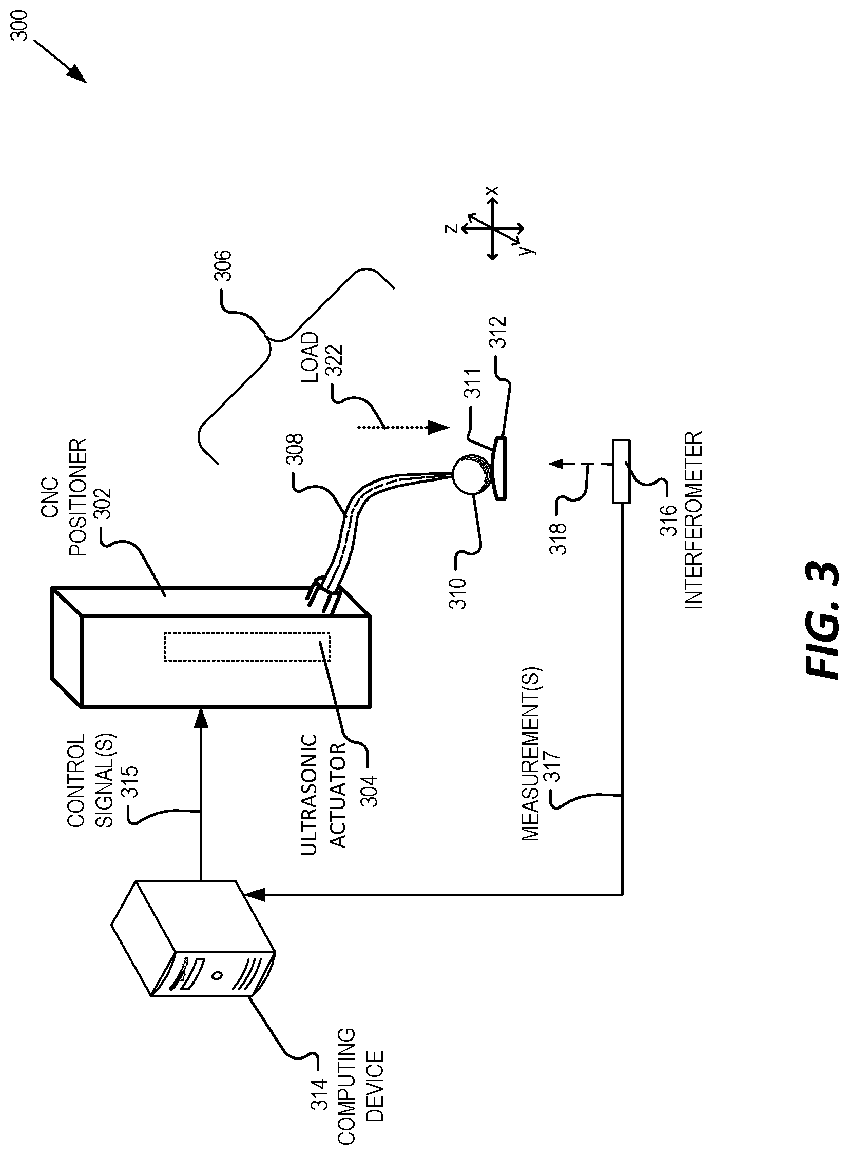
[0028] FIG. 3 illustrates an ultrasonic polishing system 300, in accordance with aspects of the present disclosure. The illustrated example of ultrasonic polishing system 300 is shown as including a computer numerical control (CNC) positioner 302, an ultrasonic actuator 304, a polishing arm 306, a computing device 314, and an interferometer 316. The polishing arm 306 is shown as including a horn 308 and a polishing ball 310. Also shown in FIG. 3 is an optical element 312.
[0029] Ultrasonic actuator 304, polishing arm 306, horn 308, and polishing ball 310 are configured similarly to corresponding components 204, 206, 208, and 210, described above with reference to FIG. 2. As shown in FIG. 3, ultrasonic actuator 304 and polishing arm 306 may be attached to, or incorporated into, a CNC positioner 302 to vary a position of the polishing ball 310 relative to a surface 311 of the optical element 312.
[0030] In one aspect, CNC positioner 302 is a motorized maneuverable platform that is controlled by one or more control signals 315 generated by a computing device 314. In some examples, CNC positioner 302 is a CNC mill that is configured to move the polishing arm 306 and/or the optical element 312 to various locations and/or depths. In some embodiments, CNC positioner 302 may include one or more direct-drive stepper motors or servo motors in order to provide highly accurate movements of the polishing arm 306, and thus polishing ball 310, along multiple axes (e.g., X, Y, and Z axes).
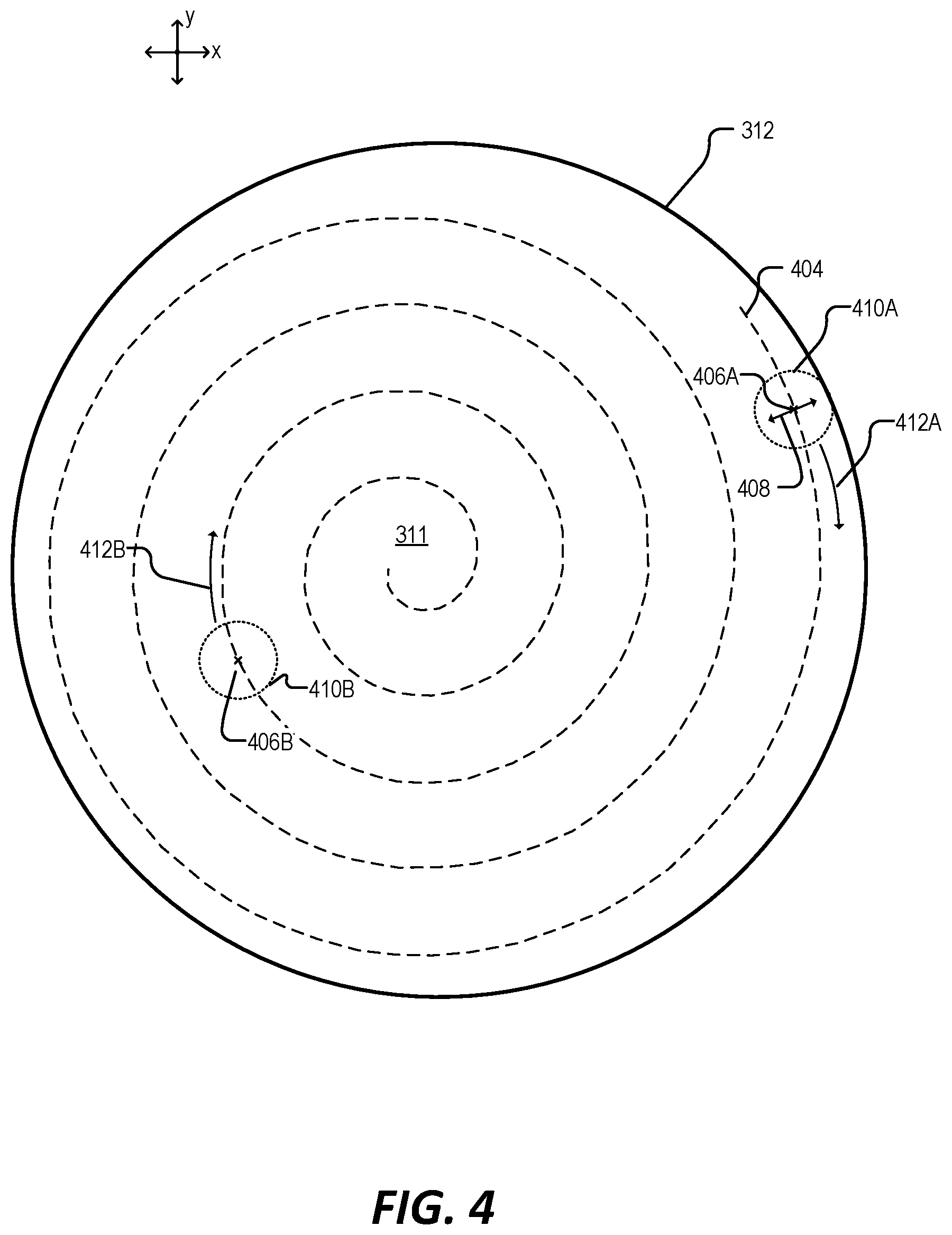
[0031] In some aspects, the computing device 314 is configured to generate the control signals 315 to direct the CNC positioner 302 to vary the position of the polishing ball 310 and/or optical element 312, to direct the polishing ball 310 along a polishing path on the surface 311 of the optical element 312. By way of example, FIG. 4 illustrates a top view of a polishing path 404 of polishing ball 310 along surface 311 of optical element 312, in accordance with aspects of the present disclosure. In some aspects, the CNC positioner 302 is configured to direct the polishing ball 310 along the polishing path 404 to polish the entirety of surface 311 in a contiguous manner Thus, FIG. 4 illustrates the polishing path 404 as having a spiral pattern. However, various other patterns such as raster or quasi-random meander for polishing path 404 may be utilized for polishing the surface 311.
[0032] FIG. 4 illustrates various positions (e.g., position 406A and position 406B) of the polishing ball 310 as the CNC positioner 302 directs the polishing ball 310 along the polishing path 404. As mentioned above, the polishing ball 310 may laterally vibrate in response to the ultrasonic vibrations generated by the ultrasonic actuator. Thus, in operation the polishing ball 310 may vibrate on a stroke path 408 (e.g., due to the lateral vibrations) as the polishing ball is directed along the polishing path 404. When at position 406A, the polishing ball 310 may vibrate along the stroke path 408 to provide a polishing area 410A. As mentioned above, the polishing area 410A may have a diameter that is 10 micrometers or less.
[0033] In some examples, the CNC positioner 302 may be directed, by the computing device 314, to vary one or more parameters as the polishing ball 310 is directed along the polishing path 404 to adjust an amount of material removed from the surface 311 at one or more positions. In one aspect, the CNC positioner 302 may adjust a velocity with which the polishing ball 310 is directed along the polishing path 404. By way of example, the CNC positioner 302 may move the polishing ball 310 at a first velocity 412A as the polishing ball 310 passes through position 406A. However, the velocity may be adjusted to a second velocity 412B as the polishing ball 310 passes through position 406B. In one example, the CNC positioner 302 may decrease the velocity of the polishing ball 310 to increase the amount of time that the polishing ball 310 remains over an area of the surface 311 to increase the amount of material that is removed from the surface 311.
[0034] Returning now to FIG. 3, the CNC positioner 302 may also be configured to vary a load 322 that is applied by the polishing ball 310 to the surface 311. In some aspects, the load 322 is a downward mechanical force applied by the CNC positioner 302 to the polishing arm 306. In some examples, the CNC positioner 302 may adjust the load 322, responsive to control signals 315, to adjust a size of the polishing area (e.g., polishing area 410A and/or 410B of FIG. 4). In one aspect, the CNC positioner 302 may increase the load 322 to increase the size of the polishing area provided by the polishing ball 310. In another aspect, the CNC positioner 302 may increase the load 322 at one or more positions along the polishing path to increase the amount of material removed from the surface 311.
[0035] As discussed above, the computing device 314 is configured to generate the control signals 315 to direct the CNC positioner 302 to vary the position of the polishing ball 310 along a polishing path (e.g., polishing path 404 of FIG. 4). In addition, the computing device 314 may be configured to vary one or more parameters (e.g., velocity and/or load) of the CNC positioner 302 to adjust the amount of material that is removed by the polishing ball 310 at various positions along the polishing path 404. In some examples, the computing device 314 is configured to vary the one or more parameters based on a surface error map of the optical element 312. In one aspect, a surface error map is a representation of the current surface 311 of the optical element 312 and may identify one or more high spots and/or low spots on the surface 311. In another aspect, the surface error map may identify one or more locations on the surface 311 that deviate from a desired shape of the optical element 312.
[0036] Thus, in some examples, the ultrasonic polishing system 300 may include an interferometer 316 that is disposed to obtain one or more surface measurements (i.e., measurements 317) of the optical element 312. In one aspect, interferometer 316 is configured to measure small displacements, refractive index changes, and/or surface irregularities of the optical element 312. By way of example, interferometer 316 may generate a single source of light 318 at various locations of the optical element 312. The single source of light 318 may be split into two beams that travel in different optical paths, which are then combined to produce interference. The interference may then be analyzed to generate the measurements 317. In response to receiving the measurements 317, the computing device 314 may generate a surface error map, which it then uses to generate the removal map. In some aspects, the one or more control signals 315 are generated by the computing device 314 based on the removal map.
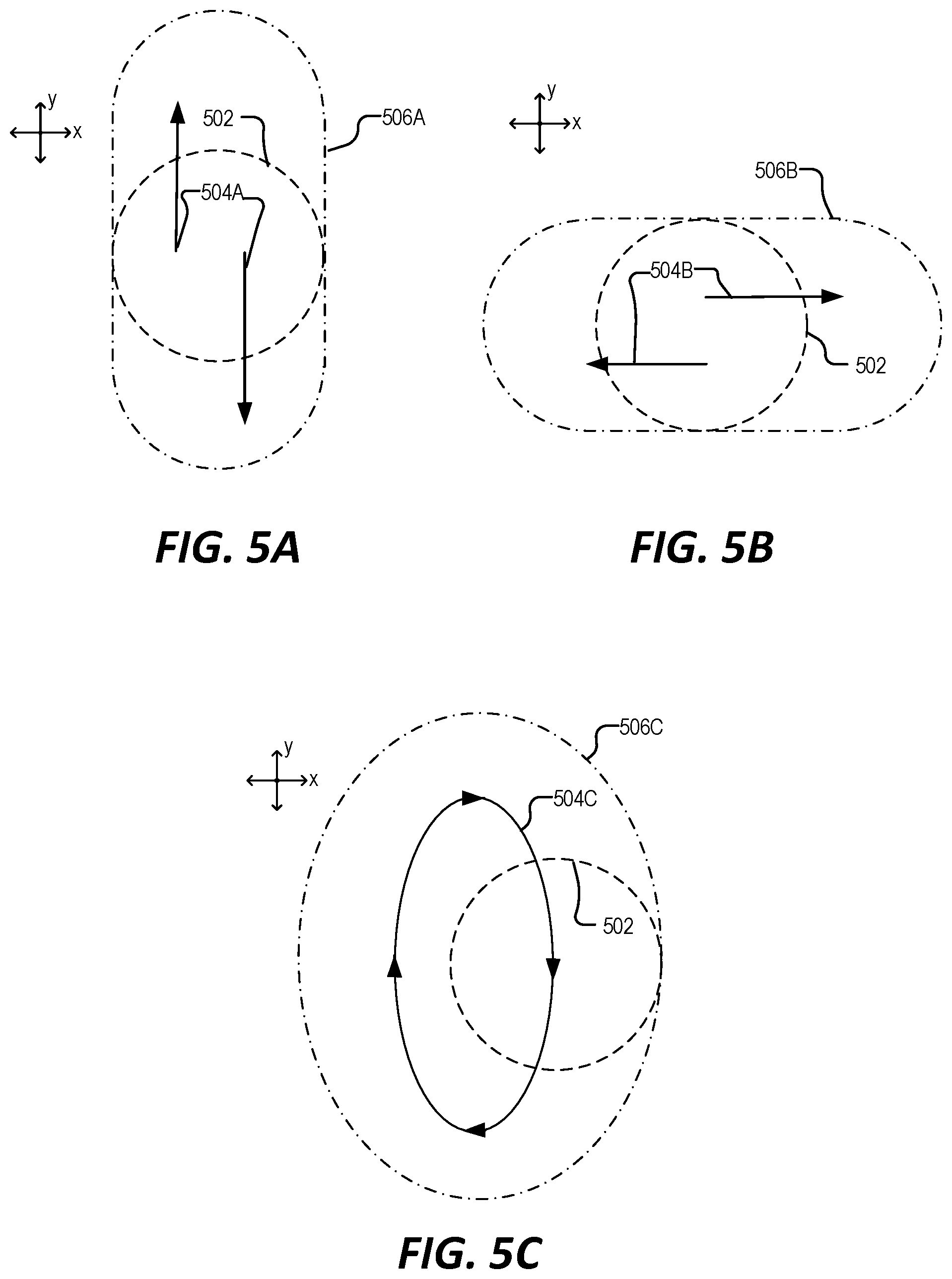
[0037] As mentioned above, as the polishing ball (e.g., polishing ball 310 of FIG. 3) is directed along a polishing path the polishing ball may also follow a stroke path (e.g., due to the lateral vibrations). Thus, FIGS. 5A-5C illustrate various stroke paths (e.g., stroke paths 504A, 504B, and 504C), contact areas (e.g., contact area 502), and corresponding polishing areas (e.g., polishing areas 506A, 506B, and 506C) of a polishing ball, in accordance with aspects of the present disclosure.
[0038] FIG. 5A illustrates an example contact area 502. In some aspects, the contact area 502 represents the area of contact between the polishing ball and the surface of the optical element. The size of the contact area 502 may be dependent on a variety of factors, such as the load applied to the polishing ball, the diameter of the polishing ball, and the material properties of the polishing ball and/or of the optical element, itself. In operation, the polishing ball may vibrate in response to the ultrasonic vibrations to provide a stroke path 504A which results in an effective polishing area 506A. The polishing area 506A may have a diameter that is less than 10 micrometers.
[0039] As shown in FIG. 5A, the stroke path 504A is a linear stroke path that provides movement of the polishing ball along the Y-axis in response to the ultrasonic vibrations. In one example, a linear stroke path is provided in response to ultrasonic vibrations generated by a piezoelectric actuator that may be included in the ultrasonic actuator (e.g., ultrasonic actuator 304 of FIG. 3).
[0040] FIG. 5B illustrates a stroke path 504B that is another linear stroke path, but one that provides movement of the polishing ball along the X-axis. As shown, movement of the polishing ball along the stroke path 504B provides an effective polishing area 506B. Similar to the stroke path 504A, discussed above, the stroke path 504B of FIG. 5B may be generated in response to ultrasonic vibrations generated by a piezoelectric actuator.
[0041] FIG. 5C illustrates an example elliptical stroke path 504C. As shown in FIG. 5C, the elliptical stroke path 504C provides for elliptical movement of the polishing ball on the X-Y plane to provide an effective polishing area 506C. In one example, the elliptical stroke path 504C is provided in response to ultrasonic vibrations generated by a magnetostrictive actuator that may be included in the ultrasonic actuator (e.g., ultrasonic actuator 304 of FIG. 3).
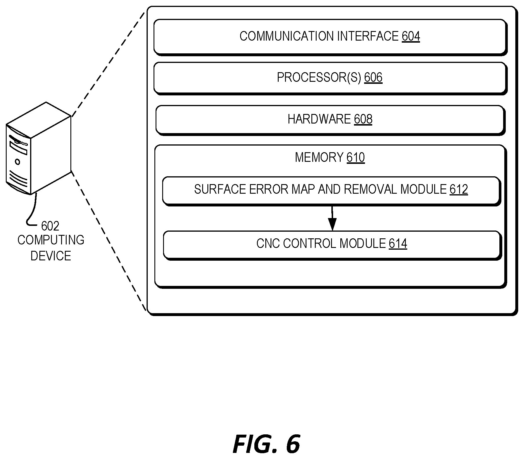
[0042] FIG. 6 illustrates an example computing device 602 for use with an ultrasonic polishing system, in accordance with aspects of the present disclosure. The illustrated example of computing device 602 is shown as including a communication interface 604, one or more processors 606, hardware 608, and a memory 610. Computing device 602 is one possible implementation of computing device 314 of FIG. 3.
[0043] The communication interface 604 may include wireless and/or wired communication components that enable the computing device 602 to transmit data to and receive data from other devices, such as the CNC positioner 302 of FIG. 3. The hardware 608 may include additional hardware interface, data communication, or data storage hardware. For example, the hardware interfaces may include a data output device (e.g., electronic display, audio speakers), and one or more data input devices.
[0044] The memory 610 may be implemented using computer-readable media, such as computer storage media. In some aspects, computer-readable media may include volatile and/or non-volatile, removable and/or non-removable media implemented in any method or technology for storage of information such as computer-readable instructions, data structures, program modules, or other data. Computer-readable media includes, but is not limited to, RAM, ROM, EEPROM, flash memory or other memory technology, CD-ROM, digital versatile disks (DVD), high-definition multimedia/data storage disks, or other optical storage, magnetic cassettes, magnetic tape, magnetic disk storage or other magnetic storage devices, or any other non-transmission medium that can be used to store information for access by a computing device.
[0045] The processors 606 and the memory 610 of the computing device 602 may implement a surface error map and removal module 612 and a CNC control module 614. The surface error map and removal module 612 and the CNC control module 614 may include routines, program instructions, objects, and/or data structures that perform particular tasks or implement particular abstract data types. The memory 610 may also include a data store (not shown) that is used by the surface error map and removal module 612 and/or CNC control module 614.
[0046] The surface error map and removal module 612 may be configured to generate a surface error map and a removal map of the optical element (e.g., optical element 312 of FIG. 3). In one example, the surface error map and removal module 612 may generate the surface error map in response to one or more measurements obtained from an interferometer (e.g., measurements 317 generated by interferometer 316 of FIG. 3). In other examples, the surface error map and removal module 612 may generate the surface error map based on one or more other optical metrology techniques, such as direct surface profiling (e.g., by way of a profilometer).
[0047] The CNC control module 614 is configured to generate one or more control signals (e.g., control signals 315 of FIG. 3) to direct a CNC positioner (e.g., CNC positioner 302 of FIG. 3) to vary a position of a polishing arm (e.g., polishing arm 306) relative to a surface of an optical element (e.g., surface 311 of optical element 312). In some examples, the CNC control module 614 is configured to generate the control signals based on the removal map generated by the surface error map and removal module 612. For example, the removal map may identify one or more areas on the surface 311 of the optical element 312 that are high areas, or areas at which additional material needs to be removed. Thus, the CNC control module 614 may generate the control signals to vary the load and/or velocity of the polishing ball as it is directed along the polishing path to increase the amount of material that is removed from the surface of the optical element when the polishing ball is at a position corresponding to the identified high areas of the optical element.
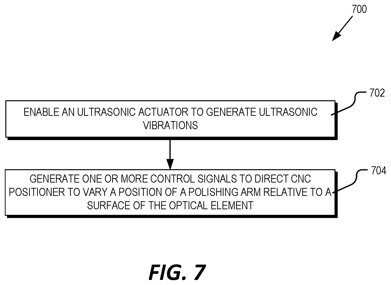
[0048] FIG. 7 is a flow chart that illustrates an example process 700 for ultrasonic sub-aperture polishing of an optical element, in accordance with aspects of the present disclosure. Process 700 is one example process that may be performed by computing device 314 of FIG. 3 and/or computing device 602 of FIG. 6.
[0049] In a process block 702, the ultrasonic actuator (e.g., ultrasonic actuator 304) is enabled to generate ultrasonic vibrations. In one aspect, the CNC control module 614 may enable the ultrasonic actuator by generating one or more control signals 315 via communication interface 604. Next, in a process block 704, the CNC control module 614 generates one or more of the control signals (e.g., control signals 315) to vary a position of the polishing arm (e.g., polishing arm 306 of FIG. 3) to vary a position of the polishing arm relative to a surface of the optical element.
[0050] As mentioned above, in some example, the CNC control module 614 may generate the control signals to vary a parameter, such as load and/or velocity of the polishing arm based on a surface error map of the optical element. Thus, process 700 may further include the surface error map and removal module 612 receiving one or more surface measurements (e.g., measurements 317 of FIG. 3) and generating the surface error map of the optical element based on the surface measurements. The CNC control module 614 may then generate one or more additional control signals to vary the load and/or velocity at various positions of the polishing ball along the optical path to adjust and amount of material that is removed from the surface of the optical element.
[0051] Embodiments of the invention may include or be implemented in conjunction with the manufacture of an artificial reality system. Artificial reality is a form of reality that has been adjusted in some manner before presentation to a user, which may include, e.g., a virtual reality (VR), an augmented reality (AR), a mixed reality (MR), a hybrid reality, or some combination and/or derivatives thereof. Artificial reality content may include completely generated content or generated content combined with captured (e.g., real-world) content. The artificial reality content may include video, audio, haptic feedback, or some combination thereof, and any of which may be presented in a single channel or in multiple channels (such as stereo video that produces a three-dimensional effect to the viewer). Additionally, in some embodiments, artificial reality may also be associated with applications, products, accessories, services, or some combination thereof, that are used to, e.g., create content in an artificial reality and/or are otherwise used in (e.g., perform activities in) an artificial reality. The artificial reality system that provides the artificial reality content may be implemented on various platforms, including a head-mounted display (HMD) connected to a host computer system, a standalone HMD, a mobile device or computing system, or any other hardware platform capable of providing artificial reality content to one or more viewers.
[0052] The above description of illustrated embodiments of the invention, including what is described in the Abstract, is not intended to be exhaustive or to limit the invention to the precise forms disclosed. While specific embodiments of, and examples for, the invention are described herein for illustrative purposes, various modifications are possible within the scope of the invention, as those skilled in the relevant art will recognize.
[0053] These modifications can be made to the invention in light of the above detailed description. The terms used in the following claims should not be construed to limit the invention to the specific embodiments disclosed in the specification. Rather, the scope of the invention is to be determined entirely by the following claims, which are to be construed in accordance with established doctrines of claim interpretation.
* * * * *
D00000
D00001
D00002
D00003
D00004
D00005
D00006
D00007
XML
uspto.report is an independent third-party trademark research tool that is not affiliated, endorsed, or sponsored by the United States Patent and Trademark Office (USPTO) or any other governmental organization. The information provided by uspto.report is based on publicly available data at the time of writing and is intended for informational purposes only.
While we strive to provide accurate and up-to-date information, we do not guarantee the accuracy, completeness, reliability, or suitability of the information displayed on this site. The use of this site is at your own risk. Any reliance you place on such information is therefore strictly at your own risk.
All official trademark data, including owner information, should be verified by visiting the official USPTO website at www.uspto.gov. This site is not intended to replace professional legal advice and should not be used as a substitute for consulting with a legal professional who is knowledgeable about trademark law.