Vessel Sealing Instrument
Roy; Jeffrey M. ; et al.
U.S. patent application number 17/060421 was filed with the patent office on 2021-01-21 for vessel sealing instrument. The applicant listed for this patent is Covidien LP. Invention is credited to Ryan C. Artale, David Galbraith, Roy Goodwin, Mark J. Huseman, Jeffrey M. Roy.
| Application Number | 20210015543 17/060421 |
| Document ID | / |
| Family ID | 1000005121217 |
| Filed Date | 2021-01-21 |


| United States Patent Application | 20210015543 |
| Kind Code | A1 |
| Roy; Jeffrey M. ; et al. | January 21, 2021 |
VESSEL SEALING INSTRUMENT
Abstract
A bipolar electrosurgical instrument is provided. The bipolar electrosurgical instrument includes first and second shafts each having a jaw member extending from a distal end thereof and a handle disposed at a proximal end thereof for effecting movement of the jaw members relative to one another. A first conductive lead is adapted to connect to a first electrical potential and a second conductive lead is adapted to connect to a second electrical potential. One of the first and second conductive leads extends through the pivot to connect to a respective jaw member.
| Inventors: | Roy; Jeffrey M.; (Boulder, CO) ; Huseman; Mark J.; (Broomfield, CO) ; Artale; Ryan C.; (Crested Butte, CO) ; Goodwin; Roy; (Oroville, CA) ; Galbraith; David; (Oroville, CA) | ||||||||||
| Applicant: |
|
||||||||||
|---|---|---|---|---|---|---|---|---|---|---|---|
| Family ID: | 1000005121217 | ||||||||||
| Appl. No.: | 17/060421 | ||||||||||
| Filed: | October 1, 2020 |
Related U.S. Patent Documents
| Application Number | Filing Date | Patent Number | ||
|---|---|---|---|---|
| 15970673 | May 3, 2018 | 10806505 | ||
| 17060421 | ||||
| 14636276 | Mar 3, 2015 | 9974600 | ||
| 15970673 | ||||
| 12895020 | Sep 30, 2010 | 9005200 | ||
| 14636276 | ||||
| Current U.S. Class: | 1/1 |
| Current CPC Class: | A61B 2018/1455 20130101; A61B 2018/0063 20130101; A61B 18/1445 20130101; Y10T 29/49174 20150115; A61B 18/1442 20130101 |
| International Class: | A61B 18/14 20060101 A61B018/14 |
Claims
1-20. (canceled)
21. An electrosurgical instrument, comprising: a first jaw member disposed at a distal end of a first shaft and a second jaw member disposed at a distal end of a second shaft, the second jaw member having a raceway configured to route a conductive lead to one of the first or second jaw members; a pivot disposed on one of the first or second jaw members distal to the raceway, the jaw members movable about the pivot relative to one another; and a longitudinal groove extending through the pivot and configured to receive a knife therethrough for cutting tissue disposed between the jaw members.
22. The electrosurgical instrument according to claim 21, wherein the second jaw member includes a lead guide slot having a proximal end continuous with the raceway.
23. The electrosurgical instrument according to claim 22, wherein the lead guide slot is disposed distal to the pivot.
24. The electrosurgical instrument according to claim 21, wherein the raceway is configured to maintain the conductive lead in a relatively fixed position during movement of the jaw members.
25. The electrosurgical instrument according to claim 21, further comprising a jaw aperture stop disposed on one of the first or second jaw members and configured to limit movement of the jaw members relative to one another.
26. The electrosurgical instrument according to claim 21, further comprising a pivot plate configured to couple to the pivot to couple the first jaw member to the second jaw member.
27. The electrosurgical instrument according to claim 26, wherein the pivot plate is disposed within a circumferential groove defined in one of the first or second jaw members, the circumferential groove configured to facilitate rotation of the pivot during movement of the jaw members.
28. The electrosurgical instrument according to claim 21, further comprising a proximal shaft connector operably coupled to one of the first or second shafts and configured to connect at least one of the first or second jaw members to a source of electrosurgical energy.
29. The electrosurgical instrument according to claim 21, wherein the pivot is configured to be received within an aperture defined through the second jaw member.
30. An end effector for an electrosurgical instrument, comprising: first and second jaw members movable relative to one another about a pivot between an open position and a closed position; a knife channel defined along a distal portion of at least one of the first or second jaw member; and a lead guide slot disposed on one of the first or second jaw members at an angle relative to a longitudinal axis defined through the pivot and configured to receive a conductive lead.
31. The end effector according to claim 30, wherein the lead guide slot is configured to maintain the conductive lead in a relatively fixed position during movement of the first and second jaw members.
32. The end effector according to claim 30, wherein one of the first or second jaw members has a raceway disposed proximal to the pivot.
33. The end effector according to claim 32, wherein the conductive lead is routed through the raceway and the lead guide slot to connect to one of the first or second jaw members.
34. The end effector according to claim 30, wherein the lead guide slot extends between the pivot and the knife channel.
35. The end effector according to claim 30, wherein one of the first or second jaw members has a longitudinal groove disposed in alignment with the knife channel.
36. An end effector for an electrosurgical instrument, comprising: first and second jaw members movable relative to one another about a pivot between an open position and a closed position; a knife channel defined along a distal portion of at least one of the first or second jaw members, the knife channel configured to receive a knife therethrough; and a longitudinal groove extending through the pivot and configured to receive the knife therethrough.
37. The end effector according to claim 36, wherein one of the first or second jaw members has a lead guide slot configured to receive a conductive lead.
38. The end effector according to claim 36, wherein the longitudinal groove is disposed in alignment with the knife channel and configured to align the knife with the knife channel.
39. The end effector according to claim 36, wherein one of the first or second jaw members has a raceway disposed proximal to the pivot and configured to route a conductive lead to one of the first or second jaw members.
40. The end effector according to claim 36, further comprising a jaw aperture stop disposed on one of the first or second jaw members and configured to limit movement of the first and second jaw members relative to one another.
Description
CROSS-REFERENCE TO RELATED APPLICATIONS
[0001] This application is a continuation of U.S. patent application Ser. No. 15/970,673, filed on May 3, 2018, which is a continuation of U.S. patent application Ser. No. 14/636,276, filed on Mar. 3, 2015, now U.S. Pat. No. 9,974,600, which is a continuation of U.S. patent application Ser. No. 12/895,020 filed on Sep. 30, 2010, now U.S. Pat. No. 9,005,200.
INTRODUCTION
[0002] The present disclosure relates to forceps used for open surgical procedures. More particularly, the present disclosure relates to a forceps which applies a combination of mechanical clamping pressure and electrosurgical current to seal tissue.
BACKGROUND
[0003] Electrosurgical forceps, e.g., commonly used in open surgical procedures, are configured to grasp, dissect and/or clamp tissue. Electrosurgical forceps is a simple plier-like tool which utilizes both mechanical clamping action and electrical energy to respectively constrict vessels and effect hemostasis by heating the tissue and blood vessels to coagulate, cauterize and/or seal tissue. Electrosurgical forceps may be configured for monopolar or bipolar use. For the purposes herein, the present disclosure is directed to electrosurgical forceps that are configured for bipolar use.
[0004] Bipolar electrosurgical forceps (forceps) utilize two generally opposing electrodes that are disposed on the inner opposing surfaces of jaw members associated with the end effector of the forceps and that are both electrically coupled to an electrosurgical generator. Each electrode is charged to a different electric potential and includes a respective seal plate; the seal plates are isolated from each other. Design of the isolated seal plates requires separate and unique wires to enable RF energy for vessel sealing (opposite poles for alternating current). Typically, because of the limited space of the forceps, one of the wires is routed directly to one of the seal plates and the other wire is routed indirectly around, i.e., "looped," about a pivot member that pivotably couples a pair of shafts associated with the forceps. Looping one of the wires around the pivot member may result in the "looped" wire being exposed to the surgical environment when the jaw members are moved, e.g., from an open to clamped position. As can be appreciated, exposing the wire to the surgical environment may result in damage to the wire, which, in turn, may decrease the operative life of the forceps. Moreover, "looping" the wire around the pivot member may increase manufacture costs, i.e., more wire is needed to loop around the pivot member, and may increase manufacture time of the forceps, i.e., more time is needed to loop the wire around the pivot member.
SUMMARY
[0005] The present disclosure provides a bipolar electrosurgical instrument for use in open surgery. The bipolar electrosurgical instrument includes first and second shafts each having a jaw member extending from a distal end thereof. A handle is disposed at proximal ends of the shafts for effecting movement of the jaw members relative to one another about an integrally formed bifurcated pivot member that is supported on one of the jaw members. The jaw members are movable relative to one another about the pivot member from a first position wherein the jaw members are disposed in spaced relation relative to one another to a second position wherein the jaw members cooperate to grasp tissue therebetween. A proximal shaft connector operably couples to one of the first and second shafts and is configured to connect the bipolar electrosurgical instrument to a source of electrosurgical energy providing first and second electrical potentials. A first conductive lead is adapted to connect to the first electrical potential and a second conductive lead is adapted to connect to the second electrical potential. One of the first and second conductive leads extends through the pivot to connect to a respective jaw member.
[0006] The present disclosure provides a bipolar electrosurgical instrument for use in open surgery. The bipolar electrosurgical instrument includes first and second shafts each having a jaw member extending from a distal end thereof. A handle is disposed at proximal ends of the shafts for effecting movement of the jaw members relative to one another about a pivot member from a first position wherein the jaw members are disposed in spaced relation relative to one another to a second position wherein the jaw members cooperate to grasp tissue therebetween. A first conductive lead is adapted to connect to a first electrical potential and a second conductive lead is adapted to connect to a second electrical potential. One of the first and second conductive leads extends through the pivot to connect to a respective jaw member.
[0007] The present disclosure also provides a method for routing electrical leads through a bipolar electrosurgical instrument. The method includes forming first and second shafts with respective handles at proximal ends thereof and an end effector having two pivotably coupled jaw members at distal ends thereof. One of the jaw members includes a pivot member integrally formed thereon. The pivot member is configured to receive one of a first conductive lead and a second conductive lead therethrough. A step of the method includes coupling the first and second leads to one of the first and second shafts and routing each of the first and second conductive leads therethrough. One of the first and second conductive leads is coupled directly to one of the jaw members and one of the first and second conductive leads is routed through the pivot member and to the other jaw member.
BRIEF DESCRIPTION OF THE DRAWING
[0008] Various embodiments of the present disclosure are described hereinbelow with references to the drawings, wherein:
[0009] FIG. 1 is a side, perspective view of an open forceps according to an embodiment of the present disclosure;
[0010] FIG. 2 is a enlarged view of the indicated area of detail in FIG. 1 showing an end effector assembly of the open forceps depicted in FIG. 1;
[0011] FIG. 3 is an internal, side view of a jaw member associated with the end effector assembly depicted in FIG. 2 showing the inner-working components thereof;
[0012] FIG. 4 is a enlarged view of the indicated area of detail in FIG. 3 showing a pivot member associated with the open forceps depicted in FIG. 1;
[0013] FIG. 5 is a side view of the jaw members with one of the jaw members shown in phantom illustrating a wire routed through the pivot member of FIG. 4; and
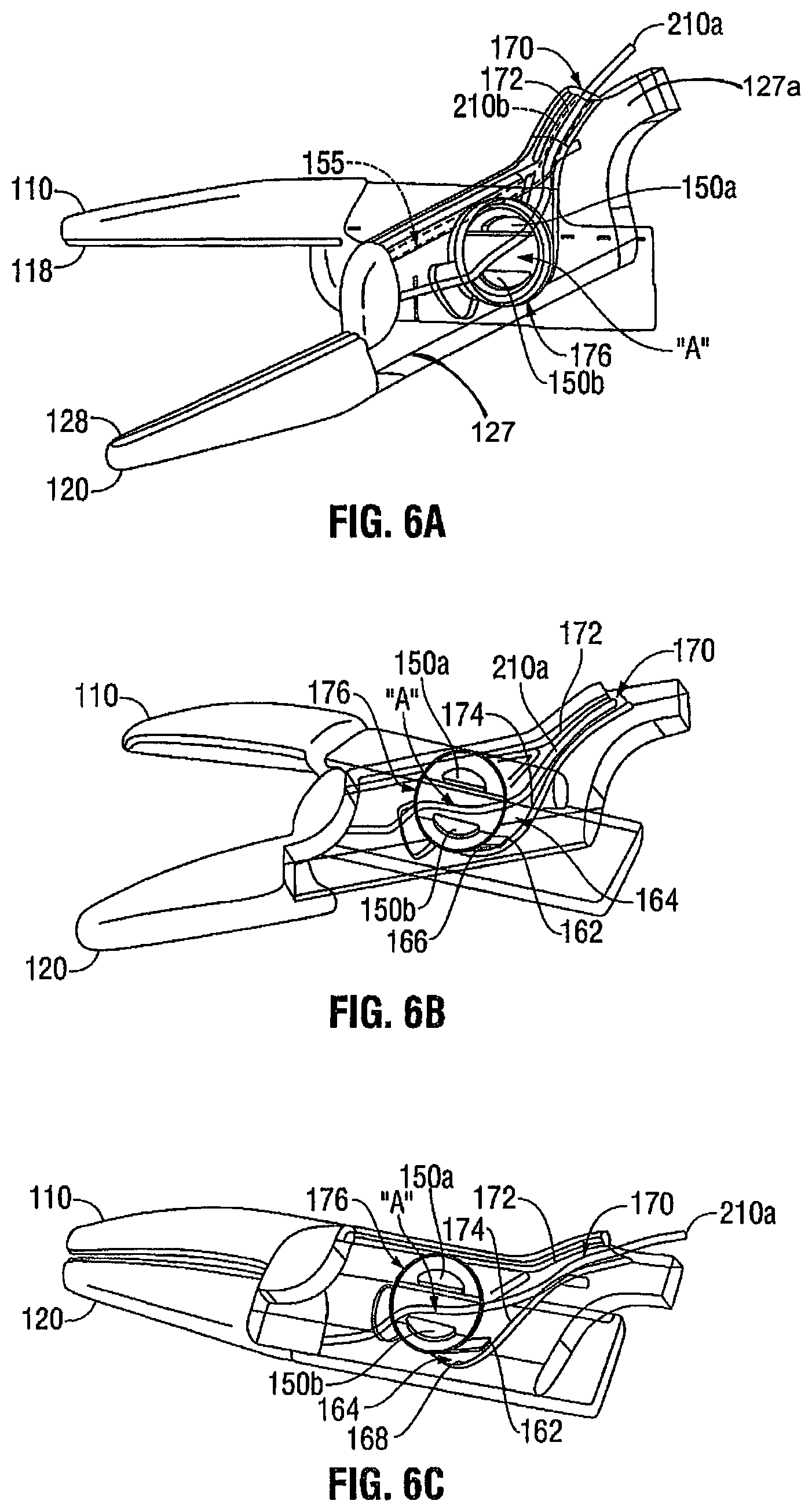
[0014] FIGS. 6A-6C are perspective views illustrating the jaw members in various positions.
DETAILED DESCRIPTION
[0015] Detailed embodiments of the present disclosure are disclosed herein; however, the disclosed embodiments are merely examples of the disclosure, which may be embodied in various forms. Therefore, specific structural and functional details disclosed herein are not to be interpreted as limiting, but merely as a basis for the claims and as a representative basis for teaching one skilled in the art to variously employ the present disclosure in virtually any appropriately detailed structure.
[0016] Referring now to FIGS. 1-6C, and initially with reference to FIG. 1, a forceps 10 for use with open surgical procedures is illustrated. Forceps 10 includes elongated shaft portions 12a and 12b each having a proximal end 16a and 16b, respectively, and a distal end 14a and 14b, respectively. The forceps 10 includes an end effector assembly 100 that attaches to distal ends 14a and 14b of shafts 12a and 12b, respectively. The end effector assembly 100 includes a pair of opposing jaw members 110 and 120 that are pivotably connected about a pivot member 150 (pivot 150).
[0017] In the drawings and in the descriptions which follow, the term "proximal", as is traditional, will refer to the end of the forceps 10 which is closer to the user, while the term "distal" will refer to the end which is further from the user.
[0018] Shaft 12a includes a handle 17a and shaft 12b includes handle 17b. Finger holes 18a and 18b are respectively disposed at the proximal ends 16a and 16b for receiving a finger of the user. As can be appreciated, finger holes 18a and 18b facilitate movement of the shafts 12a and 12b relative to one another which, in turn, pivot the jaw members 110 and 120 from an open position (FIGS. 6A and 6B) wherein the jaw members 110 and 120 are disposed in spaced relation relative to one another to a clamping or closed position (FIGS. 1, 2, 5 and 6C) wherein the jaw members 110 and 120 cooperate to grasp tissue therebetween.
[0019] One of the shafts, e.g., 12b, includes a proximal shaft connector 19 that is designed to connect the forceps 10 to a source of electrosurgical energy such as an electrosurgical generator (not shown). More particularly, proximal shaft connector 19 mechanically cooperates to secure an electrosurgical cable 210 to the forceps 10 such that the user may selectively apply electrosurgical energy as needed. The proximal end of the cable 210 includes a plug (not shown) having a pair of prongs which are configured to electrically and mechanically engage the electrosurgical energy generator. The interior of cable 210 houses a pair of leads 210a and 210b (FIG. 1) which conduct the different electrical potentials from the electrosurgical generator to the jaw members 110 and 120, as explained in greater detail below.
[0020] In certain embodiments, a ratchet (not shown) may be operably coupled to the forceps 10 for selectively locking the jaw members 110 and 120 relative to one another at various positions during pivoting.
[0021] For a more detailed description of the forceps 10 including the ratchet, end effector 100 including jaw members 110 and 120 (and operative components associated therewith), and electrosurgical cable 210 (including line-feed configurations and/or connections), reference is made to commonly owned U.S. Pat. No. 7,329,256 to Johnson et al., filed on Dec. 23, 2005.
[0022] Referring now to FIG. 2, an enlarged view of the end effector 100 is shown. End effector 100 includes opposing jaw members 110 and 120 that are pivotably coupled to each other via the pivot 150 that is integrally formed with one of the jaw members, e.g., jaw member 110. Jaw members 110 and 120 including pivot 150 are configured such that the leads 210a and 210b connect to the respective jaw members 110 and 120 without the need to "loop" one or both of the leads 210a and 210b around the pivot 150 such that exposure of the leads 210a and 210b to the surgical environment is minimized, if not completely eliminated. In the illustrated embodiment, jaw member 110 is supported on shaft 12a at distal end 14a thereof and jaw member 120 is supported on shaft 12b at a distal end 14b thereof (FIG. 1).
[0023] Referring to FIG. 3, jaw member 110 is shown in unassembled and detached from jaw member 120. Jaw member 110 includes a jaw housing 117 having proximal and distal ends 117a and 117b. Distal end 117b is configured to support a seal plate 118 that is isolated from the rest of the jaw housing 117. Proximal end 117a is configured to support the pivot 150. In the illustrated embodiment, the proximal end 117a is elongated with a generally rectangular configuration that may include an arcuate or curved proximal portion (not shown).
[0024] In the embodiment illustrated in the representative figures a generally longitudinal channel 130 of suitable dimensions extends substantially along a length of the proximal end 117a (as best seen in FIG. 3). The channel 130 is configured to receive a cutting element or the like, e.g., a knife blade (not shown). More particularly, the channel 130 is configured such that the cutting element may be translated therethrough for cutting or severing tissue that has been electrosurgically or otherwise treated. The channel 130 is also configured to align the cutting element with a longitudinal knife channel that is operably disposed on one or both of the jaw members 110 and 120. For purposes herein, it may be assumed that the longitudinal knife channel is operably disposed on both the jaw members 110 and 120. The depth of the channel 130 is of such dimensions that the lead 210a does not impede and/or contact the knife blade when the knife blade is translated through the channel 130 and the longitudinal knife channel on the jaw members 110 and 120. To this end, an area "A" (FIG. 4) is defined between a pair of sidewalls 130a and 130b that defines the channel 130.
[0025] As can be appreciated, in the instance where the forceps 10 is not configured to cut or sever tissue, the jaw member 110 may be configured without the slot 130; this of course will depend on the contemplated uses of a manufacturer, a specific surgical procedure, etc.
[0026] Referring now to FIG. 4, a wire or lead guide slot 152 is suitably proportioned and operably disposed on the proximal end 117a of the jaw housing 110. The lead guide slot 152 includes a generally elongated configuration and is configured to house the lead 210a and provide a mechanical interface or "pathway" between the lead 210a and seal plate 118. Lead 210a may be secured within the lead guide slot 152 via one or more suitable securement methods, e.g., press-fit, adhesive, etc. In the illustrated embodiment, the lead 210a is press-fit in the lead guide slot 152 and, subsequently, overmolded thereto such that the distal end of lead 210a is in electrical communication with the seal plate 118, as best seen in FIGS. 3 and 5. The distal end of the lead 210a may be secured to seal plate 118 via any suitable method, such as crimping, soldering, etc. Securing lead 210a in this manner facilitates maintaining the lead 210a in a relatively fixed position while also allowing the lead 210a to "flex" or "bend" when the jaw members 110 and 120 are moved from the open to the clamped position, and vice versa (see FIGS. 6A-6C). In the illustrated embodiment, the lead guide slot 152 is oriented at an angle with respect to the longitudinal channel 130, see FIGS. 3 and 4. Disposing the lead guide slot 152 at an angle with respect to the longitudinal channel 130 relieves the stress on the lead 210a when the jaw members 110 and 120 are moved from the open to the clamped position, and vice versa.
[0027] To facilitate placement and/or securement of the lead 210a within the lead guide slot 152, a proximal end 153 of the lead guide slot 152 is operably disposed in close proximity to the pivot 150 and adjacent the channel 130, as best seen in FIG. 4. The proximal end 153 of the lead guide slot 152 does not breach the area "A" defined by the pair of sidewalls 130a and 130b of the channel 130; this facilitates keeping the knife blade and the lead 210a from contacting each other during translation of knife blade through the channel 130.
[0028] With reference again to FIGS. 3 and 4, pivot 150 is bifurcated including a pair of spaced-apart members 150a and 150b. Members 150a and 150b are operably disposed on each side of the longitudinal channel 130, see FIG. 3. In the illustrated embodiment, the members 150a and 150b are spaced-apart from each other at a distance that is at least as equal to a width of the longitudinal channel 130; this facilitates translation of the knife blade therethrough.
[0029] Each of members 150a and 150b includes a generally half-cylindrical or semi-cylindrical configuration that together form a split cylindrical configuration configured for engagement with a corresponding aperture 176 on the jaw member 120, to be described in greater detail below. More particularly, member 150a includes a stepped configuration having a base portion 154a for supporting an extension 154b thereon (FIGS. 3 and 4) that is configured to engage a pivot plate 160 operably disposed on the jaw member 120. Likewise, member 150b includes a stepped configuration having a base portion 156a for supporting an extension 156b thereon (FIGS. 3 and 4) that is configured to engage pivot plate 160 operably disposed on the jaw member 120.
[0030] One or more jaw aperture stops 162 (one jaw aperture stop 162 ("stop 162") is illustrated in the representative drawings) of suitable proportion are associated with the pivot 150 (FIGS. 3, 4, 6B and 6C). The stop 162 is configured to limit movement of the jaw members 110 and 120 to a predetermined point when the jaw members 110 and 120 are moved to the open position. With this purpose in mind, stop 162 is operably disposed adjacent one of the two spaced-apart members 150a and 150b. For illustrative purposes, the stop 162 is shown disposed adjacent spaced-apart member 150b. Stop 162 may include any suitable shape and is configured to slidably reside within a corresponding groove 164 disposed on the jaw member 120 (FIGS. 5 and 6C). Stop 162 includes a generally arcuate or curved proximal end, edge or sidewall 166 (FIGS. 4 and 6B) that is contoured to match a corresponding arcuate or curved end, edge or sidewall 168 that partially defines the groove 164 (as best seen in FIG. 6C). Matching the contours of the sidewalls 166 and 168 facilitates rotating the jaw members 110 and 120 from the open to closed positions. When the jaw members 110 and 120 have moved a predetermined distance, the sidewall 166 of the stop 162 contacts the sidewall 168 of the groove 164 and prevents further movement of the jaw members 110 and 120 away from each other (see FIG. 6B in combination with FIG. 6C); this increases the operational life expectancy of the lead 210a and, thus, the operational life expectancy of the forceps 10.
[0031] Referring to FIGS. 5 and 6A-6C, jaw member 120 is illustrated in phantom. Jaw member 120 and jaw member 110 are substantially identical to one another. In view thereof, only those features unique to jaw member 120 are described herein.
[0032] A wire or lead guide slot 155 is suitably proportioned and operably disposed on the proximal end 127a of the jaw housing 120 (shown in phantom in FIG. 6A). The lead guide slot 155 provides a mechanical interface or "pathway" between the lead 210b and the seal plate 128. Lead 210b may be secured within the lead guide slot 155 and to the jaw housing 127 via one or more of the aforementioned securement methods, e.g., press-fit, adhesive, etc. In the illustrated embodiment, the lead 210b is press-fit in the lead guide slot 155, the distal end crimped or soldered to the jaw housing 127 adjacent the seal plate 128 and, subsequently, overmolded thereto such that the lead 210b is in electrical communication with the seal plate 128. A proximal end of the lead guide slot 155 opens into a raceway 170 (FIGS. 6A-6C).
[0033] Raceway 170 is operably disposed at the proximal end 127a of the jaw housing 127 and includes a generally elongated configuration with a narrowed proximal end 172 and broadened distal end 174. The raceway 170 provides a path or a point of egress for the leads 210a and 210b from the shaft 12b into the jaw housings 117 and 127.
[0034] Proximal end 172 of the raceway is configured such that when the leads 210a and 210b are positioned therein, the leads 210a and 210b remain in a substantially fixed orientation, i.e., the leads 210a and 210b are "press fit" into the proximal end 172 of the raceway.
[0035] In certain embodiments, it may prove useful to fixedly secure the leads 210a and 210b within the proximal end 172 of the raceway 170.
[0036] Distal end 174 of the raceway 170 opens into the groove 164 defined by the arcuate or curved sidewall 168 (FIGS. 6B and 6C). Moreover, the distal end 174 of the raceway 170 opens into the area "A" defined between the two spaced-apart members 150a and 150b, see FIGS. 4 and 6A-6C, for example. This facilitates routing the lead 210a through the raceway 170 and between the two spaced-apart members 150a and 150b, such that the lead 210a may be ultimately secured within the lead guide slot 152, see FIG. 3.
[0037] A generally circumferential opening 176 of suitable proportion is operably disposed on the jaw member 120 (FIGS. 2 and 6A-6C). The opening 176 is configured to receive the pivot 150 including the two spaced-apart members 150a and 150b such that the pivot 150 including the two spaced-apart members 150a and 150b are rotatably movable thereabout.
[0038] A circumferential groove 178 of suitable proportion is operably disposed within the opening 176 and is configured to accommodate rotatable movement of the pivot plate 160 (FIG. 2). To this end, the groove 178 includes a circumferential lip or flange (not explicitly shown) that is configured to provide a seat for the pivot plate 160.
[0039] Pivot plate 160 is seated on the circumferential flange of the groove 178 and within the opening 176. Pivot plate 160 includes two half cylindrical openings 161 and 163. Openings 161 and 163 are configured to couple to respective spaced-apart members 150a and 150b, as best seen in FIG. 2. Openings 161 and 163 may couple to the respective spaced-apart members 150a and 150b via one or more suitable coupling methods, e.g., solder joint, braze joint, weld joint, adhesive, press-fit, friction-fit, etc. In the illustrated embodiment, the openings 161 and 163 are coupled to the respective spaced-apart members 150a and 150b via a spot weld.
[0040] In an assembled configuration, the forceps 10 is utilized in a manner that is conventional in the relevant arts. More particularly, an operator grasps the forceps 10, moves the jaw members 110 and 120 to the open position, positions tissue between the jaw members 110 and 120, clamps down on the tissue therebetween and treats the tissue, e.g., seals the tissue. In certain instances, a knife blade is, subsequently, translated through the jaw members 110 and 120. However, unlike conventional forceps, where one or more of the leads 210a and 210b are exposed to the surgical environment when the jaw members 110 and 120 are moved to the open position, use of the forceps 10 with one of the leads, e.g., lead 210a, routed through the pivot 150 does not expose the lead 210a to the surgical environment, see FIGS. 6A-6C, for example. Accordingly, the risk of compromising the integrity of the lead 210a is diminished, if not eliminated.
[0041] From the foregoing and with reference to the various figure drawings, those skilled in the art will appreciate that certain modifications can also be made to the present disclosure without departing from the scope of the same. For example, in embodiments, it may prove useful to dispose the stop 162 on the jaw member without the pivot 150 and dispose the corresponding sidewall 168 on the jaw member with the pivot 150.
[0042] A method for routing electrical leads 210a and 210b through a bipolar electrosurgical instrument, e.g., forceps 10, is also disclosed. A step of the method includes forming first and second shafts 12a and 12b with respective handles 17a and 17b at proximal ends thereof and an end effector 100 having two pivotably coupled jaw members 110 and 120 at distal ends thereof. One of the jaw members, e.g., jaw member 110, includes a pivot 150 formed integrally thereon. The pivot 150 is configured to receive one of the electrical leads, e.g., electrical lead 210a, therethrough. The method includes coupling the electrical leads 210a and 210b to one of the first and second shafts, e.g., shaft 12b, and routing each of the electrical leads 210a and 210b therethrough. Electrical lead 210b is coupled directly to the jaw member 120 and electrical lead 210a is routed through the pivot 150 and to the jaw member 110.
[0043] While several embodiments of the disclosure have been shown in the drawings, it is not intended that the disclosure be limited thereto, as it is intended that the disclosure be as broad in scope as the art will allow and that the specification be read likewise. Therefore, the above description should not be construed as limiting, but merely as exemplifications of particular embodiments. Those skilled in the art will envision other modifications within the scope and spirit of the claims appended hereto.
* * * * *
D00000
D00001
D00002
D00003
XML
uspto.report is an independent third-party trademark research tool that is not affiliated, endorsed, or sponsored by the United States Patent and Trademark Office (USPTO) or any other governmental organization. The information provided by uspto.report is based on publicly available data at the time of writing and is intended for informational purposes only.
While we strive to provide accurate and up-to-date information, we do not guarantee the accuracy, completeness, reliability, or suitability of the information displayed on this site. The use of this site is at your own risk. Any reliance you place on such information is therefore strictly at your own risk.
All official trademark data, including owner information, should be verified by visiting the official USPTO website at www.uspto.gov. This site is not intended to replace professional legal advice and should not be used as a substitute for consulting with a legal professional who is knowledgeable about trademark law.