Mechanical Nail Brush Apparatus
Bellah; Dana
U.S. patent application number 16/672486 was filed with the patent office on 2021-01-21 for mechanical nail brush apparatus. The applicant listed for this patent is Dana Bellah. Invention is credited to Dana Bellah.
| Application Number | 20210015236 16/672486 |
| Document ID | / |
| Family ID | 1000005133837 |
| Filed Date | 2021-01-21 |


View All Diagrams
| United States Patent Application | 20210015236 |
| Kind Code | A1 |
| Bellah; Dana | January 21, 2021 |
MECHANICAL NAIL BRUSH APPARATUS
Abstract
A mechanical nail brush apparatus that includes a mechanical dispenser and a loadable elongated tubular member. The mechanical dispenser includes a substantially hollow elongated tubular member and an opening at one end. The mechanical dispenser includes a movable portion configured to move in a forward or backward direction within a groove along at least a portion of the length of the mechanical dispenser, and a connector portion contained within an interior portion of the mechanical dispenser and in communication with the movable portion. The loadable elongated tubular member is configured to be detachably connected to mechanical dispenser. A nail brush extends from one end of the loadable elongated tubular member. The nail brush is configured to apply a nail polish to a fingernail or toenail in an operational mode. The loadable elongated tubular member includes a connection member at another end of the loadable elongated tubular member. The connection member is configured to be detachably connected to connector portion of the mechanical dispenser. The loadable elongated tubular member is configured to be replaced with one or more replacements.
| Inventors: | Bellah; Dana; (Sanderson, TX) | ||||||||||
| Applicant: |
|
||||||||||
|---|---|---|---|---|---|---|---|---|---|---|---|
| Family ID: | 1000005133837 | ||||||||||
| Appl. No.: | 16/672486 | ||||||||||
| Filed: | November 3, 2019 |
Related U.S. Patent Documents
| Application Number | Filing Date | Patent Number | ||
|---|---|---|---|---|
| 16101433 | Aug 11, 2018 | |||
| 16672486 | ||||
| 29659760 | Aug 11, 2018 | |||
| 16101433 | ||||
| Current U.S. Class: | 1/1 |
| Current CPC Class: | A46B 2200/1046 20130101; A46B 7/042 20130101; A46B 5/0095 20130101; A46B 9/021 20130101; A45D 34/043 20130101; A46B 5/0004 20130101 |
| International Class: | A45D 34/04 20060101 A45D034/04; A46B 5/00 20060101 A46B005/00; A46B 7/04 20060101 A46B007/04; A46B 9/02 20060101 A46B009/02 |
Claims
1. A mechanical nail brush apparatus comprising: a mechanical dispenser having a substantially hollow elongated tubular member and an opening at one end, the mechanical dispenser having a movable portion configured to move in a forward or backward direction within a groove along at least a portion of the length of the mechanical dispenser, and a connector portion contained within an interior portion of the mechanical dispenser and in communication with the movable portion; a loadable elongated tubular member configured to be detachably connected to mechanical dispenser; a nail brush extending from one end of the loadable elongated tubular member, wherein the nail brush is configured to apply a nail polish to a fingernail or toenail in an operational mode; and a connection member at another end of the loadable elongated tubular member, wherein the connection member is configured to be detachably connected to connector portion of the mechanical dispenser, and wherein the loadable elongated tubular member is configured to be replaced with one or more replacements.
2. The mechanical nail brush apparatus of claim 1, wherein the elongated tubular member comprises at least one selected from the group consisting of plastic, polyvinyl chloride, polyethylene, polypropylene, carbon fiber, glass, metal and wood.
3. The mechanical nail brush apparatus of claim 2, wherein the first and second connection members form a snap fastener in which the first connection member comprises a projecting circular lip and second connection member comprises a groove configured to receive the projecting circular lip of connection member in an attached operational mode.
Description
CROSS REFERENCE TO RELATED APPLICATIONS
[0001] The present application is a continuation-in-part of and claims priority to U.S. patent application Ser. No. 16/101,433, entitled "Detachable Nail Brush Apparatus," filed in the U.S. Patent and Trademark Office on Aug. 11, 2018, and is a continuation-in-part of and claims priority to U.S. patent application Ser. No. 29/659,760, entitled "Detachable Nail Brush," filed in the U.S. Patent and Trademark Office on Aug. 11, 2018, each having at least one common inventor as the present document and hereby incorporated by reference.
BACKGROUND OF THE INVENTION
Field of the Invention
[0002] The present invention is generally related to disposable nail brushes, and more particularly to a mechanical nail brush apparatus.
Discussion of the Background
[0003] Nail brushes known in the prior art are permanently attached to the screw cap of the nail polish container. Such a configuration requires purchasing a new polish container to get a new nail brush. Nail brushes are commonly used by more than one person. This is especially true in nail salons where the same nail brush is used by multiple customers. Often this results in contaminants. Contaminants include, without limitation, infectious organisms that may thrive and grow in the nail polish once the nail brush is redeposited into the nail polish container. Notably, but not limiting, any nail brush coming in contact with an infected nail may result in the transmission of the infection to other clients. Further, sharing a nail brush is not in the best interest of nail hygiene. Nail brushes also wear out by use and over time. For instance, a nail polish left standing on a nail brush and exposed to the air may solidify on the nail brush which results in an unusable nail brush despite possibly still having usable nail polish in the container.
[0004] For the above reasons, brushes known in the prior art are permanently attached to the screw cap of the nail polish container are problematic for sanitary and reusability reasons. Thus, there currently exist deficiencies in nail brush designs.
SUMMARY OF THE INVENTION
[0005] Accordingly, one aspect of the present invention is to provide a mechanical nail brush apparatus that includes a mechanical dispenser and a loadable elongated tubular member. The mechanical dispenser includes a substantially hollow elongated tubular member and an opening at one end. The mechanical dispenser includes a movable portion configured to move in a forward or backward direction within a groove along at least a portion of the length of the mechanical dispenser, and a connector portion contained within an interior portion of the mechanical dispenser and in communication with the movable portion. The loadable elongated tubular member is configured to be detachably connected to mechanical dispenser. A nail brush extends from one end of the loadable elongated tubular member. The nail brush is configured to apply a nail polish to a fingernail or toenail in an operational mode. The loadable elongated tubular member includes a connection member at another end of the loadable elongated tubular member. The connection member is configured to be detachably connected to connector portion of the mechanical dispenser. The loadable elongated tubular member is configured to be replaced with one or more replacements.
BRIEF DESCRIPTION OF THE DRAWINGS
[0006] A more complete appreciation of the present invention and many of the attendant advantages thereof will be readily obtained as the same becomes better understood by reference to the following detailed description when considered in conjunction with the accompanying drawings, wherein:
[0007] FIG. 1A is a perspective view of a mechanical nail brush apparatus in accordance with an embodiment of the present invention;
[0008] FIG. 1B is an exploded side view of the mechanical nail brush apparatus of FIG. 1A in a detached arrangement;
[0009] FIG. 1C is a cross-sectional view taken along line 1A-1A of the mechanical nail brush apparatus of FIG. 1A;
[0010] FIG. 1D is an enlarged cross-sectional view of a portion of the mechanical nail brush apparatus of FIG. 1C illustrating the connection between the mechanical dispenser and the loadable nail brush;
[0011] FIG. 1E is a side view of an optional cap configured to be detachably connected to the loadable nail brush of FIG. 1B;
[0012] FIG. 2A is a perspective view of a mechanical nail brush apparatus in accordance with a first alternate embodiment of the present invention;
[0013] FIG. 2B is an exploded side view of the mechanical nail brush apparatus of FIG. 2A in a detached arrangement;
[0014] FIG. 2C is a cross-sectional view taken along line 1A-1A of the mechanical nail brush apparatus of FIG. 2A;
[0015] FIG. 2D is an enlarged cross-sectional view of a portion of the mechanical nail brush apparatus of FIG. 2C illustrating the connection between the mechanical dispenser and the loadable nail brush;
[0016] FIG. 2E is a side view of an optional cap configured to be detachably connected to the loadable nail brush of FIG. 2B;
[0017] FIG. 3A is a perspective view of a mechanical nail brush apparatus in accordance with a second alternate embodiment of the present invention;
[0018] FIG. 3B is an exploded side view of the mechanical nail brush apparatus of FIG. 3A in a detached arrangement;
[0019] FIG. 3C is a cross-sectional view taken along line 1A-1A of the mechanical nail brush apparatus of FIG. 3A;
[0020] FIG. 3D is an enlarged cross-sectional view of a portion of the mechanical nail brush apparatus of FIG. 3C illustrating the connection between the mechanical dispenser and the loadable nail brush;
[0021] FIG. 3E is a side view of an optional cap configured to be detachably connected to the loadable nail brush of FIG. 3B;
[0022] FIG. 4A is a perspective view of a mechanical nail brush apparatus in accordance with a third alternate embodiment of the present invention;
[0023] FIG. 4B is an exploded side view of the mechanical nail brush apparatus of FIG. 4A in a detached arrangement;
[0024] FIG. 4C is a cross-sectional view taken along line 1A-1A of the mechanical nail brush apparatus of FIG. 4A;
[0025] FIG. 4D is an enlarged cross-sectional view of a portion of the mechanical nail brush apparatus of FIG. 4C illustrating the connection between the mechanical dispenser and the loadable nail brush;
[0026] FIG. 4E is a side view of an optional cap configured to be detachably connected to the loadable nail brush of FIG. 4B;
[0027] FIG. 5A is a perspective view of a mechanical nail brush apparatus in accordance with a fourth alternate embodiment of the present invention;
[0028] FIG. 5B is an exploded side view of the mechanical nail brush apparatus of FIG. 5A in a detached arrangement;
[0029] FIG. 5C is a cross-sectional view taken along line 1A-1A of the mechanical nail brush apparatus of FIG. 5A; and
[0030] FIG. 6 is a perspective view of a mechanical nail brush apparatus in accordance with a fourth alternative embodiment of the present invention.
DETAILED DESCRIPTION THE PREFERRED EMBODIMENTS
[0031] Referring now to the drawings, wherein like reference numerals designate identical or corresponding parts throughout the several views, preferred embodiments of the present invention are described.
[0032] Referring to FIGS. 1A-1D, a mechanical nail brush apparatus 100 in accordance with an embodiment of the present invention, is shown. A mechanical nail brush apparatus 100 includes a loadable nail brush 110 and a mechanical dispenser 130. The mechanical dispenser 130 is configured to mechanically dispense one or more loadable nail brushes 110a-110c. The loadable nail brush 110 includes an elongated tubular member 112 having a brush 114 and a connector portion 118 at opposing ends of the loadable nail brush 110. The elongated tubular member 112 may be composed of, without limitation, plastic, polyvinyl chloride, polyethylene, polypropylene, carbon fiber, glass, metal, wood and the like. A removable brush cover 120 is arranged and sized to removably fit around and compress the brush 114. The removable brush cover 120 may be composed of, without limitation, plastic, polyvinyl chloride, polyethylene, polypropylene, carbon fiber, paper, cardboard, rubber and the like. The loadable nail brush 110 is configured to be inserted into and detachably connected to the mechanical dispenser 130. However, it is to be understood that the loadable nail brush 110 may be detachably connected to the mechanical dispenser 130 by any means now known or developed in the future. The brush 114 is configured to be used to apply a nail polish to a user's fingernail or toenail in an operational mode.
[0033] FIGS. 1A and 1B depict an embodiment of the mechanical nail brush apparatus 100 of an embodiment of the present invention in respectively an attached arrangement and a detached arrangement. According to this non-limiting embodiment, the mechanical dispenser 130 includes an elongated substantially hollow tubular member 138 having an opening 136 at one end sized to receive one or more loadable nail brushes 110a-110c. The elongated substantially hollow tubular member 138 includes a movable portion 134 configured to slide in a forward and backward direction within a groove along the length of the mechanical dispenser 130. The elongated substantially hollow tubular member 138 also includes a connector portion (132a and 132b) along an interior portion of the elongated substantially hollow tubular member 138. According to this embodiment of the present invention, the connector portion (132a and 132b) is flexible with one more ridge configured to elastically grip respective one or ridge on the connector portion 118 of the loadable nail brush 110. The connector portion (132a and 132b) is in contact with the movable portion 134 such that any forward and backward movement of the movable portion 134 will also move connector portion (132a and 132b) within the elongated substantially hollow tubular member 138. According to another embodiment of the present invention, the connector portion 138 is in contact with an end of the connector portion 118 and is configured to push connector portion 118 of the loadable nail brush 110 in a forward or backward direction. However, it is understood that other connections are possible between the connector portion 132 of the elongated substantially hollow tubular member 138 and the connector portion 118 of the loadable nail brush 110 without departing from the scope of the present invention.
[0034] FIG. 1D depicts an enlarged cross-sectional view of a portion of the mechanical nail brush apparatus of FIG. 1C illustrating the connection between the mechanical dispenser and the loadable nail brush. As shown, the connector portion (132a and 132b) is in contact with the movable portion 134 such that any forward and backward movement of the movable portion 134 will also move connector portion (132a and 132b) within the elongated substantially hollow tubular member 138. The connector portion (132a and 132b) movably engages connector portion 118 of the loadable nail brush 110 such that any forward and backward movement of the movable portion 134 will also move connector the loadable nail brush 110 in the same direction. The connector portion (132a and 132b) is flexible with one more ridge configured to elastically grip respective one or ridge on the connector portion 118 of the loadable nail brush 110. Operationally, a user can move the movable portion 134 in a forward direction to remove one or more loadable nail brushes 110a-110c thereby replacing the loadable nail brush 110 with another loadable nail brush 110. The user would then remove the removable brush cover 120 in order to apply a nail polish to a nail. The user can move the movable portion 134 in a backward direction to load additional loadable nail brushes 110a-110c. The removable brush cover 120 may be connected to the loadable nail brush 110 by any known means including without limitation friction, a screw mechanism and the like.
[0035] Referring to FIG. 1E, a side view of an optional cap 150 configured to be detachably connected to the loadable nail brush of FIG. 1B, is shown. According to this non-limiting embodiment, the cap 150 includes a lid 152 and a connection member 154. The connection member 154 is configured to be detachably connectable to connector portion 118 of the loadable nail brush 110.
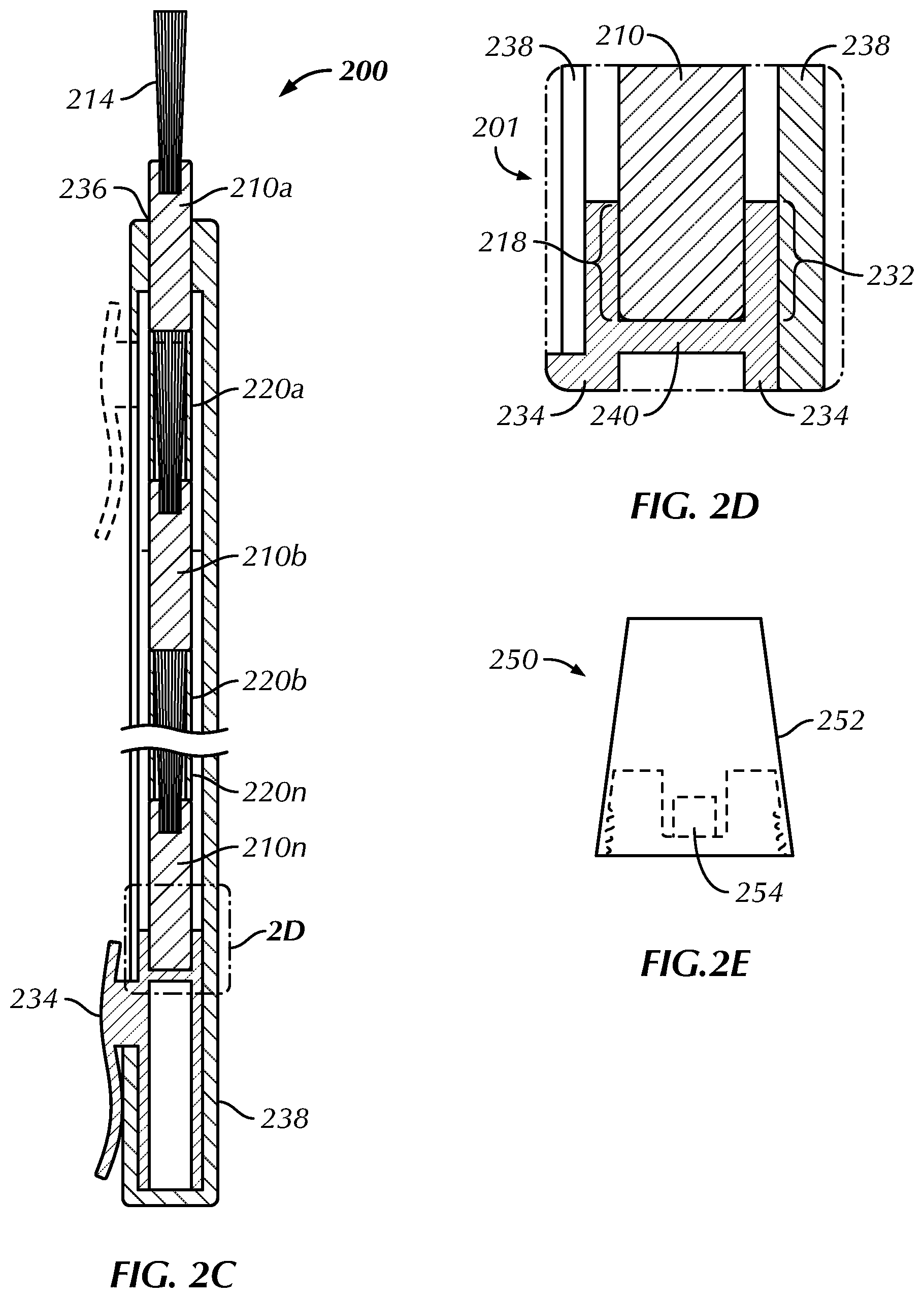
[0036] Referring to FIGS. 2A-2D, a mechanical nail brush apparatus 200 in accordance with a first alternate embodiment of the present invention, is shown. A mechanical nail brush apparatus 200 includes a loadable nail brush 210 and a mechanical dispenser 230. The mechanical dispenser 230 is configured to mechanically dispense one or more loadable nail brushes 210a-210c. The loadable nail brush 210 includes an elongated tubular member 212 having a brush 214 and a connector portion 218 at opposing ends of the loadable nail brush 210. A removable brush cover 220 is arranged and sized to removably fit around and compress the brush 214. The loadable nail brush 210 is configured to be inserted into and detachably connected to the mechanical dispenser 230. However, it is to be understood that the loadable nail brush 210 may be detachably connected to the mechanical dispenser 230 by any means now known or developed in the future.
[0037] FIGS. 2A and 2B depict an embodiment of the mechanical nail brush apparatus 200 of an alternate embodiment of the present invention in respectively an attached arrangement and a detached arrangement. According to this non-limiting embodiment, the mechanical dispenser 230 includes an elongated substantially hollow tubular member 238 having an opening 236 at one end sized to receive one or more loadable nail brushes 210a-210c. The elongated substantially hollow tubular member 238 includes a movable portion 234 configured to slide in a forward and backward direction within a groove along the length of the mechanical dispenser 230. The elongated substantially hollow tubular member 238 also includes a connector portion 232 along an interior portion of the elongated substantially hollow tubular member 238. According to this embodiment of the present invention, the connector portion 232 is flexible configured to frictionally elastically grip the connector portion 218 of the loadable nail brush 210. The loadable nail brush 210 is in contact with a rear wall 240 of the elongated substantially hollow tubular member 238.
[0038] The connector portion 232 is in contact with the movable portion 234 such that any forward and backward movement of the movable portion 234 will also move connector portion 232 within the elongated substantially hollow tubular member 238. According to another embodiment of the present invention, the connector portion 232 is in contact with an end of the connector portion 218 and is configured to push connector portion 218 of the loadable nail brush 210 in a forward or backward direction. However, it is understood that other connections are possible between the connector portion 232 of the elongated substantially hollow tubular member 238 and the connector portion 218 of the loadable nail brush 210 without departing from the scope of the present invention.
[0039] FIG. 2D depicts an enlarged cross-sectional view of a portion of the mechanical nail brush apparatus of FIG. 2C illustrating the connection between the mechanical dispenser and the loadable nail brush. As shown, the connector portion 232 is in contact with the movable portion 234 such that any forward and backward movement of the movable portion 234 will also move connector portion 232 within the elongated substantially hollow tubular member 238. The connector portion 232 movably engages connector portion 218 of the loadable nail brush 210 such that any forward and backward movement of the movable portion 234 will also move connector the loadable nail brush 210 in the same direction. The connector portion 232 is flexible configured to elastically grip the connector portion 218 of the loadable nail brush 210. Operationally, a user can move the movable portion 234 in a forward direction to remove one or more loadable nail brushes 210a-210c thereby replacing the loadable nail brush 210 with another loadable nail brush 210. The user would then remove the removable brush cover 220 in order to apply a nail polish to a nail. The user can move the movable portion 234 in a backward direction to load additional loadable nail brushes 210a-210c. The removable brush cover 220 may be connected to the loadable nail brush 210 by any known means including without limitation friction, a screw mechanism and the like.
[0040] Referring to FIG. 2E, a side view of an optional cap 250 configured to be detachably connected to the loadable nail brush of FIG. 2B, is shown. According to this non-limiting embodiment, the cap 250 includes a lid 252 and a connection member 254. The connection member 254 is configured to be detachably connectable to connector portion 218 of the loadable nail brush 210.
[0041] Referring to FIGS. 3A-3D, a mechanical nail brush apparatus 300 in accordance with a second alternate embodiment of the present invention, is shown. A mechanical nail brush apparatus 300 includes a loadable nail brush 310 and a mechanical dispenser 330. The mechanical dispenser 330 is configured to mechanically dispense one or more loadable nail brushes 310a-310c. The loadable nail brush 310 includes an elongated tubular member 312 having a brush 314 and a connector portion 318 at opposing ends of the loadable nail brush 310. A removable brush cover 320 is arranged and sized to removably fit around and compress the brush 314. The loadable nail brush 310 is configured to be inserted into and detachably connected to the mechanical dispenser 330. However, it is to be understood that the loadable nail brush 310 may be detachably connected to the mechanical dispenser 330 by any means now known or developed in the future.
[0042] FIGS. 3A and 3B depict an embodiment of the mechanical nail brush apparatus 300 of another alternate embodiment of the present invention in respectively an attached arrangement and a detached arrangement. According to this non-limiting embodiment, the mechanical dispenser 330 includes an elongated substantially hollow tubular member 338 having an opening 336 at one end sized to receive one or more loadable nail brushes 310a-310c. The elongated substantially hollow tubular member 338 includes a movable portion 334 configured to slide in a forward and backward direction within a groove along the length of the mechanical dispenser 330. The elongated substantially hollow tubular member 338 also includes a connector portion 332 along an interior portion of the elongated substantially hollow tubular member 338. According to this embodiment of the present invention, the connector portion 332 is flexible configured to frictionally elastically grip the connector portion 318 of the loadable nail brush 310. The loadable nail brush 310 is in contact with a rear wall 340 of the elongated substantially hollow tubular member 338. The loadable nail brush 310 includes a connection member 319 which is mated to a reciprocal connection member 341 extending from the rear wall 340 on the mechanical dispenser 330. The removable brush cover 320 also includes a reciprocal connection member 321 extending therefrom.
[0043] The connector portion 332 is in contact with the movable portion 334 such that any forward and backward movement of the movable portion 334 will also move connector portion 332 within the elongated substantially hollow tubular member 338. According to another embodiment of the present invention, the connector portion 332 is in contact with an end of the connector portion 318 and is configured to push connector portion 318 of the loadable nail brush 310 in a forward or backward direction. However, it is understood that other connections are possible between the connector portion 332 of the elongated substantially hollow tubular member 338 and the connector portion 318 of the loadable nail brush 310 without departing from the scope of the present invention.
[0044] FIG. 3D depicts an enlarged cross-sectional view of a portion of the mechanical nail brush apparatus of FIG. 3C illustrating the connection between the mechanical dispenser and the loadable nail brush. As shown, the connector portion 332 is in contact with the movable portion 334 such that any forward and backward movement of the movable portion 334 will also move connector portion 332 within the elongated substantially hollow tubular member 338. The connector portion 332 movably engages connector portion 318 of the loadable nail brush 310 such that any forward and backward movement of the movable portion 334 will also move connector the loadable nail brush 310 in the same direction. The connector portion 332 is flexible configured to elastically grip the connector portion 318 of the loadable nail brush 310. Operationally, a user can move the movable portion 334 in a forward direction to remove one or more loadable nail brushes 310a-310c thereby replacing the loadable nail brush 310 with another loadable nail brush 310. The connection members 341, 319 and 321 are arranged to connect one or more loadable nail brushes 310a-310c within the mechanical dispenser 330. The user would then remove the removable brush cover 320 in order to apply a nail polish to a nail. The user can move the movable portion 334 in a backward direction to load additional loadable nail brushes 310a-310c. The removable brush cover 320 may be connected to the loadable nail brush 310 by any known means including without limitation friction, a screw mechanism and the like.
[0045] Referring to FIG. 3E, a side view of an optional cap 350 configured to be detachably connected to the loadable nail brush of FIG. 3B, is shown. According to this non-limiting embodiment, the cap 350 includes a lid 352 and a connection member 354. The connection member 354 is configured to be detachably connectable to connector portion 318 of the loadable nail brush 310.
[0046] Referring to FIGS. 4A-4D, a mechanical nail brush apparatus 400 in accordance with yet another alternate embodiment of the present invention, is shown. A mechanical nail brush apparatus 400 includes a loadable nail brush 410 and a mechanical dispenser 430. The mechanical dispenser 430 is configured to mechanically dispense one or more loadable nail brushes 410a-410c. The loadable nail brush 410 includes an elongated tubular member 412 having a brush 414 and a connector portion 418 at opposing ends of the loadable nail brush 410. A removable brush cover 420 is arranged and sized to removably fit around and compress the brush 414. The loadable nail brush 410 is configured to be inserted into and detachably connected to the mechanical dispenser 430. However, it is to be understood that the loadable nail brush 410 may be detachably connected to the mechanical dispenser 430 by any means now known or developed in the future.
[0047] FIGS. 4A and 4B depict an embodiment of the mechanical nail brush apparatus 400 of an alternate embodiment of the present invention in respectively an attached arrangement and a detached arrangement. According to this non-limiting embodiment, the mechanical dispenser 430 includes an elongated substantially hollow tubular member 438 having an opening 436 at one end sized to receive one or more loadable nail brushes 410a-410c. The elongated substantially hollow tubular member 438 includes a rotatable portion 444 configured to engage a screw mechanism 442 to move the loadable nail brushes 410a-400c in a forward and backward direction along the length of the mechanical dispenser 430. The elongated substantially hollow tubular member 438 also includes a connector portion 432 along an interior portion of the elongated substantially hollow tubular member 438. According to this embodiment of the present invention, the connector portion 432 is flexible configured to frictionally elastically grip the connector portion 418 of the loadable nail brush 410. The loadable nail brush 410 is in contact with a rear wall 440 of the elongated substantially hollow tubular member 438.
[0048] The connector portion 432 is in contact with the movable portion 434 such that any forward and backward movement of the movable portion 434 will also move connector portion 432 within the elongated substantially hollow tubular member 438. According to another embodiment of the present invention, the connector portion 432 is in contact with an end of the connector portion 418 and is configured to push connector portion 418 of the loadable nail brush 410 in a forward or backward direction. However, it is understood that other connections are possible between the connector portion 432 of the elongated substantially hollow tubular member 438 and the connector portion 418 of the loadable nail brush 410 without departing from the scope of the present invention.
[0049] FIG. 4D depicts an enlarged cross-sectional view of a portion of the mechanical nail brush apparatus of FIG. 4C illustrating the connection between the mechanical dispenser and the loadable nail brush. As shown, the connector portion 432 is in contact with the movable portion 434 such that any forward and backward movement of the movable portion 434 will also move connector portion 432 within the elongated substantially hollow tubular member 438. The connector portion 432 movably engages connector portion 418 of the loadable nail brush 410 such that any forward and backward movement of the movable portion 434 will also move connector the loadable nail brush 410 in the same direction. The connector portion 432 is flexible configured to elastically grip the connector portion 418 of the loadable nail brush 410. Operationally, a user can move the movable portion 434 in a forward direction to remove one or more loadable nail brushes 410a-410c thereby replacing the loadable nail brush 410 with another loadable nail brush 410. The user would then remove the removable brush cover 420 in order to apply a nail polish to a nail. The user can move the movable portion 434 in a backward direction to load additional loadable nail brushes 410a-410c. The removable brush cover 420 may be connected to the loadable nail brush 410 by any known means including without limitation friction, a screw mechanism and the like.
[0050] Referring to FIG. 4E, a side view of an optional cap 450 configured to be detachably connected to the loadable nail brush of FIG. 4B, is shown. According to this non-limiting embodiment, the cap 450 includes a lid 452 and a connection member 454. The connection member 454 is configured to be detachably connectable to connector portion 418 of the loadable nail brush 410.
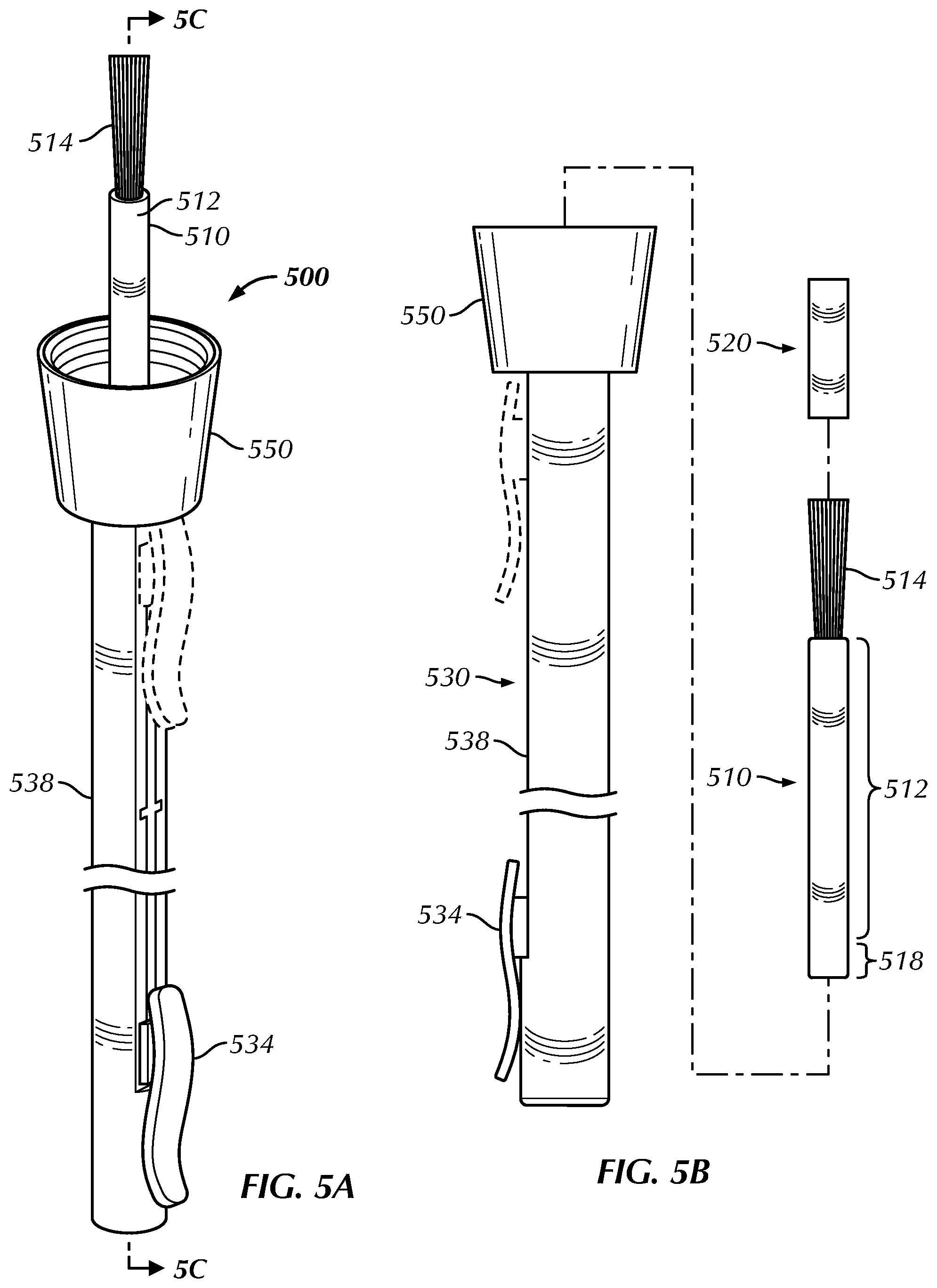
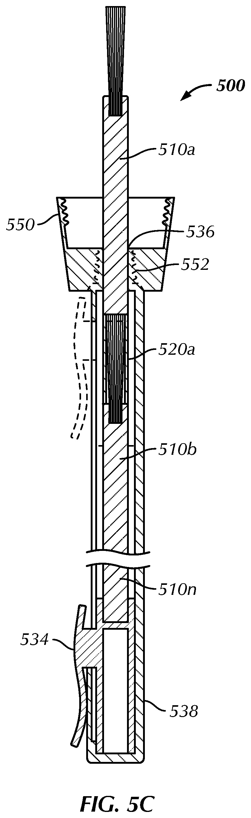
[0051] Referring to FIGS. 5A-5C, a mechanical nail brush apparatus 500 in accordance with a fourth embodiment of the present invention, is shown. A mechanical nail brush apparatus 500 includes a loadable nail brush 510 and a mechanical dispenser 530. The mechanical dispenser 530 is configured to mechanically dispense one or more loadable nail brushes 510. The loadable nail brush 510 includes an elongated tubular member 512 having a brush 514 and a connector portion 518 at opposing ends of the loadable nail brush 510. The elongated tubular member 512 may be composed of, without limitation, plastic, polyvinyl chloride, polyethylene, polypropylene, carbon fiber, glass, metal, wood and the like. A removable brush cover 520 is arranged and sized to removably fit around and compress the brush 514. The removable brush cover 520 may be composed of, without limitation, plastic, polyvinyl chloride, polyethylene, polypropylene, carbon fiber, paper, cardboard, rubber and the like. The loadable nail brush 510 is configured to be inserted into and detachably connected to the mechanical dispenser 530. However, it is to be understood that the loadable nail brush 510 may be detachably connected to the mechanical dispenser 530 by any means now known or developed in the future. The brush 514 is configured to be used to apply a nail polish to a user's fingernail or toenail in an operational mode.
[0052] FIGS. 5A and 5B depict an embodiment of the mechanical nail brush apparatus 500 of an embodiment of the present invention in respectively an attached arrangement and a detached arrangement. According to this non-limiting embodiment, the mechanical dispenser 530 includes an elongated substantially hollow tubular member 538 having an opening 536 at one end sized to receive one or more loadable nail brushes 510. The elongated substantially hollow tubular member 538 includes a detachable cap 550. The detachable cap 550 may be integrated into hollow tubular member 538 or detachable via an optional screw mechanism 552. It is understood that the detachable cap 550 may be combined with any of the embodiments of the present invention. The elongated substantially hollow tubular member 538 includes a movable portion 534 configured to slide in a forward and backward direction within a groove along the length of the mechanical dispenser 530. The elongated substantially hollow tubular member 538 also includes a connector portion along an interior portion of the elongated substantially hollow tubular member 538. According to this embodiment of the present invention, the connector portion is flexible with one more ridge configured to elastically grip respective one or ridge on the connector portion 518 of the loadable nail brush 510. The connector portion is in contact with the movable portion 534 such that any forward and backward movement of the movable portion 534 will also move connector portion within the elongated substantially hollow tubular member 538. According to another embodiment of the present invention, the connector portion 538 is in contact with an end of the connector portion 518 and is configured to push connector portion 518 of the loadable nail brush 510 in a forward or backward direction. However, it is understood that other connections are possible between the connector portion of the elongated substantially hollow tubular member 538 and the connector portion 518 of the loadable nail brush 510 without departing from the scope of the present invention.
[0053] Referring to FIG. 6, a mechanical nail brush apparatus 600 in accordance with yet another alternate embodiment of the present invention, is shown. A mechanical nail brush apparatus 600 includes a loadable nail brush 610 and a mechanical dispenser 630. The mechanical dispenser 630 includes an elongated substantially hollow tubular member 138 having an opening at one end sized to receive one or more loadable nail brushes 610. The elongated substantially hollow tubular member 638 includes a movable portion 634 configured to slide in a forward and backward direction within a groove along the length of the mechanical dispenser 630. The elongated substantially hollow tubular member 638 also includes elastomer 639. Elastomer 639 may be comprised of any elastic material including without limitation any polymer, resin, natural rubber, neoprene rubber, buna-s, buna-n and the like. The loadable nail brush 610 includes an elongated tubular member 612 having a brush 614 and a connector portion (not shown) at opposing ends of the loadable nail brush 410. A removable brush cover (not shown) is arranged and sized to removably fit around and compress the brush 614. The loadable nail brush 610 is configured to be inserted into and detachably connected to the mechanical dispenser 630. However, it is to be understood that the loadable nail brush 610 may be detachably connected to the mechanical dispenser 630 by any means now known or developed in the future.
[0054] It will be apparent to those skilled in the art that various modifications and variations can be made in the system and method of the present invention without departing form the spirit or scope of the invention. Thus, it is intended that the present invention cover the modifications and variations of the invention provided they come within the scope of the appended claims and their equivalents.
[0055] Obviously, many other modifications and variations of the present invention are possible in light of the above teachings. The specific embodiments discussed herein are merely illustrative, and are not meant to limit the scope of the present invention in any manner. It is therefore to be understood that within the scope of the disclosed concept, the invention may be practiced otherwise than as specifically described.
* * * * *
D00000
D00001
D00002
D00003
D00004
D00005
D00006
D00007
D00008
D00009
D00010
D00011
XML
uspto.report is an independent third-party trademark research tool that is not affiliated, endorsed, or sponsored by the United States Patent and Trademark Office (USPTO) or any other governmental organization. The information provided by uspto.report is based on publicly available data at the time of writing and is intended for informational purposes only.
While we strive to provide accurate and up-to-date information, we do not guarantee the accuracy, completeness, reliability, or suitability of the information displayed on this site. The use of this site is at your own risk. Any reliance you place on such information is therefore strictly at your own risk.
All official trademark data, including owner information, should be verified by visiting the official USPTO website at www.uspto.gov. This site is not intended to replace professional legal advice and should not be used as a substitute for consulting with a legal professional who is knowledgeable about trademark law.