Joint Finger Ring
TAN; Bowen
U.S. patent application number 17/060200 was filed with the patent office on 2021-01-21 for joint finger ring. The applicant listed for this patent is Bowen TAN. Invention is credited to Bowen TAN.
| Application Number | 20210015221 17/060200 |
| Document ID | / |
| Family ID | 1000005132604 |
| Filed Date | 2021-01-21 |


| United States Patent Application | 20210015221 |
| Kind Code | A1 |
| TAN; Bowen | January 21, 2021 |
JOINT FINGER RING
Abstract
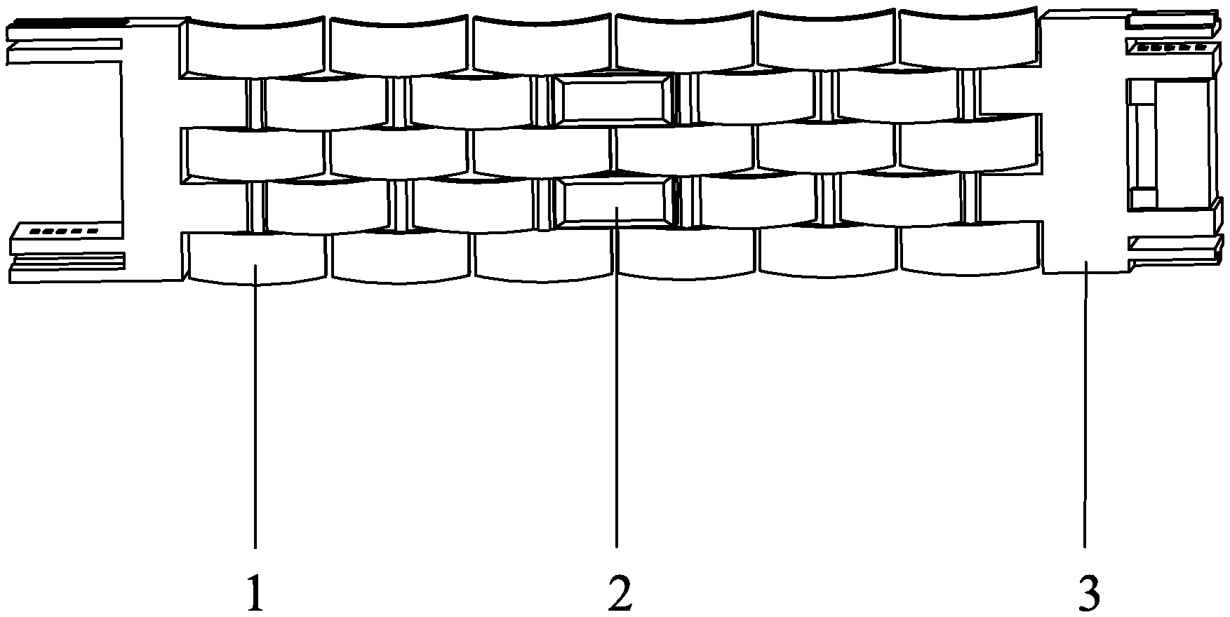
The innovative product is a joint finger ring, particularly refers to a finger ring capable of being spliced, assembled, bent and adjusted, and relates to the technical field of ornamental finger rings and watchbands. A joint finger ring is composed of a ring setting (1), inlays (2) and connection components (3), wherein the inlays (2) are arranged in the ring setting (1). The left end and the right end of the ring setting (1) are movably connected through the connection components (3). The utility model solves the problem that in the wearing process of the traditional finger ring, the size of the finger ring of a favorite style is appropriately increased to fit the finger, and consequently, it is impossible to achieve the best feeling when people wear the finger ring, and especially for the characteristics of the male finger bones, the finger ring cannot be taken off.
| Inventors: | TAN; Bowen; (SHANGHAI, CN) | ||||||||||
| Applicant: |
|
||||||||||
|---|---|---|---|---|---|---|---|---|---|---|---|
| Family ID: | 1000005132604 | ||||||||||
| Appl. No.: | 17/060200 | ||||||||||
| Filed: | October 1, 2020 |
Related U.S. Patent Documents
| Application Number | Filing Date | Patent Number | ||
|---|---|---|---|---|
| PCT/CN2018/093810 | Jun 29, 2018 | |||
| 17060200 | ||||
| Current U.S. Class: | 1/1 |
| Current CPC Class: | A44C 9/0046 20130101; A44C 9/02 20130101 |
| International Class: | A44C 9/00 20060101 A44C009/00; A44C 9/02 20060101 A44C009/02 |
Claims
1. A joint finger ring, comprising a ring setting (1), inlays (2) and connection components (3), wherein the inlays (2) are embedded into inlay wrapping materials to form an integral module to be arranged in the ring setting (1), and the left end and the right end of the ring setting (1) are movably connected through the connection components (3); the ring setting (1) is similar to a watchband and can be bent, disassembled and assembled, and is composed of ring setting components (21), novel C-shaped pins (22) and C-shaped pipes (23) or fixed pins (24) and fixed caps (25).
2. The joint finger ring according to claim 1, wherein the ring setting components (21) are made of precious metals such as gold, platinum, silver or ordinary metals or wooden materials, ceramic materials, clay materials, jadeite, Hetian jade materials, Shoushan stones, marble materials or purple sands and is structurally composed of a ring setting component (21-1), a ring setting component (21-2) and a ring setting component (21-3), wherein the ring setting component (21-1) is entirely perforated from top to bottom and correspondingly connected with the fixed pin and fixed cap; the ring setting component (21-2) is combined with the fixed pin and has T-shaped chucks; the ring setting component (21-3) is internally provided with T-shaped rails, which are correspondingly connected with the T-shaped chucks in the ring setting component (21-2).
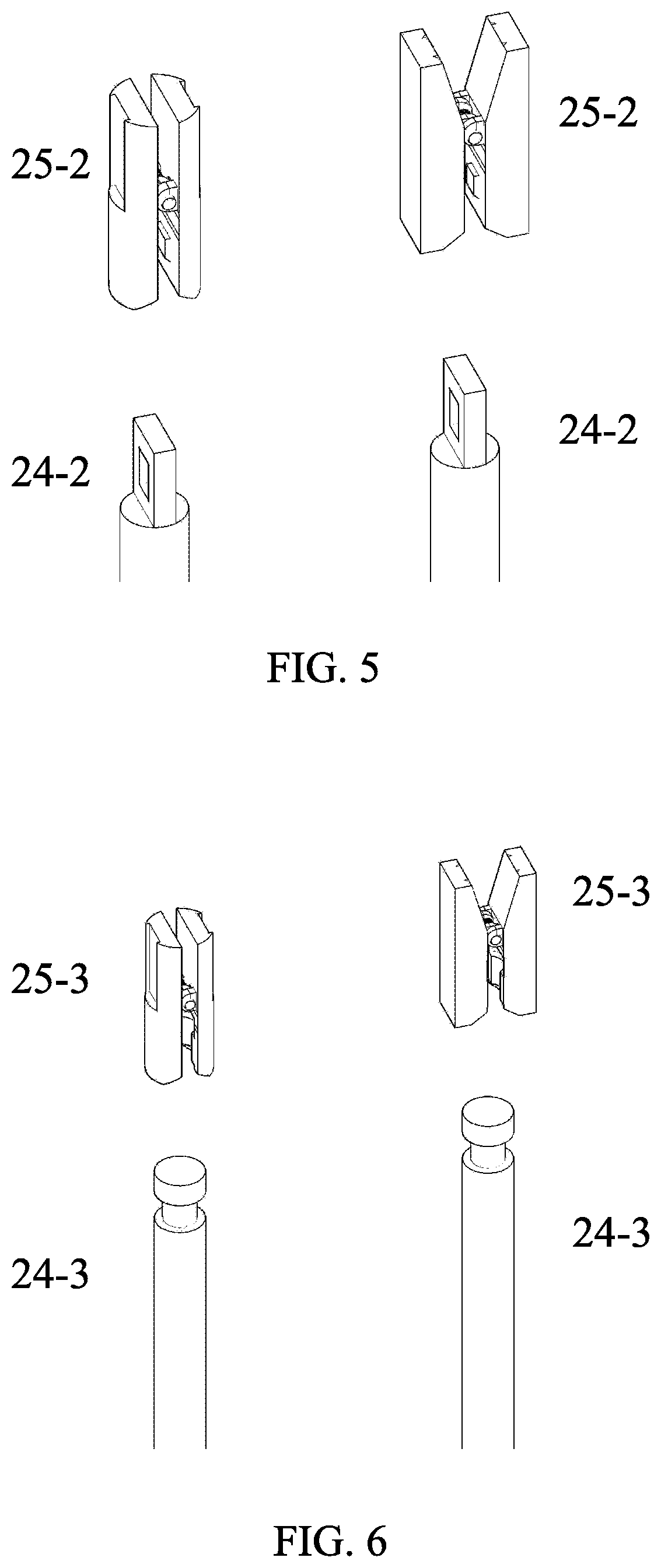
3. The joint finger ring according to claim 1, wherein for the fixed pin (24); wherein the head of the fixed pin (24-1) has two outwardly-bulged fixed pin bayonets which are correspondingly connected with slots of the fixed cap (25-1) through the elasticity of the metal, the tail appearance corresponds to the appearance structure of the fixed cap, and the diameter is greater than the fixed pin; the head of the fixed pin (24-2) has a hollow slot correspondingly connected with the fixed cap (25-2), the tail appearance corresponds to the appearance structure of the fixed cap, and the diameter is greater than the fixed pin; the head of the fixed pin (24-3) is a cylindrical bayonet correspondingly connected with a concave annular slot of the fixed cap (25-3), the tail appearance corresponds to the appearance structure of the fixed cap, and the diameter is greater than the fixed pin.
4. The joint finger ring according to claim 1, wherein for the fixed cap (25); wherein the fixed cap (25-1) is hollow and similar to a cap structure, and an internal slot corresponding to the bayonet of the fixed pin (24-1) is arranged close to the top end; the fixed cap (25-2) has the appearance and function similar to a clip, and has a bulged bayonet corresponding to the slot of the fixed pin (24-2) at the tail; the fixed cap (25-3) has the appearance similar to the clip and has a concave annular slot corresponding to the cylindrical bayonet of the fixed pin (24-3) at the tail.
5. The joint finger ring according to claim 1, wherein the inlays (2) are embedded into the inlay wrapping materials to form the integral module to be arranged in the ring setting (1).
6. The joint finger ring according to claim 1, wherein the connection component (3) is composed of a module A and a module B to form movable connection.
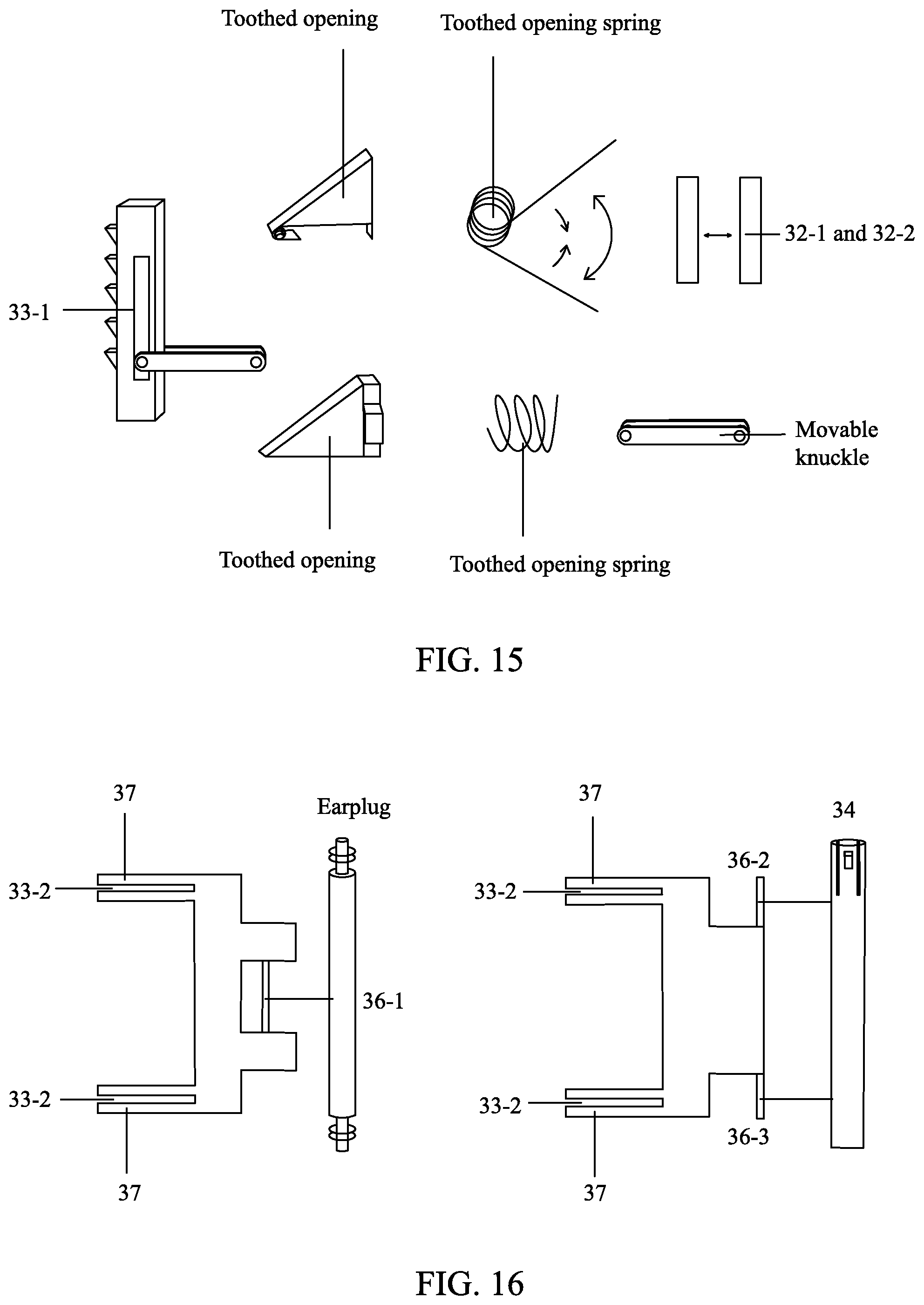
7. The joint finger ring according to claim 3, wherein the module A comprises a lock switch button (31), a return spring (32), module A joint bayonets (33-1), a fixed bulge or notch (34), a module A ring setting joint (35-1) or a module A ring setting joint (35-2) and a module A ring setting joint (35-3); wherein the lock switch button (31) used for movably separating the module A and the module B is located on the middle position of the whole module A; the return spring (32) is located right below the tail of the module A lock switch button (31); the module A joint bayonets (33-1) are located at two sides of the lock switch button (31), and the module A joint bayonet (33-1) is composed of a toothed opening, a toothed opening spring, a toothed opening carrier rod and a movable knuckle, wherein the toothed opening is located in the toothed opening carrier rod and is a row of triangular movable exposed bayonets; the toothed opening spring is located in the toothed opening and connected with the toothed opening spring and the toothed opening carrier rod through a barrel-shaped hollow column on the front end; the movable knuckle is located between the lock switch button (31) and the toothed opening carrier rod; one end is connected with the lock switch button (31), and one end is connected with the toothed opening carrier rod; the toothed opening carrier rod is connected with the lock switch button (31) through the movable knuckle, and the movable knuckle is perpendicular to a position between the toothed opening carrier rod and the lock switch button (31); the fixed bulge or notch (34) is located on the left end and the right end of the module A and corresponds to the fixed notch or bulge (37) in the module B; the ring setting joint (35-1) is connected with one end of the ring setting through an earplug; the ring setting joint (35-2) and the ring setting joint (35-3) are connected with the front end of the fixed pin (24) and fixedly connected with one end of the ring setting through the fixed cap; the module B comprises module B joint bayonets (33-2), a module B ring setting joint (36-1) or a module B ring setting joint (36-2), a module B ring setting joint (36-3) and a fixed notch or bulge (37); wherein the module B joint bayonets (33-2) are located on two cuboids at the upper inner sides of the module B, the cuboid internally comprises a row of exposed triangular recesses; and the triangular recesses are correspondingly connected with the toothed opening in the module A joint bayonets (33-1); the fixed notch or bulge (37) is located on the left end and the right end of the module B and corresponds to the fixed bulge or notch (34) in the module A; the module B ring setting joint (36-1) is located on the lower end of the module B and connected with one end of the ring setting through the earplug, or the module B ring setting joint (36-2) and the module B ring setting joint (36-3) are located at two lower sides of the module B and connected with one end of the ring setting through the fixed caps.
8. The joint finger ring according or the joint finger ring according to claim 3, wherein the module A comprises a lock switch button (31), a return magnet (32-1), a return magnet (32-2), a module A joint bayonet (33-1), a fixed opening (34), a module A ring setting joint (35-1) or a module A ring setting joint (35-12) and a module A ring setting joint (35-3); wherein the lock switch button (31) used for movably separating the module A and the module B is located on the middle position of the whole module A; the return magnet (32-1) is located inside the module A lock switch button (31) and plays a role in repelling the return magnet (32-2) because of like polarities; the return magnet (32-2) is located in the middle part of the module A and plays a role in repelling the return magnet (32-1) because of like polarities; the module A joint bayonets (33-1) are located at two sides of the lock switch button (31), and the module A joint bayonet (33-1) is composed of a toothed opening, a toothed opening return magnet (1), a toothed opening return magnet (2), a toothed opening carrier rod and a movable knuckle, wherein the toothed opening is located in the toothed opening carrier rod and is a row of triangular movable exposed bayonets, and the toothed opening return magnet (1) is located at the rear end of the toothed opening and returns the toothed opening according to the principle that like polarities repel each other; the movable knuckle is located between the lock switch button (31) and the toothed opening carrier rod; one end is connected with the lock switch button (31), and one end is connected with the toothed opening carrier rod; the toothed opening carrier rod is connected with the lock switch button (31) through the movable knuckle, and the movable knuckle is perpendicular to a position between the toothed opening carrier rod and the lock switch button (31); the fixed bulge or notch (34) is located on the left end and the right end of the module A and corresponds to the fixed notch or bulge (37) in the module B; the ring setting joint (35-1) is connected with one end of the ring setting through an earplug; the ring setting joint (35-2) and the ring setting joint (35-3) are connected with the front end of the fixed pin (24) and fixedly connected with one end of the ring setting through the fixed cap; the module B comprises module B joint bayonets (33-2), a module B ring setting joint (36-1) or a module B ring setting joint (36-2), a module B ring setting joint (36-3) and a fixed notch or bulge (37); wherein the module B joint bayonets (33-2) are located on two cuboids at the upper inner sides of the module B, the cuboid internally comprises a row of exposed triangular recesses; and the triangular recesses are correspondingly connected with the toothed opening in the module A joint bayonets (33-1); the fixed notch or bulge (37) is located on the left end and the right end of the module B and corresponds to the fixed bulge or notch (34) in the module A; the module B ring setting joint (36-1) is located on the lower end of the module B and connected with one end of the ring setting through the earplug, or the module B ring setting joint (36-2) and the module B ring setting joint (36-3) are located at two lower sides of the module B and connected with one end of the ring setting through the fixed caps.
Description
CROSS-REFERENCE TO RELATED APPLICATIONS
[0001] This application is a continuation of International Patent Application No. PCT/CN2018/093810 with a filing date of Jun. 29, 2018, designating the United States, now pending.
TECHNICAL FIELD
[0002] The innovative product relates to the technical field of ornamental finger rings and watchbands, and particularly relates to a spliceable, assemblable, bendable and adjustable joint finger ring.
BACKGROUND
[0003] At least in modern times, most of finger rings in the jewelry market have different appearances, but most of them are always fixed circular finger rings. Although the size of each finger ring is optional at the beginning of the purchase, the finger ring is inevitable to pass through finger joints during a wearing process. Therefore, the size of the finger ring may be appropriately increased at the beginning of production to fit the finger. As a result, it is impossible to achieve the best feeling when people wear the finger ring; and moreover, due to a lot of reasons, the finger ring may not be taken off, which is more obvious especially for the characteristics of male finger bones. Moreover, most of the finger rings cannot change their appearances after being bought, which is mainly reflected in the fact that when consumers want to buy products of the same style with different inlays, they must buy the same products again besides the inlays.
SUMMARY
[0004] The purpose of the innovative product is to overcome the defects and disadvantages of the prior art and provide a joint finger ring. The whole structure of the finger ring is composed of three parts: one is a ring setting, wherein the ring setting is a main integral part of this type of finger rings, and various jewelries, inlays and appearances of the ring setting can be changed through the modular disassembling and assembling of components of the ring setting. The second is, ring plane inlays, which play a role in adding a finishing touch to make the appearance beautiful. The ring plane inlays are embedded into inlay wrapping materials to form an integral module to achieve an modular disassembling and assembling effect, so that the inlays, the appearances of the inlays or the overall appearance of the finger ring can be appropriately adjusted. The third is connection components which movably connect two ends of the ring setting. Through finely-adjustable connection module, the finger ring can be comfortably worn onto the finger.
[0005] The joint finger ring is composed of a ring setting, inlays and connection components, wherein the inlays are arranged on the ring setting through inlay wrapping materials, and the left end and the right end of the ring setting are movably connected through the connection components. With a structure similar to a component structure of a watchband, various functions such as splicing, bending, disassembling, assembling and adjusting can be realized.
[0006] The ring setting is similar to a watchband, and capable of being bent, disassembled and assembled and can adjust the appearance of the ring setting. The ring setting is composed of ring setting components, novel C-shaped pins and C-shaped pipes or fixed caps and fixed pins. The structure of the ring setting can be disassembled and assembled in a modularization manner, so that the appearance adjustability of the ring setting can be realized. The ring setting is made of precious metals such as gold, platinum, silver or ordinary metals or wooden materials, ceramic materials, clay materials, jadeite, Hetian jade materials, Shoushan stone materials, marble materials or purple sands.
[0007] The inlay is a part to beautify the appearance of the ring setting. Compared with the previous process of directly embedding the inlays into the ring setting, this type of finger rings can be freely disassembled and assembled by inserting the inlays into the inlay wrapping materials in advance, thereby achieving the appropriate adjustment of the appearance of the ring setting.
[0008] Each of the connection components is composed of a module A and a module B to form functions of movable connection and fine adjustment, which incorporates the design concepts of ergonomics, overall aesthetics, ultra-thin standards, convenient use, and feasible craftsmanship.
DESCRIPTION OF THE DRAWINGS
[0009] FIG. 1 is a structural schematic diagram of a joint finger ring of the utility model;
[0010] FIG. 2 is a plan of fixed caps and fixed pins of embodiments;
[0011] FIG. 3 is three-dimensional schematic diagram of fixed caps and fixed pins of embodiments;
[0012] FIG. 4 is a structural three-dimensional schematic diagram of fixed the pin 24-1 and the fixed cap 25-1 of embodiments;
[0013] FIG. 5 is a structural three-dimensional schematic diagram of fixed the pin 24-2 and the fixed cap 25-2 of embodiments;
[0014] FIG. 6 is a structural three-dimensional schematic diagram of fixed the pin 24-3 and the fixed cap 25-3 of embodiments;
[0015] FIG. 7 is a structural three-dimensional schematic diagram of a ring setting component 21 and an inlay wrapping material of embodiments;
[0016] FIG. 8 is a three-dimensional schematic diagram of an assembling mode I of a ring setting of embodiments;
[0017] FIG. 9 is a three-dimensional schematic diagram of an assembling mode II of the ring setting of embodiments;
[0018] FIG. 10 is a schematic diagram showing the formation of an integral module of embodiments;
[0019] FIG. 11 is schematic diagram showing an appearance of the ring setting of embodiments;
[0020] FIG. 12 is a schematic diagram showing a junction position of the module A and the module B on the ring setting of the embodiments;
[0021] FIG. 13 is a schematic diagram of an internal structure of the module A of the embodiments;
[0022] FIG. 14 is a schematic diagram of internal components of the module A of the embodiments;
[0023] FIG. 15 is a schematic diagram of internal components of a carrier rod of the embodiments;
[0024] FIG. 16 is a structural schematic diagram of the module B of the embodiments;
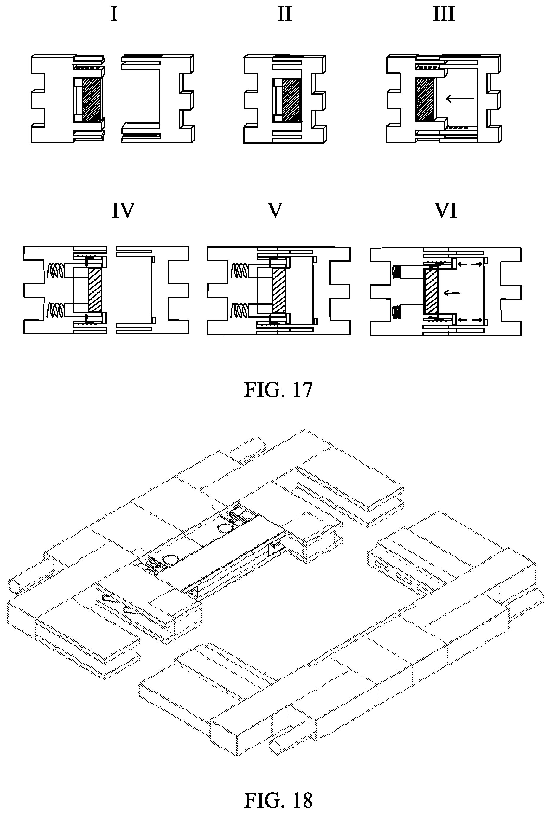
[0025] FIG. 17 is a structural schematic diagram showing the connection and disconnection between the module A and the module B of the embodiments;
[0026] FIG. 18 is a front view of the appearance of the module A of the embodiments;
[0027] and
[0028] FIG. 19 is a front view of the appearance of the module B of the embodiments.
DETAILED DESCRIPTION OF PREFERRED EMBODIMENTS
[0029] The utility model is further described below in combination with the drawings and embodiments.
[0030] A joint finger ring (as shown in FIG. 1) is composed of a ring setting 1, inlays 2 and connection components 3, wherein the inlays 2 are embedded into inlay wrapping materials to form an integral module to be arranged into the ring setting 1. The left end and the right end of the ring setting 1 are movably connected through the connection components 3.
[0031] The ring setting 1 is similar to a watchband and can be bent, disassembled and assembled. The ring setting is composed of ring setting components 21, novel C-shaped pins 22 and C-shaped pipes 23 or fixed pins 24 and fixed caps 25.
[0032] The fixed pin 24 can be correspondingly connected with the fixed cap 25. Through the innovative design of the internal structure, the function for fixing the ring components and the function for easily adjusting the appearance (as shown in FIG. 2-FIG. 6) can be realized.
[0033] The fixed cap 25 can be correspondingly connected with the fixed pin 24. Through the innovative design of the internal structure, the function for fixing the ring components and the function for easily adjusting the appearance (as shown in FIG. 2-FIG. 6) can be realized.
[0034] The ring setting components 21 are modular components that can be disassembled and assembled into the appearance of the ring setting 1 (as shown in FIG. 7-FIG. 9).
[0035] The inlays are embedded into the inlay wrapping materials to form the integral module to be arranged in the ring setting 1 (as shown in FIG. 8-FIG. 10).
[0036] The connection component 3 is composed of a module A and a module B to form the movable connection (as shown in FIG. 12 and FIG. 17-FIG. 19).
[0037] In the joint finger ring, the module A includes a lock switch button 31, a return spring 32 or a return magnet 32-1 and a return magnet 32-2, module A joint bayonets 33-1, a fixed bulge or notch 34, a module A ring setting joint 35-1 or 35-2 and 35-3 (as shown in FIG. 13).
[0038] The return spring 32 or the return magnet 32-1 and the return magnet 32-2 are located right below the tail of the module A lock switch button 31 (as shown in FIG. 13).
[0039] The module A joint bayonets 33-1 are located at two sides of the lock switch button 31. The module A joint bayonet 33-1 is composed of a toothed opening, a toothed opening spring or a toothed opening return magnet 1, a toothed opening carrier rod and a movable knuckle (as shown in FIG. 13).
[0040] The toothed opening is located in the toothed opening carrier rod and is a row of triangular movable exposed bayonets.
[0041] The toothed opening carrier rod is connected with the lock switch button 31 through the movable knuckle. The movable knuckle is perpendicular to a position between the toothed opening carrier rod and the lock switch button 31 (as shown in FIG. 14-FIG. 15).
[0042] The fixed bulge or notch 34 is located on the left end and the right end of the module A and is used for the up-down fixation of the module A and the module B at a connection state correspondingly together with the fixed notch or bulge 37 in the module B.
[0043] The module A passes through the ring setting joint 35-1 to be connected with one end of the ring setting through an earplug or the module A is connected with one end of the ring setting through the connection of the ring setting joint 35-2 and the ring setting joint 35-32 and the fixed pin 34 and the fixed cap 35 (as shown in FIG. 13).
[0044] Functions of Components:
[0045] When the module A and the module B are correspondingly connected by a user, under the interaction of three components, i.e. the toothed opening, the toothed opening spring and the module B joint bayonets 33-2, the finger ring can be worn on the finger; and when the module A and the module B are separated by the user, the lock switch button 31 is pressed down; after the toothed opening carrier rod is pulled towards the inner side through the movable knuckle, the toothed opening is separated from a slot in the module B joint bayonets 33-2, thereby separating the module A and the module B (as shown in FIG. 17).
[0046] Before the wearing (referring to I and IV in FIG. 17): the components in the module A and the module B are on fixed positions.
[0047] During the wearing (referring to II and V in FIG. 17): the first joint bayonet 33-1 on the front end of the module A is connected with a connection position of the second joint bayonet 33-2 on the front end of the module B.
[0048] In this process, the exposed toothed opening of the module A may be continuously pushed by the module A joint bayonets 33-2 to have a telescopic motion so as to be fixed in the longitudinal direction. At the same time, the fixed bulge or notch 34 in the module A is correspondingly connected with the fixed notch or bulge 37 in the module B so as to fix the module A in the vertical direction and to adjust the feeling to the best state.
[0049] The toothed opening is under the action of the toothed opening spring or the toothed opening return magnet 1. Through the toothed opening spring or the toothed opening return magnet 1, the triangular slot on the connection position of the joint bayonets 33-2 in the module B can be correspondingly connected with the toothed opening along with the connection action.
[0050] After the wearing (referring to II in FIG. 17): the module A and the module B are correspondingly connected in the vertical and longitudinal directions, and each component in the module A is returned.
[0051] During the separation (referring to III and VI in FIG. 17): the lock switch button 31 is pushed backwards first, and at this moment, the exposed toothed opening may be retracted inwards, so that the module A and the module B have no fixed connection in the longitudinal direction.
[0052] After the separation: each component in the module A is returned.
[0053] In conclusion, this innovative design solves the problem that in the wearing process of the traditional finger rings, the size of the finger ring of the favorite style is appropriately increased at the beginning of selection or customization so as to fit the finger. As a result, it is impossible to achieve the best feeling when people wear the finger ring; and moreover, due to a lot of reasons, the finger ring may not be taken off, which is more obvious especially for the characteristics of male finger bones. Meanwhile, when the consumer needs the product of the same style with different appearances, only the corresponding accessories need to be added, so that the trouble for purchasing the whole product with the original structure can be avoided. Based on the market demand, this design incorporates the design concepts of ergonomics, overall aesthetics, ultra-thin standards, convenient use and feasible craftsmanship. The innovative design is made on the basis of the traditional concept of the existing finger ring, thereby providing technical and material basis to fill a gap in the market.
* * * * *
D00000
D00001
D00002
D00003
D00004
D00005
D00006
D00007
D00008
D00009
D00010
XML
uspto.report is an independent third-party trademark research tool that is not affiliated, endorsed, or sponsored by the United States Patent and Trademark Office (USPTO) or any other governmental organization. The information provided by uspto.report is based on publicly available data at the time of writing and is intended for informational purposes only.
While we strive to provide accurate and up-to-date information, we do not guarantee the accuracy, completeness, reliability, or suitability of the information displayed on this site. The use of this site is at your own risk. Any reliance you place on such information is therefore strictly at your own risk.
All official trademark data, including owner information, should be verified by visiting the official USPTO website at www.uspto.gov. This site is not intended to replace professional legal advice and should not be used as a substitute for consulting with a legal professional who is knowledgeable about trademark law.