Geothermal Development System And The Construction Method Thereof
TANG; Chunan ; et al.
U.S. patent application number 17/040897 was filed with the patent office on 2021-01-14 for geothermal development system and the construction method thereof. The applicant listed for this patent is DALIAN MECHSOFT CO., LTD, DALIAN UNIVERSITY OF TECHNOLOGY, MECHSOFTTECHNOLOGY (U.S.A.) CO., LLC. Invention is credited to Tianhui MA, Chunan TANG, Mu TANG, Sijing WANG, Juying YANG, Jian ZHAO.
| Application Number | 20210010718 17/040897 |
| Document ID | / |
| Family ID | 1000005146524 |
| Filed Date | 2021-01-14 |

| United States Patent Application | 20210010718 |
| Kind Code | A1 |
| TANG; Chunan ; et al. | January 14, 2021 |
GEOTHERMAL DEVELOPMENT SYSTEM AND THE CONSTRUCTION METHOD THEREOF
Abstract
A geothermal development system includes a ground lifting system, a large-diameter shaft, an underground high temperature and high pressure heat transfer pool, a heat transfer diversion channel, a hot mine blasting fracture reservoir formed by an inlet blasting tunnel and a main tunnel, and a removable sealing device. The injection pipe and the collection pipe are set along the large diameter silo wall in the geothermal development system. The injection pipe is connected to the collection pipe through the heat transfer diversion channel in the dry hot rock. The circulation main roadway is arranged around the underground high temperature and high pressure heat transfer pool. Multiple blasting roadways are set along the main roadway level to form hot mine blasting fracture reservoir with loose blasting by caving method. A movable sealing device is arranged above the blasting layer of the large-diameter shaft.
| Inventors: | TANG; Chunan; (Dalian, Liaoning, CN) ; ZHAO; Jian; (Dalian, Liaoning, CN) ; YANG; Juying; (Dalian, Liaoning, CN) ; MA; Tianhui; (Dalian, Liaoning, CN) ; WANG; Sijing; (Dalian, Liaoning, CN) ; TANG; Mu; (Dalian, Liaoning, CN) | ||||||||||
| Applicant: |
|
||||||||||
|---|---|---|---|---|---|---|---|---|---|---|---|
| Family ID: | 1000005146524 | ||||||||||
| Appl. No.: | 17/040897 | ||||||||||
| Filed: | January 12, 2019 | ||||||||||
| PCT Filed: | January 12, 2019 | ||||||||||
| PCT NO: | PCT/CN2019/071502 | ||||||||||
| 371 Date: | September 23, 2020 |
| Current U.S. Class: | 1/1 |
| Current CPC Class: | E21B 7/046 20130101; F24T 10/30 20180501; F24T 10/20 20180501; F24T 10/15 20180501 |
| International Class: | F24T 10/30 20060101 F24T010/30; F24T 10/15 20060101 F24T010/15; F24T 10/20 20060101 F24T010/20; E21B 7/04 20060101 E21B007/04 |
Claims
1. A geothermal development system, wherein comprising a ground lifting system, a large-diameter vertical shaft, an underground high temperature and high pressure heat transfer pool, a heat transfer diversion channel, a hot mine blasting fracture reservoir formed by an approach blasting roadway and a main roadway; the geothermal development system is provided with an injection pipe and a collection pipe along the inner wall of a large-diameter vertical shaft; the injection pipe is connected with the collection pipe through the heat transfer diversion channel in the borehole of the underground high temperature and high pressure heat transfer pool in the dry hot rock; the main roadway for circulation is arranged around the underground high temperature and high pressure heat transfer pool; multi-layer of the main roadway is arranged longitudinally along the large-diameter vertical shaft and the underground high temperature and high pressure heat transfer pool as required; the approach blasting roadway are arranged horizontally in multiple drainage channels along the main roadway, and rock is loosened and blasted by caving method to form a hot mine blasting fracture reservoir; in addition, a movable sealing device is arranged above the large-diameter vertical shaft corresponding to the hot mine blasting fracture reservoir; then, water is injected into the underground high temperature and high pressure heat transfer pool to store water and form hydrothermal rock through the injection pipe, and the water injection function will not be recovered and closed; using the U-tube principle, the cold water and the hydrothermal rock in the underground high temperature and high pressure heat transfer pool are exchanged for heat by the injection pipe and the collection pipe, realizing the double heat transfer; it not only obtains the heat in the dry hot rock, but also absorbs the heat of water heat exchange, forming a closed heat exchange system; necessary personnel, equipment and mine resources are transportated by the ground lifting system; the injection pipe (8) and the collection pipe are connected to the power generation working platform installed on surface power generation system to form a closed cycle.
2. The geothermal development system according to claim 1, wherein the movable sealing device is arranged on the interior of a large-diameter vertical shaft; a support system provided on the outer wall of the panel structure of the movable sealing device is matched with the peripheral fixed system provided on the inner wall of the large-diameter vertical shaft to realize adjustment slip and fixing of the positioning card; the movable sealing device is adjusted according to the hot mine blasting fracture reservoir and is located above the hot mine blasting fracture reservoir; the movable sealing device mainly consists of the panel structure, the support system, a hydraulic device and the peripheral fixed system; the panel structure is the main structure, which has a certain thickness, and the internal arrangement of hydraulic devices; the support system is arranged on the outer wall of the panel structure and is matched with the peripheral fixed system of a buckle provided on the inner wall of the large-diameter vertical shaft; the hydraulic device is positioned around the borehole of the panel structure through the injection pipe and the collection pipe to hold the injection pipe and the collection pipe in place and is controlled by the mechanism; the peripheral fixed system is supported on the inner wall of the large-diameter vertical shaft, which is arranged in a continuous vertical way along the inner wall of the large-diameter vertical shaft to fix the movable support system.
3. The geothermal development system according to claim 1, wherein the section of the heat transfer diversion channel is arranged into a circular pipe or roadway; the multi-layer is arranged in a spiral shape, which is arranged into multiple layers according to the site situation or actual requirements; the movable seal device achieves the seal of the large-diameter vertical shaft.
4. (canceled)
5. The geothermal development system according to claim 1, wherein the diameter of the large-diameter vertical shaft shall be large enough for the injection pipe and the collection pipe to be installed in the inner wall of the large-diameter vertical shaft according to the on-site requirements.
6. The geothermal development system according to claim 5, wherein the heat transfer diversion channel is made of materials with good corrosion resistance and thermal conductivity; the injection pipe and the collection pipe are made of materials resistant to high temperature, high pressure and heat insulation.
7. The geothermal development system according to claim 1, wherein the movable sealing device is arranged in two or more floors to prevent excessive loss at high temperature in the lower part of the shaft.
8. The geothermal development system according to claim 7, wherein the panel structure may be made of steel or concrete.
9. A construction method of geothermal development system, wherein comprising the following steps: S1. construct a large-diameter vertical shaft by means of shaft construction technology; after reaching the target layer, use the roadway construction technology to develop the underground high temperature and high pressure heat transfer pool and the main roadway laterally along the target layer; multi-layer of the main roadway is arranged longitudinally along large-diameter vertical shaft as required; S2. a multi-row approach blasting roadway is formed along the horizontal direction of the main roadway; in addition, blasting pipes are arranged in advance in the approach blasting roadway; the orderly blasting of caving method is used to loosen the rock layer of hot ore and form the hot mine blasting fracture reservoir; necessary personnel, equipment and mine resources are transported by the ground lifting system; S3. a movable sealing device shall be installed above the large-diameter vertical shaft corresponding to the hot mine blasting fracture reservoir; the movable sealing device is moved up and down along the large-diameter vertical shaft to reduce heat loss according to the actual engineering requirements; S4. lay an injection pipe and a collection pipe along the inner wall of a large-diameter vertical shaft and extend it to an underground high temperature and high pressure heat transfer pool to form a multi-layer spiral heat transfer diversion channel; water is injected into the underground high temperature and high pressure heat transfer pool by the injection pipe; after reaching a certain amount, water is closed to form hydrothermal rock; the injection pipe and the collection pipe exchange heat energy between cold water and the hydrothermal rock in the underground high temperature and high pressure heat transfer pool to realize double heat transfer and form a closed cycle connected with the power generation working platform on the ground power generation system.
10. The construction method according to claim 9, wherein, in Step S2, blasting is carried out in the approach blasting roadway; the loose subsidence area is formed by caving method, which is connected with the main roadway and the underground high temperature and high pressure heat transfer pool to form a penetrating area; when multi-layer of the main roadway is arranged, an approach blasting roadway is arranged for each layer of main roadway; in Step S3, the peripheral fixed system is firstly set up during the construction of the large-diameter vertical shaft; the panel structure, the support system and the hydraulic device are assembled and integrated into the whole system in advance; then, after the completion of construction of the large-diameter vertical shaft, the movable seal device is placed in the large-diameter vertical shaft and fixed in place in the peripheral fixation system with the support system on the inner wall of the large-diameter vertical shaft; then the construction of the injection pipe and the collection pipe are carried out; insert the injection pipe and the collecting pipe through the removable seal device and secure the injection pipe and the collection pipe with a hydraulic device; finally, according to the needs of the project, the movable sealing device is moved up and down to select the appropriate position for fixed treatment; in Step S4, the underground high temperature and high pressure heat transfer pool is not recycled after water is injected, forming hydrothermal rock, and heat transfer diversion channel is used for heat exchange.
Description
TECHNICAL FIELD
[0001] The present invention belongs to the technical field of geothermal development, in particular to geothermal development system and the construction method thereof.
BACKGROUND
[0002] With the world energy supply and demand becoming increasingly tight, and the traditional energy is facing shortage and high carbon emissions, so the development and utilization of new energy has become a hot spot of research and development. Among them, the research and development of deep geothermal energy resources of 3000-10000 meters attracts more and more attention. However, due to the limitation of drilling technology, the utilization rate of geothermal resources is not high. Geothermal mainly comes from the radioactive decay inside the earth, and the heat source is sustainable at the scale of hundreds of millions of years. The deep geothermal development is the fundamental way to solve the future energy problems of mankind.
[0003] Using geothermal energy can solve the current environmental pollution and energy shortage problems. At present, geothermal energy is mined using Enhanced Geothermal storm System (EGS). Due to the use of drilling technology, small hole size and difficulty in hydraulic fracturing, that is, the temperature in the rock mass is sufficient, but the rock mass does not have enough permeability and fluid properties, resulting in insufficient heat energy to generate electricity. Enhanced Geothermal System (EGS) is to improve the permeability of rock mass by artificial, to increase output heat energy, and to improve the capacity. Compared with current energy sources, the development cost of this method is high and uneconomical. Besides, the permeability and fluid of rock mass will gradually decrease, and pipelines are easy to be blocked due to the influence of liquid impurities, so it has not been widely used.
[0004] Most of China's surface and shallow mineral resources have been discovered and utilized, and a large number of deep resources do not have the conditions for economic exploitation. Many mining companies are faced with the severe form of resource shortage, so how to get out of the current predicament and make it sustainable development has become the primary task of each mining industry.
SUMMARY
[0005] The purpose of the present invention is to solve the above problems and provide a geothermal development system based on deep shaft, which can not only solve the problems of resource shortage and bankruptcy faced by old mines, but also may make some deep resources that cannot meet the economic indicators of exploitation, which can be combined with deep geothermal development and have mining value.
[0006] Another purpose of the present invention is to provide a construction method of geothermal development system to avoid many shortcomings of existing mining methods, and at the same time, geothermal mining can be carried out by using existing mines or combining with deep mining, which can reduce engineering cost and reduce unnecessary redundant construction.
Technical Solution of the Invention
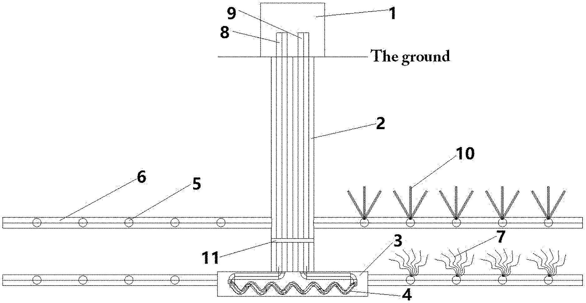
[0007] A geothermal development system comprises a ground lifting system 1, a large-diameter vertical shaft 2, an underground high temperature and high pressure heat transfer pool 3, a heat transfer diversion channel 4, a hot mine blasting fracture reservoir 7 formed by an approach blasting roadway 5 and a main roadway 6. The hot ore development system is provided with an injection pipe 8 and a collection pipe 9 along the inner wall of a large-diameter vertical shaft 2. The injection pipe 8 is connected with the collection pipe 9 through the heat transfer diversion channel 4 in the borehole of the underground high temperature and high pressure heat transfer pool 3 in the dry hot rock. The main roadway 6 for circulation is arranged around the underground high temperature and high pressure heat transfer pool 3. Multi-layer of the main roadway 6 is arranged longitudinally along the large-diameter vertical shaft 2 and underground high temperature and the high pressure heat transfer pool 3 as required. The approach blasting roadways 5 are arranged horizontally in multiple drainage channels along the main roadway 6, and rock is loosened and blasted by caving method to form a hot mine blasting fracture reservoir 7. In addition, a movable sealing device 11 is arranged above the large-diameter vertical shaft 2 corresponding to the hot mine blasting fracture reservoir 7. Then, water is injected into the underground high temperature and high pressure heat transfer pool 3 to store water and form hydrothermal rock through the injection pipe 8, and the water injection function will not be recovered and closed. Using the U-tube principle, the cold water and the hydrothermal rock in the underground high temperature and high pressure heat transfer pool 3 are exchanged for heat by the injection pipe 8 and the collection pipe 9, realizing the double heat transfer. It not only obtains the heat in the dry hot rock, but also absorbs the heat of water heat exchange, forming a closed heat exchange system. Necessary personnel, equipment and mine resources are transported by the ground lifting system 1. The injection pipe 8 and the collecting pipe 9 are connected to power generation working platform installed on surface power generation system to form a closed cycle.
[0008] The section of the heat transfer diversion channel 4 is arranged into a circular pipe or roadway. The multi-layer is arranged in a spiral shape, which is arranged into multiple layers according to the site situation or actual requirements. The movable seal device 11 achieves the seal of the large-diameter vertical shaft 2.
[0009] The diameter of the large-diameter vertical shaft 2 shall be large enough for the injection pipe 8 and the collection pipe 9 to be installed in the inner wall of the large-diameter vertical shaft 2 according to the on-site requirements.
[0010] The heat transfer diversion channel 4 is made of materials with good corrosion resistance and thermal conductivity. The injection pipe 8 and the collection pipe 9 are made of materials resistant to high temperature, high pressure and heat insulation.
[0011] The movable sealing device 11 is arranged on the interior of a large-diameter vertical shaft 2. A support system 13 provided on the outer wall of the panel structure 12 of the movable sealing device 11 is matched with the peripheral fixed system 15 provided on the inner wall of the large-diameter vertical shaft 2 to realize adjustment slip and fixing of the positioning card. The movable sealing device 11 is adjusted according to the hot mine blasting fracture reservoir 7 and is located above the hot mine blasting fracture reservoir 7. The movable sealing device 11 mainly consists of the panel structure 12, the support system 13, a hydraulic device 14 and the peripheral fixed system 15. The panel structure 12 is the main structure, which has a certain thickness, and the internal arrangement of hydraulic devices. The support system 13 is arranged on the outer wall of the panel structure 12 and is matched with the peripheral fixed system 15 provided on the inner wall of the large-diameter vertical shaft 2, such as a buckle, etc. The hydraulic device 14 is positioned around the borehole of the panel structure 12 through the injection pipe 8 and the collection pipe 9 to hold the injection pipe 8 and the collection pipe 9 in place and is controlled by the mechanism. The peripheral fixed system 15 is supported on the inner wall of the large diameter vertical shaft 2, which is arranged in a continuous vertical way along the inner wall of the large-diameter vertical shaft 2 to fix the movable support system 13.
[0012] The movable sealing device 11 is arranged in two or more floors to prevent excessive loss at high temperature in the lower part of the shaft.
[0013] The panel structure 12 may be made of steel or concrete.
[0014] A construction method of geothermal development system comprises the following steps:
[0015] S1. construct a large-diameter vertical shaft 2 by means of shaft construction technology. After reaching the target layer, use the roadway construction technology to develop the underground high temperature and high pressure heat transfer pool 3 and the main roadway 6 laterally along the target layer. Multi-layer of the main roadway 6 is arranged longitudinally along large-diameter vertical shaft 2 as required.
[0016] S2. multi-row approach blasting roadway 5 is formed along the horizontal direction of the main roadway 6. In addition, blasting pipes 10 are arranged in advance in the approach blasting roadway 5. The orderly blasting of caving method is used to loosen the rock layer of hot ore and form the hot mine blasting fracture reservoir 7. Necessary personnel, equipment and mine resources are transported by the ground lifting system 1;
[0017] S3. a movable sealing device 11 shall be installed above the large-diameter vertical shaft 2 corresponding to the hot mine blasting fracture reservoir 7. The movable sealing device 11 is moved up and down along the large-diameter vertical shaft 2 to reduce heat loss according to the actual engineering requirements;
[0018] S4. lay an injection pipe 8 and a collection pipe 9 along the inner wall of a large-diameter vertical shaft 2 and extend it to an underground high temperature and high pressure heat transfer pool 3 to form a multi-layer spiral heat transfer diversion channel 4. Water is injected into the underground high temperature and high pressure heat transfer pool 3 by the injection pipe 8. After reaching a certain amount, water is closed to form hydrothermal rock. The injection pipe 8 and the collection pipe 9 exchange heat energy between cold water and the hydrothermal rock in the underground high temperature and high pressure heat transfer pool 3 to realize double heat transfer and form a closed cycle connected with the power generation working platform on the ground power generation system.
[0019] In Step S2, blasting is carried out in the approach blasting roadway 5. The loose subsidence area is formed by caving method, which is connected with the main roadway 6 and the underground high temperature and high pressure heat transfer pool 3 to form a penetrating area. When multi-layer of main roadway 6 is arranged, an approach blasting roadway 5 is arranged for each layer of main roadway 6.
[0020] In Step S3, the peripheral fixed system 15 is firstly set up during the construction of the large-diameter vertical shaft 2. The panel structure 12, the support system 13 and the hydraulic device 14 are assembled and integrated into the whole system in advance. Then, after the completion of construction of the large-diameter vertical shaft 2, the movable seal device 11 is placed in the large-diameter vertical shaft 2 and fixed in place in the peripheral fixation system 15 with the support system 13 on the inner wall of the large-diameter vertical shaft 2. Then the construction of the injection pipe 8 and the collection pipe 9 are carried out. Insert the injection pipe 8 and the collection pipe 9 through the removable seal 11 device and secure the injection pipe 8 and the collecting pipe 9 with a hydraulic device 14. Finally, according to the needs of the project, the movable sealing device 11 is moved up and down to select the appropriate position for fixed treatment;
[0021] In Step S4, underground high temperature and high pressure heat transfer pool 3 is not recycled after water is injected, forming hydrothermal rock, and heat transfer diversion channel 4 is used for heat exchange.
Beneficial Effects of the Present Invention
[0022] 1) the construction of a new deep shaft or the continuous construction of a shaft on the original shaft of the mine are implemented in the geothermal development system provided by the invention. Carry out the horizontal roadway excavation after excavation to the target formation, so as to improve the liquid flow rate and the contact area between liquid and heat source. Conduct the rupture of hot dry rock to improve its permeability and fluid property through drilling, blasting and other measures. Or a heat conduction pipe is laid in the hot dry rock, and the liquid medium carrying heat energy is collected by the collection pipe, which is transported to the power generation platform through the wellbore for power generation.
[0023] 2) Compared with traditional Enhanced Geothermal Systems (EGS) using two small hole and the medium of the liquid in the target hot dry rock transverse flow absorption of heat, the invention adopts a collection of large-diameter vertical shaft for geothermal energy. It can make medium of the liquid in the target hot dry rock longitudinal flow and transverse flow, and the extraction of geothermal energy method reduces the number of drilling platform and ground occupying space.
[0024] 3) The traditional enhanced geothermal system (EGS) mainly relies on the method of hydraulic fracturing to increase the porosity and permeability of the target hot and dry rock, but it cannot guarantee the porosity and permeability of hot and dry rock, and pipelines are easy to be blocked during operation. The invention can effectively avoid the above shortcomings, and at the same time can give full play to the artificial measures to ensure the porosity and permeability of dry hot rock and increase the heat exchange area. At the same time, the thermal conduction pipe can be used to fully absorb the heat of dry hot rock and avoid the pipe clog.
[0025] 4) The invention is conducive to the construction of deep mining heat system.
[0026] 5) The invention does not use hydraulic fracturing technology, does not cause earthquakes, and does not have to worry about water pollution.
[0027] 6) The invention can greatly increase the area of water and heat exchange and realize large-capacity geothermal development.
[0028] 7) The invention makes use of the U-tube principle, and the upper and lower cold-water closed circulation scheme can minimize the system energy consumption, and at the same time completely avoid the corrosive pipeline or environmental pollution caused by harmful minerals in the deep.
[0029] 8) The invention can be combined with deep mineral resources exploitation to achieve a win-win situation between mineral resources and geothermal resources utilization.
[0030] 9) The movable sealing device has strong mobility and is easy to install. Besides, the structure of the shaft construction device is strong, which can well transfer the pressure around the shaft and effectively control the extrusion volume around the shaft to meet the design requirements.
[0031] 10) The mobile construction operation of mobile devices can be recycled and placed as the mining depth of hot ore increases, which will reduce the waste of materials.
DESCRIPTION OF THE DRAWINGS
[0032] FIG. 1 is a structural diagram of the geothermal development system in the invention.
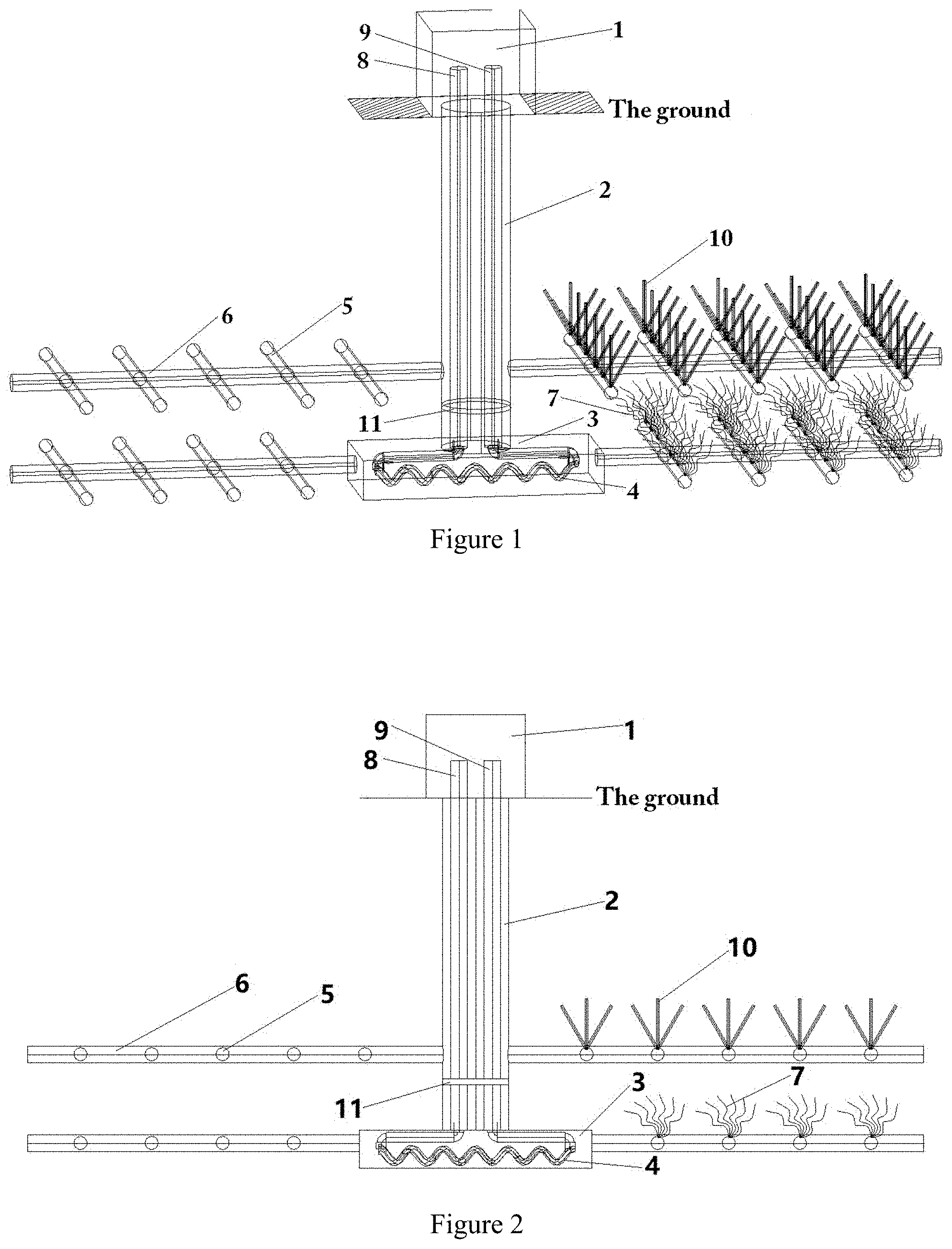
[0033] FIG. 2 is a schematic diagram of installation of the heat conduction tube in the invention.
[0034] FIG. 3 is a overlooking structure diagram of the geothermal development system in the invention.
[0035] FIG. 4 is a structure diagram of the movable shaft sealing device in the invention.
[0036] Where, 1 ground lifting system; 2 large-diameter vertical shaft; 3 underground high temperature and high pressure heat transfer pool; 4 heat transfer diversion channel; 5 approach blasting roadway; 6 main roadway; 7 hot mine blasting fracture reservoir; 8 injection pipe; 9 collection pipe; 10 blasting pipe; 11 movable sealing device; 12 panel structure; 13 support system; 14 hydraulic device; 15 peripheral fixed system; 16 lining.
DETAILED DESCRIPTION
[0037] The specific embodiments of the present invention will be further described below in conjunction with the drawings and technical solutions.
Example 1
[0038] A geothermal development system is provided in this embodiment as shown in FIG. 1, including a large-diameter vertical shaft 2. The diameter of large-diameter vertical shaft 2 is 3-10 m, and its vertical depth is 3000-10000 m, until the underground development forms the underground high temperature and high pressure heat transfer pool 3. The diameter of underground high temperature and high pressure heat transfer pool 3 is 30-50 m and the height is about 1 m, which is related to the number of layers set in heat exchanger diversion channel 4. Both the injection pipe 8 and the collection pipe 9 are arranged along the inner wall of the large-diameter vertical shaft 2, and the heat transfer diversion channel 4 is formed in the underground high temperature and high pressure heat transfer pool 3. The injection pipe 8 and the collection pipe 9 are made of materials resistant to high temperature, high pressure and heat insulation.
[0039] The injection pipe 8 is connected with the collection pipe 9 through the heat transfer diversion channel 4 in the underground high temperature and high pressure heat transfer pool 3. The diameter of heat transfer diversion channel 4 is 10-300 mm. The injection pipe 8 and the collection pipe 9 are connected to the power generation working platform to form a closed cycle.
[0040] At the same time, the circulation main roadway 6 is arranged around the underground high temperature and high pressure heat transfer pool 3, and the multi-layer of main roadway 6 can be arranged longitudinally along the large-diameter vertical shaft 2 according to the needs. Main roadway 6 has a diameter of 0.5 m and a length of 250 m. In addition, multiple of approach blasting roadway 5 was set along the level of main roadway 6. Approach blasting roadway 5 was used for orderly blasting to loosen the hot ore rock layer and formed hot mine blasting fracture reservoir 7 with main roadway 6. Transportation of necessary personnel, equipment and mine resources shall be carried out by ground lifting system 1.
[0041] The working process of the geothermal development system is as follows: the medium liquid, such as water, is injected from the power generation working platform to the injection pipe 8. Under the action of pressure, the liquid reaches the injection port through the injection pipe 8, enters the target formation from the injection port, and enters the injection roadway. The liquid is filled up and injected into the tunnel. The liquid then passes through a hole in the hot dry rock under pressure. The liquid absorbs geothermal energy through a hole in the hot dry rock and reaches a collection tunnel or heat conducting pipe. The liquid fills the collection roadway, enters the collection pipe 9 through the collection port, and carries the liquid or vapor containing geothermal energy to the power generation working platform for power generation. In this way, geothermal energy from the target formation is continuously brought to the surface for power generation.
[0042] To increase the liquid contact surface, the heat transfer diversion channel 4 is made of materials with high strength, corrosion resistance and good thermal conductivity. As shown in FIG. 2, multiple layers can be arranged in heat transfer diversion channel 4, and a movable sealing device 11 can be set above the hot mine blasting fracture reservoir 7. One end of heat transfer diversion channel 4 is connected with the injection pipe 8 and the other end is connected with the collection pipe 9. Thus, heat transfer diversion channel 4 can not only obtain the heat in the dry hot rock, but also absorb the heat exchange of water and heat, and bring the heat out through the liquid media in the collection pipe 9.
[0043] The present embodiment also provides a construction method for the geothermal development system, comprising the following steps:
[0044] S1. construct a large-diameter vertical shaft 2 by means of shaft construction technology. After reaching the target layer, use the roadway construction technology to develop the underground high-temperature and high-pressure heat transfer pool 3 and main roadway 6 laterally along the target layer. Multi-layer of the main roadway 6 is arranged longitudinally along large-diameter vertical shaft 2 as required.
[0045] S2. a multi-row of approach blasting roadway 5 is formed along the horizontal direction of the main roadway 6. In addition, blasting pipes 10 are arranged in advance in the approach blasting roadway 5. The orderly blasting of caving method is used to loosen the rock layer of hot ore and form the hot mine blasting fracture reservoir 7. Necessary personnel, equipment and mine resources are transported by the ground lifting system 1;
[0046] S3. a movable sealing device 11 shall be installed above the large-diameter vertical shaft 2 corresponding to the hot mine blasting fracture reservoir 7. The movable sealing device 11 is moved up and down along the large-diameter vertical shaft 2 to reduce heat loss according to the actual engineering requirements;
[0047] S4. lay an injection pipe 8 and a collection pipe 9 along the inner wall of a large-diameter vertical shaft 2 and extend it to an underground high temperature and high pressure heat transfer pool 3 to form a multi-layer spiral heat transfer diversion channel 4. Water is injected into the underground high temperature and high pressure heat transfer pool 3 by the injection pipe 8. After reaching a certain amount, water is closed to form hydrothermal rock. The injection pipe 8 and the collection pipe 9 exchange heat energy between cold water and the hydrothermal rock in the underground high-temperature and high-pressure heat transfer pool 3 to realize double heat transfer and form a closed cycle connected with the power generation working platform on the ground power generation system.
[0048] In Step S2, in the approach blasting roadway 5, blasting is carried out. The loose subsidence area is formed by caving method, which is connected with the main roadway 6 and the underground high temperature and high pressure heat transfer pool 3 to form a penetrating area. When multi-layer of main roadway 6 is arranged, an approach blasting roadway 5 is arranged for each layer of main roadway 6.
[0049] In Step S3, the surrounding fixed system 15 is firstly set up during the construction of the large-diameter vertical shaft 2. The panel structure 12, the support system 13 and the hydraulic device 14 are assembled and integrated into the whole system in advance. Then, after the completion of construction of the large-diameter vertical shaft 2, the movable seal device 11 is placed in the large-diameter vertical shaft 2 and fixed in place in the peripheral fixation system 15 with the support system 13 on the inner wall of the large-diameter vertical shaft 2. Then the construction of the injection pipe 8 and the collection pipe 9 are carried out. Insert the injection pipe 8 and the collection pipe 9 through the removable seal 11 and secure the injection pipe 8 and the collection pipe 9 with a hydraulic device 14. Finally, according to the needs of the project, the movable sealing device 11 is moved up and down to select the appropriate position for fixed treatment;
[0050] In Step S4, the underground high temperature and high pressure heat transfer pool 3 is not recycled after water is injected, forming hydrothermal rock, and heat transfer diversion channel 4 is used for heat exchange.
[0051] Arrange injection pipe 8 and collection pipe 9, connect the ground and target layer, and form a complete loop in the geothermal development system and its construction method in this embodiment, by utilizing the large-diameter vertical shaft 2 and roadway formed by mine excavation technology and its advantages of large underground space and wide liquid contact surface. Combined with the technology of drilling and blasting rock breaking, the target layer is fractured. Finally, the liquid media is made to obtain the heat of the dry hot rock through the heat transfer diversion channel 4 to the heat exchange pool filled with water, and then the liquid or steam containing geothermal energy is carried to the ground for generating electricity through the collection pipe 9.
Example 2
[0052] A geothermal development system is provided in this embodiment as shown in FIG. 2, including a large-diameter vertical shaft 2. The diameter of large-diameter vertical shaft 2 is 3-10 m, and its vertical depth is 3000-10000 m, until the underground development forms the underground high temperature and high pressure heat transfer pool 3. The diameter of the underground high temperature and high pressure heat transfer pool 3 is 30-50 m and the height is about 1 m, which is related to the number of layers set in heat exchanger diversion channel 4. Both the injection pipe 8 and the collection pipe 9 are arranged along the inner wall of the large-diameter vertical shaft 2, and the heat transfer diversion channel 4 is formed in the underground high temperature and high pressure heat transfer pool 3. The injection pipe 8 and the collection pipe 9 are made of materials resistant to high temperature, high pressure and heat insulation.
[0053] Boreholes are set in the dry hot rocks, and underground high temperature and high pressure heat transfer pool 3 is paved with heat transfer channel 4, which is made of materials with high strength, corrosion resistance and good thermal conductivity. As shown in FIG. 2, a number of heat transfer channel 4 is arranged in an annular way in the middle of the dry hot rock. Multiple layers can be arranged for the heat conduction pipe, and a movable sealing device 11 is set above the blasting layer. One end of heat transfer diversion channel 4 is connected with injection pipe 8, and the other end is connected with the collection pipe 9. Both injection pipe 8 and collection pipe 9 are connected with the power generation working platform, thus forming a closed cycle. The ground lifting system 1 shall carry out necessary transportation of personnel, equipment and mine resources, so that the heat conduction tube can fully absorb the heat from the dry hot rock, and carry the heat energy to the power generation working platform through collecting the liquid media in the collection pipe 9.
[0054] The geothermal development system works by injecting a medium liquid, such as water, from the power generation platform into the injection pipeline. The liquid reaches the heat conducting pipe through the injection pipe under pressure. The liquid still absorbs geothermal energy under the action of pressure through the heat conduction pipe in the dry hot rock and the water in the underground high temperature and high pressure heat transfer pool, and reaches the collection pipe, through which the liquid or steam carrying geothermal energy is transported to the power generation platform on the ground to generate electricity. In this way, the ground heat of the destination layer is constantly brought to the ground for electricity generation.
[0055] Ordinary technicians in the field will be aware that the embodiments described here are intended to help readers understand the principles of the invention and the scope of protection of the invention is not limited to such special statements and embodiments. According to these technical inspirations disclosed by the invention, ordinary technicians in this field may make various other specific deformation and combinations which are not divorced from the essence of the invention, and such deformation and combinations are still within the scope of protection of the invention.
* * * * *
D00000
D00001
D00002
XML
uspto.report is an independent third-party trademark research tool that is not affiliated, endorsed, or sponsored by the United States Patent and Trademark Office (USPTO) or any other governmental organization. The information provided by uspto.report is based on publicly available data at the time of writing and is intended for informational purposes only.
While we strive to provide accurate and up-to-date information, we do not guarantee the accuracy, completeness, reliability, or suitability of the information displayed on this site. The use of this site is at your own risk. Any reliance you place on such information is therefore strictly at your own risk.
All official trademark data, including owner information, should be verified by visiting the official USPTO website at www.uspto.gov. This site is not intended to replace professional legal advice and should not be used as a substitute for consulting with a legal professional who is knowledgeable about trademark law.