Pulsation-free Wet Spraying Machine
CHEN; Lianjun ; et al.
U.S. patent application number 16/964511 was filed with the patent office on 2021-01-14 for pulsation-free wet spraying machine. The applicant listed for this patent is SHANDONG UNIVERSITY OF SCIENCE AND TECHNOLOGY. Invention is credited to Wenhui BIAN, Lianjun CHEN, Guoming LIU, Zhaoxia LIU, Guanguo MA, Wen NIE, Gang PAN, Gang WANG.
| Application Number | 20210010372 16/964511 |
| Document ID | / |
| Family ID | 1000005136882 |
| Filed Date | 2021-01-14 |

| United States Patent Application | 20210010372 |
| Kind Code | A1 |
| CHEN; Lianjun ; et al. | January 14, 2021 |
PULSATION-FREE WET SPRAYING MACHINE
Abstract
A pulsation-free wet spraying machine resolves the issue of pulsing during pumping of a concrete spraying machine. The wet spraying machine includes a frame, a pumping mechanism, a swing mechanism and a hydraulic system, wherein the pumping mechanism includes a hopper, a material chamber, a concrete feeding mechanism, an auxiliary feeding mechanism and a distribution valve, the hopper is disposed above the material chamber, the concrete feeding mechanism and the auxiliary feeding mechanism each include a hydraulic cylinder, a concrete piston and a concrete cylinder, the concrete cylinder of the concrete feeding mechanism and an auxiliary concrete cylinder of the auxiliary feeding mechanism are both connected with the material chamber, a discharge port is disposed on the material chamber, sealing between the distribution valve and the discharge port is provided by a sealing ring, the distribution valve is disposed inside the material chamber, a front friction plate and a rear friction plate are further disposed inside the material chamber, the swing mechanism includes a swing hydraulic cylinder, a mandrel, a swing arm and a swing hydraulic cylinder base, and the mandrel drives the distribution valve to swing. In addition, The pulsation-free wet spraying machine stably feeds a material, has a compact structure, and is wear-resistant.
| Inventors: | CHEN; Lianjun; (Qingdao City, CN) ; MA; Guanguo; (Qingdao City, CN) ; LIU; Guoming; (Qingdao City, CN) ; PAN; Gang; (Qingdao City, CN) ; LIU; Zhaoxia; (Qingdao City, CN) ; WANG; Gang; (Qingdao City, CN) ; NIE; Wen; (Qingdao City, CN) ; BIAN; Wenhui; (Qingdao City, CN) | ||||||||||
| Applicant: |
|
||||||||||
|---|---|---|---|---|---|---|---|---|---|---|---|
| Family ID: | 1000005136882 | ||||||||||
| Appl. No.: | 16/964511 | ||||||||||
| Filed: | December 10, 2018 | ||||||||||
| PCT Filed: | December 10, 2018 | ||||||||||
| PCT NO: | PCT/CN2018/120096 | ||||||||||
| 371 Date: | July 23, 2020 |
| Current U.S. Class: | 1/1 |
| Current CPC Class: | F04B 15/02 20130101; F04B 7/0258 20130101; F04B 53/10 20130101; F04B 15/023 20130101; E21D 11/105 20130101; F04B 7/04 20130101; F04B 7/0034 20130101 |
| International Class: | E21D 11/10 20060101 E21D011/10; F04B 15/02 20060101 F04B015/02; F04B 7/04 20060101 F04B007/04; F04B 53/10 20060101 F04B053/10 |
Foreign Application Data
| Date | Code | Application Number |
|---|---|---|
| Jul 24, 2018 | CN | 201810815021.7 |
Claims
1. A pulsation-free wet spraying machine, comprising a frame, a pumping mechanism, a swing mechanism and a hydraulic system, wherein the pumping mechanism comprises a hopper, a material chamber, a concrete feeding mechanism, an auxiliary feeding mechanism, a distribution valve and a discharge port, the hopper is disposed above the material chamber, two concrete cylinders of the concrete feeding mechanism are in communication with the material chamber, and an auxiliary concrete cylinder of the auxiliary feeding mechanism is in communication with the distribution valve in the material chamber; the distribution valve is disposed inside the material chamber, a front end of the distribution valve is in communication with the discharge port, and a rear end of the distribution valve is in communication with the concrete cylinders and the auxiliary concrete cylinder in a swinging process; the swing mechanism comprises a swing hydraulic cylinder, a mandrel, a swing arm and a swing hydraulic cylinder base, the swing hydraulic cylinder base is mounted at an outer side of the material chamber, the swing hydraulic cylinders are symmetrically arranged at both sides of the swing hydraulic cylinder base, and the swing arm is hinged with the swing hydraulic cylinders; the swing arm is mounted through a spline in cooperation with the mandrel; the motor/hydraulic system comprises a hydraulic oil tank and a motor, and the pumping mechanism, the swing mechanism and the motor/hydraulic system are all disposed on the frame; in a swinging process of the distribution valve, the rear end of the distribution valve is always in communication with the auxiliary concrete cylinder, and the front end of the distribution valve is always in communication with the discharge port; the concrete cylinder of the concrete feeding mechanism sucks a material from the material chamber, the concrete feeding mechanism pushes the material in the concrete cylinder to the distribution valve through the concrete piston, so that the material reaches the discharge port through the distribution valve; when any of the concrete cylinders pumps the material, the auxiliary concrete piston in the auxiliary concrete cylinder retracts to enable the auxiliary concrete cylinder to suck the material from the distribution valve; when the distribution valve swings, the material in the auxiliary concrete cylinder is pushed to the distribution valve; when the auxiliary concrete piston in the auxiliary concrete cylinder pushes the material, baffle plates at both wings of the distribution valve friction plate block outlets of the concrete cylinders.
2. The pulsation-free wet spraying machine according to claim 1, wherein the concrete feeding mechanism comprises main hydraulic cylinder, a concrete piston and a concrete cylinder, and a piston rod of the main hydraulic cylinder pushes the concrete piston to move inside the concrete cylinder; the auxiliary feeding mechanism comprises an auxiliary hydraulic cylinder, an auxiliary concrete piston and an auxiliary concrete cylinder, and an auxiliary piston rod of the auxiliary hydraulic cylinder pushes the auxiliary concrete piston to move inside the auxiliary concrete cylinder.
3. The pulsation-free wet spraying machine according to claim 2, wherein the hopper is mounted above the material chamber, the concrete feeding mechanism and the auxiliary feeding mechanism are arranged at a side surface of the material chamber, the main hydraulic cylinder is mounted on a water rinsing bath, and the auxiliary hydraulic cylinder is mounted above the main hydraulic cylinders.
4. The pulsation-free wet spraying machine according to claim 1, wherein a distribution valve, a rear friction plate, a distribution valve friction plate, a rubber spring, a sealing ring and a front friction plate are disposed inside the material chamber, the rear friction plate and the distribution valve friction plate are sequentially disposed between the concrete cylinder of the concrete feeding mechanism and the distribution valve, the rubber spring is disposed between the distribution valve friction plate and the distribution valve, baffle plates are disposed at both wings of the distribution valve friction plate, and the sealing ring is disposed between the distribution valve and the front friction plate; the distribution valve friction plate and the rear friction plate are in close contact.
5. The pulsation-free wet spraying machine according to claim 1, wherein an opening of the front end of the distribution valve is in a shape same as a shape of the discharge port swept by swing of the distribution valve, a shape of an upper part of an opening of the rear end of the distribution valve is same as a shape of the auxiliary concrete cylinder swept by the swing of the distribution valve, and a shape of a lower part of the opening of the rear end of the distribution valve is same as a shape of the concrete cylinder swept by the swing of the distribution valve.
6. (canceled)
7. The pulsation-free wet spraying machine according to claim 1, wherein the front friction plate is disposed between the distribution valve and the discharge port, and the distribution valve friction plate and the rear friction plate are disposed between the distribution valve and the concrete cylinder of the concrete feeding mechanism; one through-hole is disposed on the front friction plate, and three through-holes are disposed on the rear friction plate; the distribution valve friction plate and the rear friction plate are in close contact.
8. (canceled)
9. (canceled)
Description
TECHNICAL FIELD
[0001] The present disclosure relates to the technical field of engineering equipment, and in particular to a pulsation-free wet spraying machine.
BACKGROUND
[0002] Concrete wet spraying machines are widely applied to locations such as coal mine roadways and road tunnels requiring concrete spraying supporting. The common concrete wet spraying machine is a plunger-type concrete wet spraying machine that works as follows: pumping is realized by switching a distribution valve. In a pumping process, a pulsation phenomenon may be caused due to swing of the distribution valve, thereby increasing a pipe blocking probability in the pumping process and leading to a rebound problem in a concrete spraying process.
SUMMARY
[0003] To solve the pulsation problem and the sprayed concrete rebound problem of the concrete wet spraying machine in a working process, the present disclosure provides a pulsation-free wet spraying machine. A specific technical solution is described below.
[0004] The pulsation-free wet spraying machine includes a frame, a pumping mechanism, a swing mechanism and a hydraulic system, where the pumping mechanism includes a hopper, a material chamber, a concrete feeding mechanism, an auxiliary feeding mechanism, a distribution valve and a discharge port, the hopper is disposed above the material chamber, two concrete cylinders of the concrete feeding mechanism communicate with the material chamber, and an auxiliary concrete cylinder of the auxiliary feeding mechanism communicates with the distribution valve in the material chamber; the distribution valve is disposed inside the material chamber, a front end of the distribution valve communicates with the discharge port, and a rear end of the distribution valve communicates with the concrete cylinder and the auxiliary concrete cylinder in a swinging process; the swing mechanism includes a swing hydraulic cylinder, a mandrel, a swing arm and a swing hydraulic cylinder base, the swing hydraulic cylinder base is mounted at an outer side of the material chamber, the swing hydraulic cylinders are symmetrically arranged at both sides of the swing hydraulic cylinder base, and the swing arm is hinged with the swing hydraulic cylinder; the swing arm is mounted through a spline in cooperation with the mandrel; the hydraulic system includes a hydraulic oil tank and a motor, and the pumping mechanism, the swing mechanism and the hydraulic system are all disposed on the frame.
[0005] Preferably, the concrete feeding mechanism includes a main hydraulic cylinder, a concrete piston and a concrete cylinder, and a piston rod of the main hydraulic cylinder pushes the concrete piston to move inside the concrete cylinder; the auxiliary feeding mechanism includes an auxiliary hydraulic cylinder, an auxiliary concrete piston and an auxiliary concrete cylinder, and an auxiliary piston rod of the auxiliary hydraulic cylinder pushes the auxiliary concrete piston to move inside the auxiliary concrete cylinder.
[0006] Preferably, the hopper is mounted above the material chamber, the concrete feeding mechanism and the auxiliary feeding mechanism are arranged at a side surface of the material chamber, the main hydraulic cylinder is mounted on a water rinsing bath, and the auxiliary hydraulic cylinder is mounted above the main hydraulic cylinders.
[0007] Preferably, a distribution valve, a rear friction plate, a distribution valve friction plate, a rubber spring, a sealing ring and a front friction plate are disposed inside the material chamber, the rubber spring is disposed between the distribution valve friction plate and the distribution valve, baffle plates are disposed at both wings of the distribution valve friction plate, and the sealing ring is disposed between the distribution valve and the front friction plate.
[0008] Preferably, an opening of the front end of the distribution valve is in a shape same as the discharge port swept by swing of the distribution valve, a shape of an upper part of an opening of the rear end of the distribution valve is same as a shape of the auxiliary concrete cylinder swept by the swing of the distribution valve, and a shape of a lower part of the opening of the rear end of the distribution valve is same as a shape of the concrete cylinder swept by the swing of the distribution valve.
[0009] Preferably, in the swinging process of the distribution valve, the rear end of the distribution valve always is in communication with the auxiliary concrete cylinder, and the front end of the distribution valve always is in communication with the discharge port.
[0010] Preferably, the front friction plate is disposed between the distribution valve and the discharge port, and the distribution valve friction plate and the rear friction plate are disposed between the distribution valve and the concrete cylinder of the concrete feeding mechanism; one through-hole is disposed on the front friction plate, and three through-holes are disposed on the rear friction plate; the distribution valve friction plate and the rear friction plate are in close contact.
[0011] Preferably, the concrete cylinder of the concrete feeding mechanism sucks a material from the material chamber, the concrete feeding mechanism pushes the material in the concrete cylinder to the distribution valve through the concrete piston, so that the material reaches the discharge port through the distribution valve; when any of the concrete feeding mechanisms pumps the material, the auxiliary concrete piston in the auxiliary feeding mechanism retracts to enable the auxiliary concrete cylinder to suck the material from the distribution valve; when the distribution valve swings, the material in the auxiliary concrete cylinder is pushed to the distribution valve.
[0012] Preferably, when the auxiliary concrete piston in the auxiliary concrete cylinder pushes the material, baffle plates at both wings of the distribution valve friction plate block outlets of the concrete cylinders.
[0013] Beneficial effects of the present disclosure can be realized as follows: (1) the auxiliary feeding mechanism and the concrete feeding mechanism jointly pump the material in the material chamber to the distribution valve; when the concrete piston pushes the material, the auxiliary concrete piston retracts to enable the auxiliary concrete cylinder to suck part of material; when the concrete cylinder is blocked by the distribution valve friction plate, the auxiliary concrete cylinder pumps the material, thereby solving the pumping pulsation problem caused by the swing of the distribution valve when two hydraulic cylinders pump the material; at the same time, parallel arrangement of the concrete feeding mechanism and the auxiliary feeding mechanism realizes a compact structure of the pumping mechanism, and pumping by the auxiliary feeding mechanism in the material chamber is more conducive to sealing; (2) friction plates are disposed at the front and rear ends of the distribution valve respectively, and the distribution valve friction plate and the front friction plate each are made of hard alloy, thereby strengthening sealing, preventing quick wear caused by the swing of the distribution valve, and prolonging the service life of equipment; the rubber spring is disposed between the distribution valve friction plate and the distribution valve to ensure close contact between the distribution valve friction plate and the rear friction plate, thereby strengthening sealing and improving stability of the distribution valve in the swinging process; (3) the swing arm is mounted through the spline in cooperation with the mandrel, and the mandrel is mounted through a mandrel cover in cooperation with a fitting slot at an upper part of the distribution valve to enable the mandrel to swing effectively along with the swing arm, thereby facilitating mounting.
BRIEF DESCRIPTION OF THE DRAWINGS
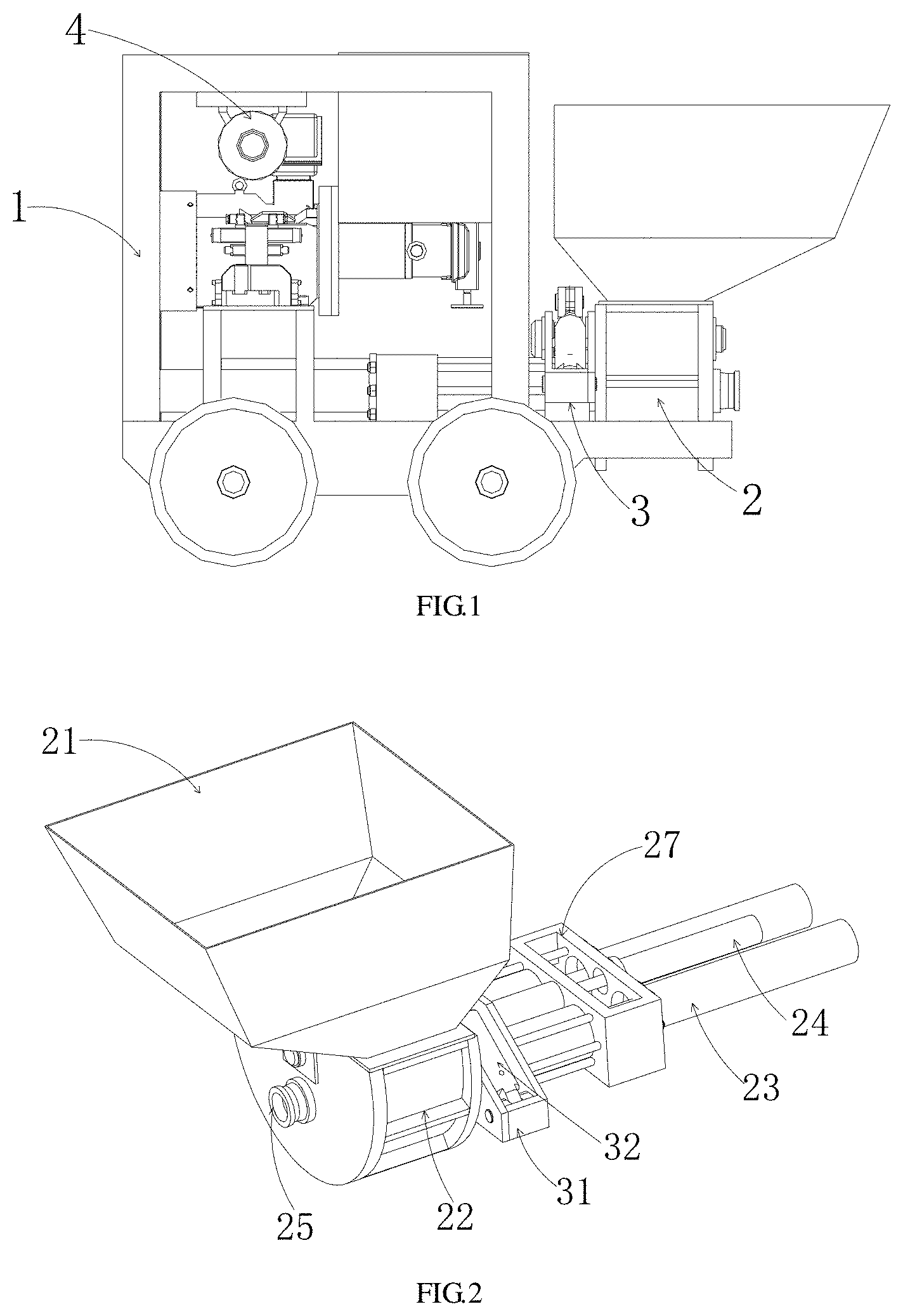
[0014] FIG. 1 is a schematic diagram illustrating an overall structure of a pulsation-free wet spraying machine according to an example of the present disclosure.
[0015] FIG. 2 is a schematic diagram illustrating mounting structures of a pumping mechanism and a swing mechanism according to an example of the present disclosure.
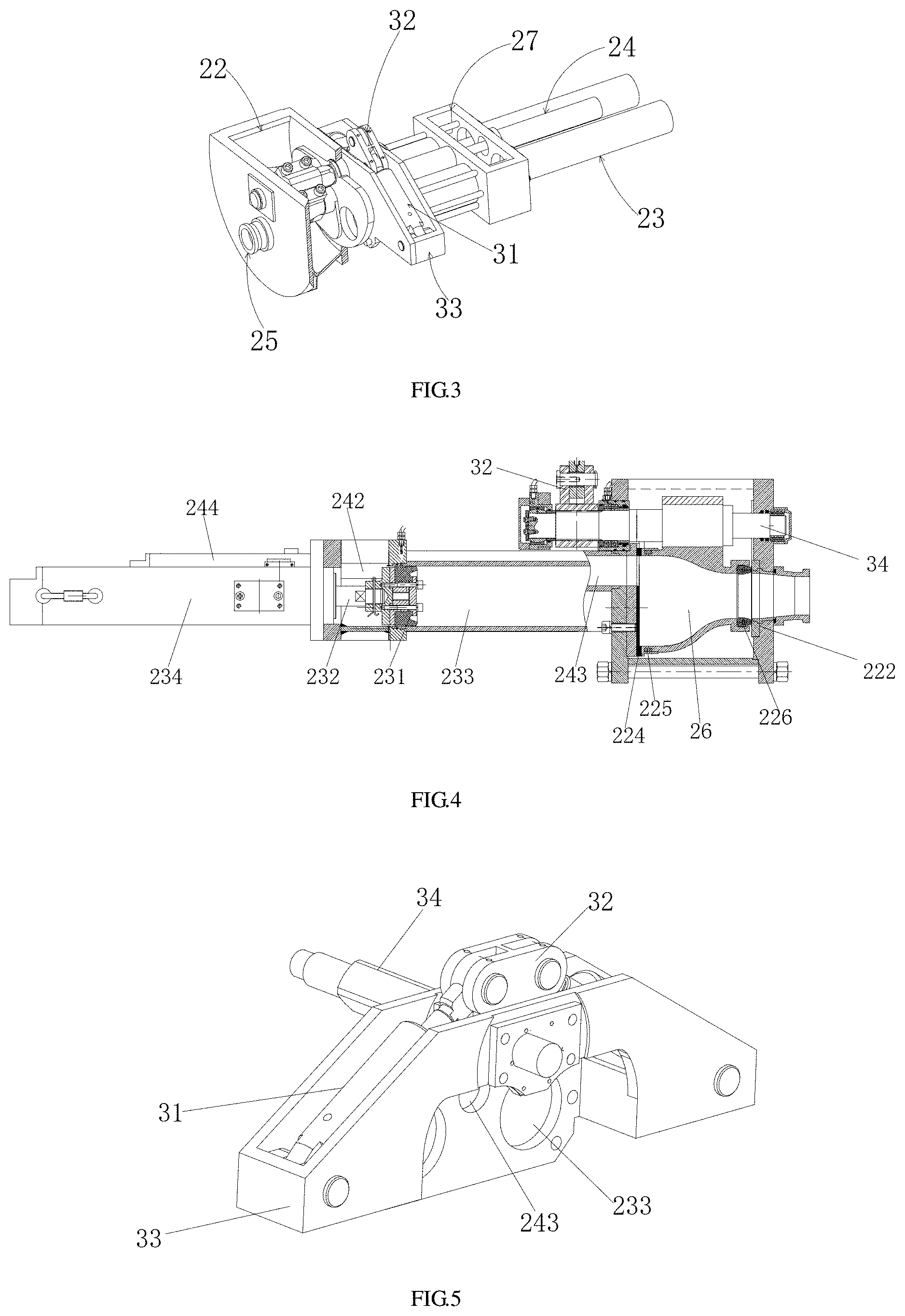
[0016] FIG. 3 is a schematic diagram illustrating partial structures of a pumping mechanism and a swing mechanism according to an example of the present disclosure.
[0017] FIG. 4 is a sectional schematic diagram illustrating structures of a pumping mechanism and a swing mechanism according to an example of the present disclosure.
[0018] FIG. 5 is a schematic diagram illustrating a swing mechanism according to an example of the present disclosure.
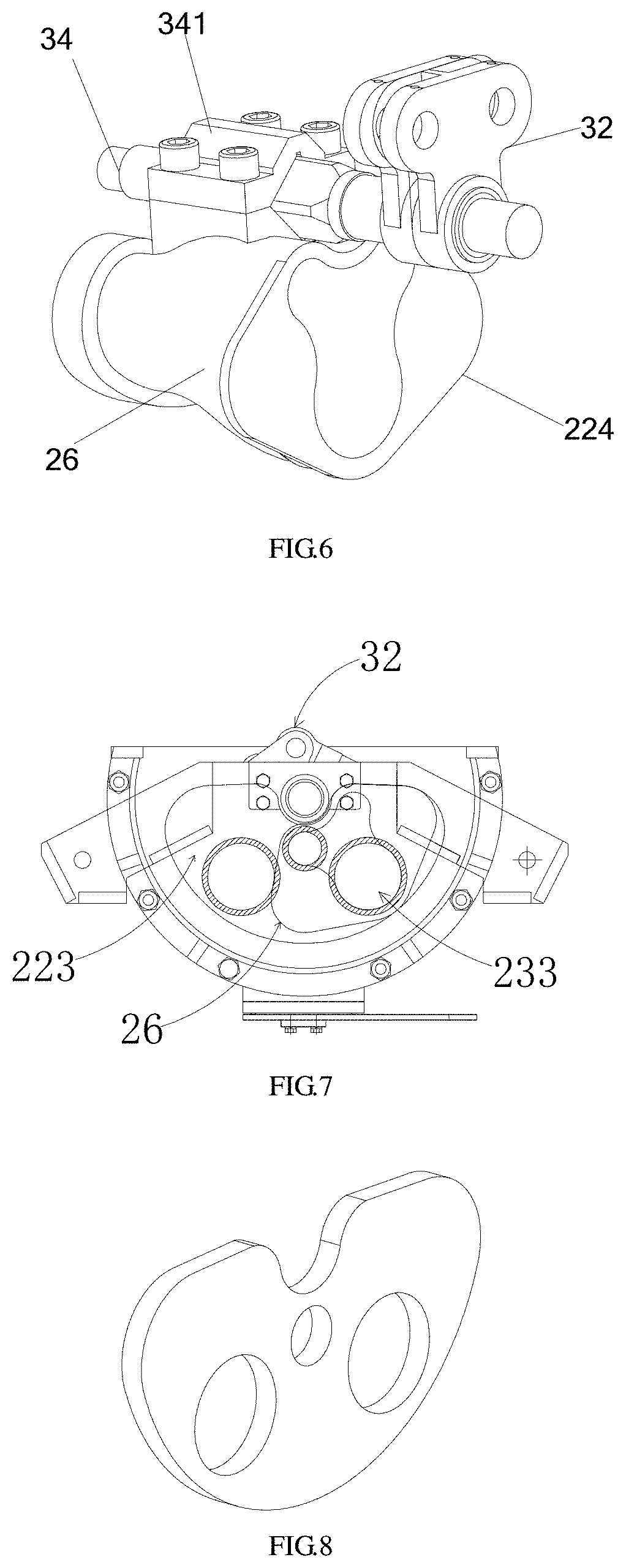
[0019] FIG. 6 is a mounting schematic diagram illustrating a distribution valve according to an example of the present disclosure.
[0020] FIG. 7 is a schematic diagram illustrating a swing structure of a distribution valve according to an example of the present disclosure.
[0021] FIG. 8 is a structural schematic diagram illustrating a rear friction plate of a distribution valve according to an example of the present disclosure.
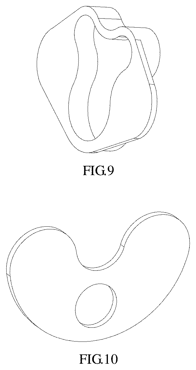
[0022] FIG. 9 is a structural schematic diagram illustrating a distribution valve friction plate according to an example of the present disclosure.
[0023] FIG. 10 is a structural schematic diagram illustrating a front friction plate of a distribution valve according to an example of the present disclosure.
[0024] Numerals of the drawings are described as follows: 1--frame, 2--pumping mechanism, 3--swing mechanism, 4--hydraulic system, 21--hopper, 22--material chamber, 222--front friction plate, 223--rear friction plate, 224--distribution valve friction plate, 225--rubber spring, 226--sealing ring, 23--concrete feeding mechanism, 231--concrete piston, 232--piston rod, 233--concrete cylinder, 234--main hydraulic cylinder, 24--auxiliary feeding mechanism, 241--auxiliary concrete piston, 242--auxiliary piston rod, 243--auxiliary concrete cylinder, 244--auxiliary hydraulic cylinder, 25--discharge port, 26--distribution valve, 27--water rinsing bath, 31--swing hydraulic cylinder, 32--swing arm, 33--swing hydraulic cylinder base, 34--mandrel, and 341--mandrel cover.
DETAILED DESCRIPTION OF THE EMBODIMENTS
[0025] As shown in FIGS. 1-10, a specific implementation of a pulsation-free wet spraying machine according to the present disclosure is described below.
[0026] Specifically, as shown in FIG. 1, the pulsation-free wet spraying machine includes a frame 1, a pumping mechanism 2, a swing mechanism 3 and a hydraulic system 4. Wheels are disposed on the frame 1 to facilitate movement of the wet spraying machine; the hydraulic system 4 includes a hydraulic oil tank and a motor, the hydraulic oil tank is disposed at an upper part of the frame 1, the motor and the hydraulic oil tank drive hydraulic cylinders of the swing mechanism 3 and the pumping mechanism 2 to move, and thus, the structure outputs stable power safely and reliably; the swing mechanism 3 and the pumping mechanism 2 are mounted cooperatively, a concrete feeding mechanism 23 of the pumping mechanism 2 is disposed at the bottom of the frame 1, and a hopper 21 of the pumping mechanism 2 is disposed at an upper front part of the frame. In this case, the pumping mechanism 2 realizes material pumping, and the swing mechanism 3 brings a distribution valve 26 to swing through swing of a mandrel 34.
[0027] As shown in FIGS. 2-4, the pumping mechanism 2 includes a hopper 21, a material chamber 22, a concrete feeding mechanism 23, an auxiliary feeding mechanism 24, a distribution valve 26, a discharge port 25 and a water rinsing bath 27. The hopper 21 is mounted above the material chamber 22, and a lower end of the hopper 21 is connected with the material chamber 22. The concrete feeding mechanism 23 includes two main hydraulic cylinders 234, two concrete pistons 231 and two concrete cylinders 233. The auxiliary feeding mechanism 24 includes an auxiliary hydraulic cylinder 244, an auxiliary concrete piston 241 and an auxiliary concrete cylinder 243. Two concrete cylinders 233 of the concrete feeding mechanism 23 are symmetrically arranged at a side surface of the material chamber 22, the concrete cylinders 233 of two concrete feeding mechanisms 23 communicate with the material chamber 22, and the auxiliary concrete cylinder 243 of the auxiliary feeding mechanism 24 communicates with the distribution valve 26. The distribution valve 26 is disposed inside the material chamber 22 and communicates with the concrete cylinder 233 of the concrete feeding mechanism, the auxiliary concrete cylinder 243 and the discharge port 25. The water rinsing bath 27 is mounted at a rear side of the concrete feeding mechanism 23, the auxiliary feeding mechanism 24 is mounted above the concrete feeding mechanism 23, hydraulic mechanisms are arranged in a centralized way, and a pulling rod is disposed between the water rinsing bath 27 and the material chamber 22. A distribution valve 26, a rear friction plate 223, a distribution valve friction plate 224, a rubber spring 225, a sealing ring 226 and a front friction plate 222 are disposed inside the material chamber 22, the rubber spring 225 is disposed between the distribution valve friction plate 224 and the distribution valve 26, and the sealing ring 226 is disposed between the distribution valve 26 and the front friction plate 222, where the sealing ring 226 is a kidney-shaped ring. The front friction plate 222 is disposed at a side of the distribution valve 26 connected with the discharge port 25, and the distribution valve friction plate 224 is disposed at a side of the distribution valve 26 connected with the concrete cylinder 233 of the concrete feeding mechanism 23, the rear friction plate 223 is also disposed between the material chamber 22 and the distribution valve 26, where one through-hole with a diameter same as that of discharge port 25 is disposed on the front friction plate 222, and two through-holes with a diameter same as the cylinder bore of the concrete cylinder 233 of the concrete feeding mechanism and one through-hole with a diameter same as the cylinder bore of the auxiliary concrete cylinder 243 of the auxiliary feeding mechanism are disposed on the rear friction plate 223. The friction plates are disposed at the front and rear ends of the distribution valve respectively and the friction plates are made of hard alloy, thereby strengthening sealing, preventing quick wear caused by the swing of the distribution valve, and prolonging the service life of equipment. The rubber spring 225 is disposed between the distribution valve friction plate 224 and the distribution valve 26 to ensure close contact between the distribution valve friction plate and the rear friction plate, thereby strengthening sealing and improving stability of the distribution valve in the swinging process.
[0028] As shown in FIG. 4, the concrete piston 231 is disposed at an end of the piston rod 232 of the concrete feeding mechanism 23 of the pumping mechanism 2, the concrete piston 231 of the concrete feeding mechanism 23 extends and retracts in the concrete cylinder 233, and the concrete cylinder 233 is in direction communication with the material chamber 22. The auxiliary concrete piston 241 is disposed at an end of the auxiliary piston rod 242 of the auxiliary feeding mechanism 24, the auxiliary concrete piston 241 of the auxiliary feeding mechanism extends and retracts in the auxiliary concrete cylinder 243, and the auxiliary concrete cylinder 243 is in direction communication with the distribution valve 26. The auxiliary feeding mechanism 24 and the concrete feeding mechanism 23 jointly pump the material in the material chamber 22 to the distribution valve 26, thereby solving the pumping pulsation problem caused by the swing of the distribution valve 26 when two hydraulic cylinders pump the material; at the same time, the parallel arrangement of the concrete feeding mechanism 23 and the auxiliary feeding mechanism 24 realizes the compact structure of the pumping mechanism 2, and pumping by the auxiliary feeding mechanism 24 in the material chamber 22 is more conducive to sealing. Further, the material is directly pumped from the material chamber 22, thereby ensuring a pumping pressure.
[0029] As shown in FIGS. 6-10, a main body of the distribution valve 26 of the pumping mechanism 2 is a reducer, an opening of the front end of the distribution valve 26 is in a shape same as that of the discharge port 25 swept by the swing of the distribution valve 26, a shape of an upper part of an opening of the rear end of the distribution valve 26 is same as a shape of the auxiliary concrete cylinder 243 swept by the swing of the distribution valve 26, and a shape of a lower part of the opening of the rear end of the distribution valve 26 is same as a shape of the concrete cylinder 233 swept by the swing of the distribution valve 26. The front end of the distribution valve 26 is an end connecting the distribution valve and the discharge port, and the rear end of the distribution valve 26 is an end connecting the distribution valve and both of one concrete cylinders 233 and the auxiliary concrete cylinder 243. The rear end of the distribution valve 26 is an inlet end in communication with the auxiliary hydraulic cylinder, the front end of the distribution valve 26 is an outlet end in communication with the discharge port 25, and the distribution valve friction plate 224 and the rear friction plate 223 are in close contact. The distribution valve 26 swings along with the mandrel 34 of the swing mechanism. In the swinging process, the front end of the distribution valve 26 is always in communication with the discharge port 25, and the rear end of the distribution valve 26 is in communication with the concrete cylinder 233 of one concrete feeding mechanism 23 and the auxiliary concrete cylinder 243 of the auxiliary feeding mechanism 24 for pumping the material. By designing a reasonable shape of the distribution valve, the distribution valve can communicate the concrete cylinder 233 and the auxiliary concrete cylinder 243 with the discharge port 25 during its swing with sealing of the distribution valve maintained, especially the distribution valve is always made to be in communication with the auxiliary concrete cylinder 243. Thus, the continuous material pumping can be guaranteed.
[0030] As shown in FIG. 5, the swing mechanism includes a swing hydraulic cylinder 31, a mandrel 34, a swing arm 32 and a swing hydraulic cylinder base 33. The swing hydraulic cylinder base 33 is mounted at an outer side of the material chamber 22, the swing hydraulic cylinders 31 are symmetrically arranged at both sides of the swing hydraulic cylinder base 33, and the swing arm 32 is hinged with the swing hydraulic cylinders 31 and mounted through a spline in cooperation with the mandrel 34. The swing hydraulic cylinder base 33 is in a trapezoidal-shape, the swing arm 32 is mounted at a short-side position of the hydraulic cylinder base 33, and two swing hydraulic cylinders 31 are arranged at two inclined sides of the swing hydraulic cylinder base 33 respectively. During work, when one swing hydraulic cylinder 31 extends, the other retracts. In this way, the work is repeated to drive the mandrel 34 to swing so as to bring the distribution valve 26 to swing. The mandrel 34 is of a pipe-shaped structure square in the middle and circular at both ends, a square section of the mandrel 34 is mounted through a mandrel cover 341 in cooperation with a fitting slot at an upper part of the distribution valve 26, and the mandrel cover 341 is fixed with nuts. The distribution valve 26 swings along with the mandrel 34. The swing arm 32 is mounted through the spline in cooperation with the mandrel 34, and the mandrel 34 is mounted through the mandrel cover 341 in cooperation with the fitting slot at the upper part of the distribution valve 26, so that the mandrel 34 swings effectively along with the swing arm 32 to facilitate mounting. The hydraulic system 4 includes a hydraulic oil tank and a motor, and the pumping mechanism 2, the swing mechanism 3 and the hydraulic system 4 are all disposed on the frame 1.
[0031] The above pulsation-free wet spraying machine specifically works in the following process: firstly, the material is poured into the hopper 21, and then, the material in the hopper 21 enters the material chamber 22 due to gravity; one of the concrete feeding mechanisms 23 sucks the material into the concrete cylinder 233 from the material chamber 22 by retracting the concrete piston 231, and the piston rod 232 of the other concrete feeding mechanism 23 pushes the concrete piston 231 to push the material in the concrete cylinder 233 to the discharge port 25 through the distribution valve 26; when the distribution valve 26 rotates along with the mandrel 34 of the swing mechanism 3, the concrete piston 231 in the concrete cylinder 233 completing sucking pushes the material, and the concrete feeding mechanism 23 completing feeding sucks the material into the concrete cylinder 233 from the material chamber 22; when any concrete feeding mechanism 23 pumps the material, the auxiliary feeding mechanism 24 sucks the material from the distribution valve 26; when the distribution valve 26 swings, the auxiliary feeding mechanism 24 replenishes the material; when the auxiliary concrete piston 241 in the auxiliary concrete cylinder 243 pushes the material, baffle plates at both wings of the distribution valve friction plate 224 block outlets of the concrete cylinders 233; therefore, the feeding pulsation phenomenon and the sprayed concrete rebound phenomenon are avoided.
[0032] Parts unmentioned in the present disclosure may be realized by adopting or referring to the prior art.
[0033] Of course, the above descriptions are not intended to limit the present disclosure, and the present disclosure also is not limited to the above examples. Variations, modifications, additions or substitutions made by persons skilled in the art within the substantive scope of the present disclosure shall also belong to the scope of protection of the present disclosure.
* * * * *
D00000
D00001
D00002
D00003
D00004
XML
uspto.report is an independent third-party trademark research tool that is not affiliated, endorsed, or sponsored by the United States Patent and Trademark Office (USPTO) or any other governmental organization. The information provided by uspto.report is based on publicly available data at the time of writing and is intended for informational purposes only.
While we strive to provide accurate and up-to-date information, we do not guarantee the accuracy, completeness, reliability, or suitability of the information displayed on this site. The use of this site is at your own risk. Any reliance you place on such information is therefore strictly at your own risk.
All official trademark data, including owner information, should be verified by visiting the official USPTO website at www.uspto.gov. This site is not intended to replace professional legal advice and should not be used as a substitute for consulting with a legal professional who is knowledgeable about trademark law.