Hybrid Coiled Tubing System
Greig; Scott Robert ; et al.
U.S. patent application number 16/573193 was filed with the patent office on 2021-01-14 for hybrid coiled tubing system. This patent application is currently assigned to Halliburton Energy Services, Inc.. The applicant listed for this patent is Halliburton Energy Services, Inc.. Invention is credited to Scott Robert Greig, Anna Savenkova, Iain James Shepherd.
| Application Number | 20210010346 16/573193 |
| Document ID | / |
| Family ID | 1000004360252 |
| Filed Date | 2021-01-14 |

| United States Patent Application | 20210010346 |
| Kind Code | A1 |
| Greig; Scott Robert ; et al. | January 14, 2021 |
Hybrid Coiled Tubing System
Abstract
A hybrid coiled tubing system. The hybrid coiled tubing system may include composite coiled tubing, metallic coiled tubing, and a composite coiled tubing connector coupled to and joining the composite coiled tubing and the metallic coiled tubing.
| Inventors: | Greig; Scott Robert; (Aberdeen, SC) ; Shepherd; Iain James; (Aberdeen, SC) ; Savenkova; Anna; (Aberdeen, SC) | ||||||||||
| Applicant: |
|
||||||||||
|---|---|---|---|---|---|---|---|---|---|---|---|
| Assignee: | Halliburton Energy Services,
Inc. Houston TX |
||||||||||
| Family ID: | 1000004360252 | ||||||||||
| Appl. No.: | 16/573193 | ||||||||||
| Filed: | September 17, 2019 |
Related U.S. Patent Documents
| Application Number | Filing Date | Patent Number | ||
|---|---|---|---|---|
| 62873254 | Jul 12, 2019 | |||
| Current U.S. Class: | 1/1 |
| Current CPC Class: | E21B 37/00 20130101; E21B 17/00 20130101; E21B 2200/05 20200501; E21B 2200/06 20200501; E21B 19/22 20130101; E21B 34/06 20130101; E21B 2200/04 20200501 |
| International Class: | E21B 34/06 20060101 E21B034/06; E21B 19/22 20060101 E21B019/22; E21B 37/00 20060101 E21B037/00 |
Claims
1. A hybrid coiled tubing system comprising: composite coiled tubing; metallic coiled tubing; and a composite coiled tubing connector coupled to and joining the composite coiled tubing and the metallic coiled tubing.
2. The hybrid coiled tubing system of claim 1, wherein a valve is coupled to and positioned between the composite coiled tubing connector and the metallic coiled tubing to control flow between the composite coiled tubing and the metallic coiled tubing.
3. The hybrid coiled tubing system of claim 1, wherein a valve is coupled to and positioned between the composite coiled tubing connector and the composite coiled tubing to control flow between the composite coiled tubing and the metallic coiled tubing.
4. The hybrid coiled tubing system of claim 1, further comprising at least one of piping, composite coiled tubing, or metallic coiled tubing that is joined to the composite coiled tubing via a second connector.
5. The hybrid coiled tubing system of claim 1, further comprising at least one of piping, composite coiled tubing, or metallic coiled tubing that is joined to the metallic coiled tubing via a second connector.
6. The hybrid coiled tubing system of claim 5, wherein the piping is composite piping.
7. The hybrid coiled tubing system of claim 5, wherein the piping is steel piping.
8. A hybrid coiled tubing system comprising: composite coiled tubing; piping; and a composite coiled tubing connector coupled to and joining the composite coiled tubing and the piping.
9. The hybrid coiled tubing system of claim 8, wherein a valve is coupled to and positioned between the connector and the composite coiled tubing to control flow between the composite coiled tubing and the piping.
10. The hybrid coiled tubing system of claim 8, wherein a valve is coupled to and positioned between the connector and the piping to control flow between the composite coiled tubing and the piping.
11. The hybrid coiled tubing system of claim 8, wherein the piping comprises composite piping.
12. The hybrid coiled tubing system of claim 8, wherein the piping comprises steel piping.
13. The hybrid coiled tubing system of claim 8, further comprising at least one of piping, composite coiled tubing, or metallic coiled tubing that is joined to the composite coiled tubing via a second connector.
14. The hybrid coiled tubing system of claim 8, further comprising at least one of piping, composite coiled tubing, or metallic coiled tubing that is joined to the piping via a second connector.
15. A method of performing borehole servicing operations at a job site, the method comprising: running a tool string comprising a hybrid coiled tubing system into a borehole, the hybrid coiled tubing system comprising composite coiled tubing, either piping or metallic coiled tubing, and a composite coiled tubing connector coupled to and joining the composite piping and the at least one of the piping and the metallic coiled tubing; and performing servicing operations within the borehole.
16. The method of claim 15, wherein a valve is coupled to and positioned between the connector and the composite coiled tubing to control flow between the composite coiled tubing and the at least one of the piping and the metallic coiled tubing.
17. The method of claim 15, wherein a valve is coupled to and positioned between the connector and the piping or the metallic coiled tubing to control flow between the composite coiled tubing and the at least one of the piping and the metallic coiled tubing.
18. The method of claim 15, wherein running the tool string comprising the hybrid coiled tubing system into the borehole comprises unspooling the hybrid coiled tubing system from a reel.
19. The method of claim 15, wherein running the tool string comprising the hybrid coiled tubing system into the borehole comprises connecting the composite coiled tubing to the piping or the metallic coiled tubing via a connector to make up the hybrid coiled tubing system at the job site.
20. The method of claim 15, wherein performing the servicing operations within the borehole comprises removing blockages and restrictions from within the borehole.
Description
BACKGROUND
[0001] Coiled tubing generally refers to continuous, small-diameter cylindrical tubing that is sufficiently flexible to be coiled onto a reel, for use in oil and gas service operations. Coiled tubing can be mounted on a truck or other support structure, such as a reel, for transporting to a work site. Coiled tubing may be used in a variety of oil and gas service operations, such as well or pipeline servicing operations, including drilling, completion, stimulation, cleaning, workover, well intervention, and other operations.
[0002] Coiled tubing may be used, for example, to inject or circulate gas or other fluids into the borehole or pipeline, to transport tools downhole (such as logging tools), to perform remedial cementing, clean-out, or circulation operations in the bore, to deliver and operate drilling and milling tools downhole, for electric wireline logging and perforating, fishing, setting and retrieving tools, for displacing fluids, and for transmitting hydraulic power into the borehole. The flexible, lightweight nature of coiled tubing makes it particularly useful in deviated boreholes, flowlines, pipelines and risers.
BRIEF DESCRIPTION OF THE DRAWINGS
[0003] Embodiments of the hybrid coiled tubing system are described with reference to the following figures. The same numbers are used throughout the figures to reference like features and components. The features depicted in the figures are not necessarily shown to scale. Certain features of the embodiments may be shown exaggerated in scale or in somewhat schematic form, and some details of elements may not be shown in the interest of clarity and conciseness.
[0004] FIG. 1 is a well system, according to one or more embodiments;
[0005] FIG. 2 is a cross-sectional view of a hybrid coiled tubing system, according to one or more embodiments; and
[0006] FIG. 3 is a cross-sectional view of a hybrid coiled tubing system, according to one or more embodiments.
DETAILED DESCRIPTION
[0007] The present disclosure provides a hybrid coiled tubing system. The hybrid coiled tubing system includes composite coiled tubing and at least one of metallic coiled tubing or piping. The hybrid coiled tubing system is used when performing servicing operations on wells, flowlines, pipelines, or risers. The combination of composite coiled tubing and either metallic coiled tubing or piping allows for increased flexibility when compared to fully a metallic coiled tubing system and an increased load and torque rating when compared to a fully composite coiled tubing system.
[0008] A subterranean formation containing oil or gas hydrocarbons may be referred to as a reservoir, in which a reservoir may be located on-shore or off-shore. Reservoirs are typically located in the range of a few hundred feet (shallow reservoirs) to tens of thousands of feet (ultra-deep reservoirs). To produce oil, gas, or other fluids from the reservoir, a well is drilled into a reservoir or adjacent to a reservoir.
[0009] A well can include, without limitation, an oil, gas, or water production well, or an injection well. As used herein, a "well" includes at least one borehole having a borehole wall. A borehole can include vertical, inclined, and horizontal portions, and it can be straight, curved, or branched. As used herein, the term "borehole" includes any cased, and any uncased, open-hole portion of the borehole. Further, the term "uphole" refers a direction that is towards the surface of the well, while the term "downhole" refers a direction that is away from the surface of the well.
[0010] As used herein, the term piping refers to tubular conduct that is supplied in short lengths (typically 40 feet or less). The term tubing, as used herein, refers to tubular conduit that is supplied in long lengths (typically more than 100 feet) and that is stored and deployed from a reel.
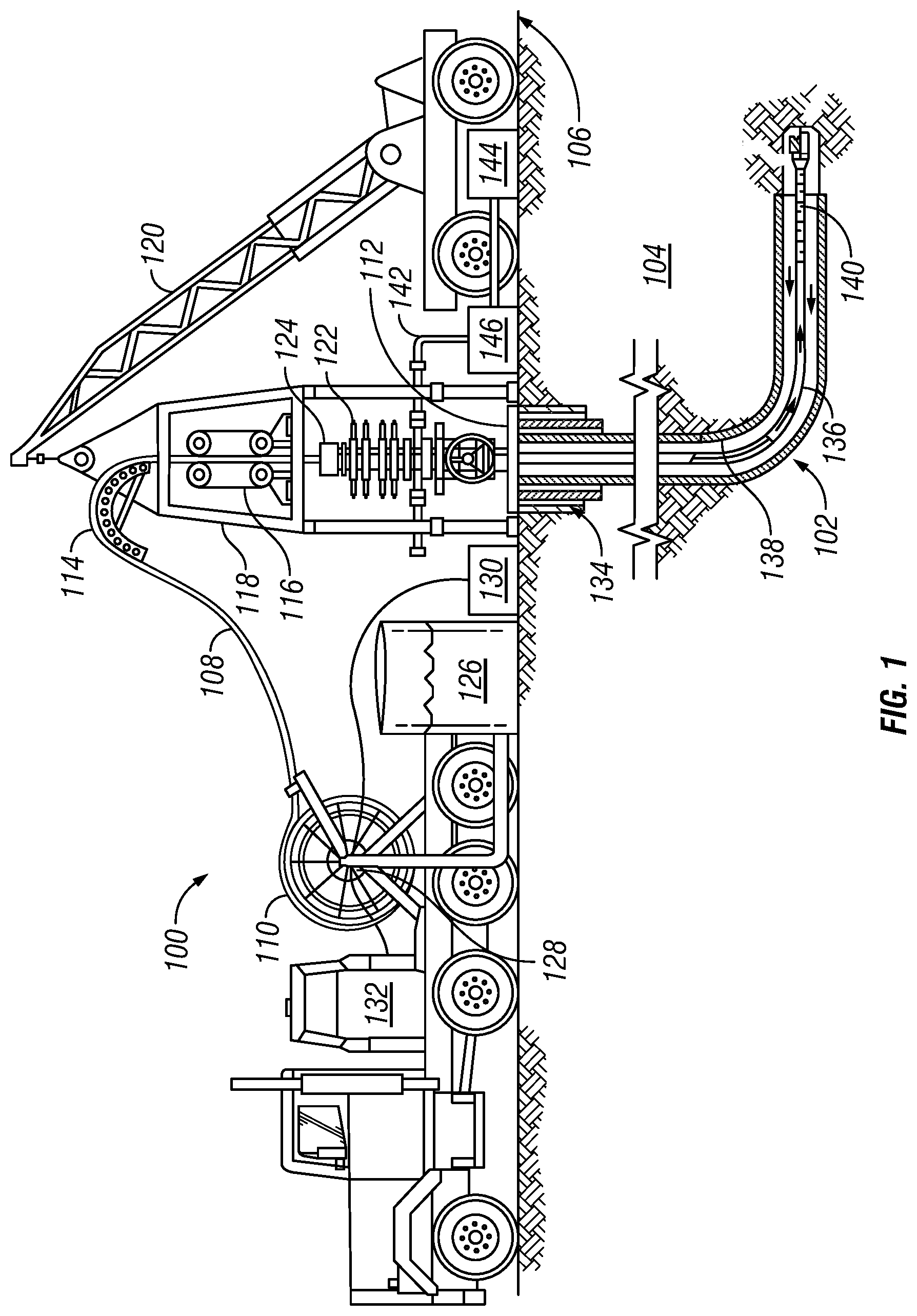
[0011] FIG. 1 is a well system 100, according to one or more embodiments. The exemplary well system 100 is utilized to produce hydrocarbons from borehole 102 extending through various earth strata in an oil and gas formation 104 located below the earth's surface 106. The borehole 102 may be formed of a single or multiple bores extending into the formation 104, and disposed in any orientation.
[0012] The well system 100 utilizes a hybrid coiled tubing system 108, as described in more detail below, to conduct various drilling, production, and well intervention operations. The hybrid coiled tubing system includes composite coiled tubing and at least one of metallic coiled tubing or piping. The hybrid coiled tubing system 108 is stored on one or more reels 110 positioned near a wellhead 112. A tube guide 114 guides the coiled tubing of the hybrid coiled tubing system 108 into an injector 116 supported on a frame assembly 118 and positioned above the wellhead 112. The tube guide 114 is used to feed and direct the coiled tubing of the hybrid coiled tubing system 108 into and out of the borehole 102. The injector 116 and the frame assembly 118 may be suspended by a conventional derrick (not shown), a support frame (not shown), or a crane 120.
[0013] The coiled tubing of the hybrid coiled tubing system 108 extends through a blowout preventer (BOP) stack 122 connected to the wellhead 112 for pressure control of the borehole 102. The BOP stack 112 may include one or more BOPs. Positioned atop the BOP stack 122 is a lubricator mechanism or one or more stuffing boxes 124, which provides the primary operational seal about the outer diameter of the coiled tubing of the hybrid coiled tubing system 108 for the retention of any pressure that may be present at or near the surface of the borehole 102. Although a land-based well system 100 is depicted in FIG. 1, the hybrid coiled tubing system 108 can be deployed from floating rigs, jackups, platforms, subsea wellheads, or any other well location. Additionally, the hybrid coiled tubing system 108 can be deployed for use on a pipeline.
[0014] A working or service fluid source 126, such as a storage tank or vessel, may supply a working fluid to the hybrid coiled tubing system 108. In particular, the fluid source 126 is in fluid communication with a fluid swivel 128 secured to reel 110 and in fluid communication with the interior of hybrid coiled tubing system 108. The fluid source 126 may supply any fluid utilized in well operations including, without limitation, drilling fluid, cement slurry, acidizing fluid, liquid water, steam, nitrogen, or some other type of fluid.
[0015] Various examples of fluids that may be provided by fluid source 126 and employed in the drilling, production, and well intervention operation described herein include air, water, oil, lubricant, friction reducer, natural gas, mist, foam, surfactant, nitrogen, various gases, drilling mud, acid, etc., or any combination thereof, which are flowed through the hybrid coiled tubing system 108 during a downhole operation. Moreover, the fluid source 126 may be in fluid communication with a pump (not shown) that pressurizes the working fluid at a select pressure, such as during high pressure pumping operation. The fluid source 126 may likewise be in communication with other surface equipment, such as mixers, blenders and the like, utilized to prepare fluids for pumping downhole via the fluid source 126. In at least one embodiment, the fluid source 126 and/or surface equipment may be adjustable in real time responsive to communications during various well operations.
[0016] The well system 100 may also include a power supply 130 and a communications hub 132 for sending signals and/or power and otherwise controlling the well operations via electric and/or optic cable deployed within the hybrid coiled tubing system 108.
[0017] The well system 100 may include one or more casing strings 134 that may be cemented in borehole 102, such as the surface, intermediate and production casings 134 shown in FIG. 1. An annulus 136 is formed between the walls of sets of adjacent tubular components, such as concentric casing strings 134 or the exterior of the hybrid coiled tubing system 108 and the inside wall 138 of borehole 102 or the casing string 134, as the case may be.
[0018] A bottom hole assembly (BHA) 140 may be suspended from the hybrid coiled tubing system 108. The well system 100 passes a fluid down the flowbore of the hybrid coiled tubing system 108 to the BHA 140. The return fluid will then pass up the annulus 136 formed between the hybrid coiled tubing system 108 and the casing string 134, completion string, or the borehole wall 138 if uncased. Fluids may also be pumped down the annulus 136 and return through the flow bore of the hybrid coiled tubing system 108. Fluids, cuttings and other debris returning to surface 106 from borehole 102 are directed by a flow line 142 to storage tanks 144 (or the fluid source 126) and/or processing systems 146, such as shakers, centrifuges and the like.
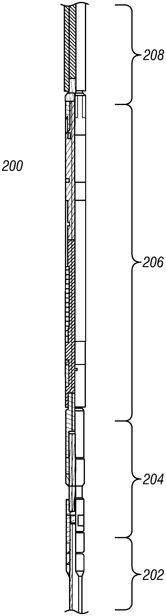
[0019] FIG. 2 is a cross-sectional view of a hybrid coiled tubing system 200, according to one or more embodiments. The hybrid coiled tubing system 200 includes composite coiled tubing 202, a connector 204, a safety valve 206, and piping 208. In some embodiments, the piping 208 may be metallic piping, such as steel piping. In other embodiments, the piping 208 may be a composite, plastic, or other material suitable for use in a pipeline or borehole. The composite coiled tubing 202 may be made of glass fiber, carbon fiber, or other composite materials known to one skilled in the art.
[0020] As shown in FIG. 2, the safety valve 206 may be positioned between the connector 204 and the piping 208. In other embodiments, the safety valve 206 may be positioned between the composite coiled tubing 202 and the connector 204, or safety valves 206 may be positioned on both sides of the connector 204. Additionally, the connector 204 may be made up of one or more components as necessary to transition between the composite coiled tubing 202 and the safety valve 206.
[0021] In at least one embodiment, the connection between the connector 204 and the composite coiled tubing 202 is a swaged connection, where the composite coiled tubing 202 is inserted into the connector 204. In other embodiments, the connection between the connector 204 and the composite coiled tubing may be a threaded connection. When using a threaded connection, the male thread may be cut into either the composite coiled tubing 202 or the connector 204. Additionally, the connection between the connector 204 and the safety valve 206 may be a threaded connection, a welded connection, or a flanged connection. Similarly the connection between the safety valve 206 and the piping 208 may be a threaded connection, a welded connection, or a flanged connection.
[0022] The safety valve 206 may be a sleeve valve, flapper valve, ball valve, or any other type of valve known to one skilled in the art that is actuated remotely from the surface via hydraulics, pneumatics, or an electromechanical actuator to control flow between the composite coiled tubing 202 and the piping 208. In other embodiments, the safety valve 206 may be actuated automatically once a preset pressure value is reached or if a specific fluid passes through the safety valve 206.
[0023] The composite coiled tubing system 200 may also include additional valves (not shown) positioned along composite coiled tubing 202 opposite the connector 204 and/or positioned along the piping 208. In other embodiments, the safety valve 206 may be omitted and the connector 204 is directly coupled to both the composite coiled tubing 202 and the piping 208. In such embodiments, the connector 204 and the piping 208 are connected via welding, a threaded connection, or a flanged connection. Additionally, some embodiments may include additional connectors (not shown) that connect the composite coiled tubing 202 to an additional section of tubing or piping (not shown), or that connect the piping 208 to an additional section of tubing or piping (not shown).
[0024] As discussed above, the composite coiled tubing system 200 may be spoolable on a reel, as shown in FIG. 1. Such a configuration allows the composite coiled tubing system 200 to be made up offsite and transported to a job site for use. In other embodiments, the piping, safety valve, and/or connector are not spoolable and the composite coiled tubing system 200 must be made up at a job site.
[0025] FIG. 3 is a cross-sectional view of a hybrid coiled tubing system 300, according to one or more embodiments. The hybrid coiled tubing system 300 includes composite coiled tubing 302, a connector 304, a safety valve 306, and metallic coiled tubing 308. Similar to the composite coiled tubing system 200 discussed above, the composite coiled tubing 302 may be made of glass fiber, carbon fiber, or other composite materials known to one skilled in the art. The metallic coiled tubing 308 may be made of steel or another metal suitable for use in a pipeline or borehole.
[0026] As shown in FIG. 3, the safety valve 306 may be positioned between the connector 304 and the metallic coiled tubing 308. In other embodiments, the safety valve 306 may be positioned between the composite coiled tubing 302 and the connector 304, or safety valves 306 may be positioned on both sides of the connector 304. Additionally, the connector 304 may be made up of one or more components as necessary to transition between the composite coiled tubing 302 and the safety valve 306. The connections between the composite coiled tubing 302, connector 304, and safety valve 306 are similar to those described above with reference to FIG. 2. However, the connection between the safety valve 308 and the metallic coiled tubing may be a swaged, threaded, welded, or flanged connection.
[0027] As discussed above, the safety valve 306 may be a sleeve valve, flapper valve, ball valve, or any other type of valve known to one skilled in the art that is actuated remotely from the surface to control flow between the composite coiled tubing 302 and the piping 308. In other embodiments, the safety valve 306 may be actuated automatically once a preset pressure value is reached or if a specific fluid passes through the safety valve 306.
[0028] The composite coiled tubing system 300 may also include additional valves (not shown) positioned along composite coiled tubing 302 opposite the connector 304 and/or positioned along the metallic coiled tubing 308. In other embodiments, the safety valve 306 may be omitted and the connector is directly coupled to both the composite coiled tubing 302 and the metallic coiled tubing 308. In such embodiments, the connector 304 and the piping 208 metallic coiled tubing are connected via welding, a swaged connection, a threaded connection, or a flanged connection. Additionally, some embodiments may include additional connectors (not shown) that connect the composite coiled tubing 302 to an additional section of tubing or piping (not shown), or that connect the metallic coiled tubing 308 to an additional section of tubing or piping (not shown).
[0029] Similar to the composite coiled tubing system 200 described above, the composite coiled tubing system 300 may be spoolable on a reel. In other embodiments, the piping, safety valve, and/or connector are not spoolable and the composite coiled tubing system 300 must be made up at the job site.
[0030] Further examples include:
[0031] Example 1 is a hybrid coiled tubing system that includes composite coiled tubing, metallic coiled tubing, and a composite coiled tubing connector coupled to and joining the composite coiled tubing and the metallic coiled tubing.
[0032] In Example 2, the embodiments of any preceding paragraph or combination thereof further include wherein a valve is coupled to and positioned between the composite coiled tubing connector and the metallic coiled tubing to control flow between the composite coiled tubing and the metallic coiled tubing.
[0033] In Example 3, the embodiments of any preceding paragraph or combination thereof further include wherein a valve is coupled to and positioned between the composite coiled tubing connector and the composite coiled tubing to control flow between the composite coiled tubing and the metallic coiled tubing.
[0034] In Example 4, the embodiments of any preceding paragraph or combination thereof further include at least one of piping, composite coiled tubing, or metallic coiled tubing that is joined to the composite coiled tubing via a second connector.
[0035] In Example 5, the embodiments of any preceding paragraph or combination thereof further include at least one of piping, composite coiled tubing, or metallic coiled tubing that is joined to the metallic coiled tubing via a second connector.
[0036] In Example 6, the embodiments of any preceding paragraph or combination thereof further include wherein the piping is composite piping.
[0037] In Example 7, the embodiments of any preceding paragraph or combination thereof further include wherein the piping is steel piping.
[0038] Example 8 is a hybrid coiled tubing system that includes composite coiled tubing, piping, and a composite coiled tubing connector coupled to and joining the composite coiled tubing and the piping.
[0039] In Example 9, the embodiments of any preceding paragraph or combination thereof further include wherein a valve is coupled to and positioned between the connector and the composite coiled tubing to control flow between the composite coiled tubing and the piping.
[0040] In Example 10, the embodiments of any preceding paragraph or combination thereof further include wherein a valve is coupled to and positioned between the connector and the piping to control flow between the composite coiled tubing and the piping.
[0041] In Example 11, the embodiments of any preceding paragraph or combination thereof further include wherein the piping includes composite piping.
[0042] In Example 12, the embodiments of any preceding paragraph or combination thereof further include wherein the piping includes steel piping.
[0043] In Example 13, the embodiments of any preceding paragraph or combination thereof further include at least one of piping, composite coiled tubing, or metallic coiled tubing that is joined to the composite coiled tubing via a second connector.
[0044] In Example 14, the embodiments of any preceding paragraph or combination thereof further include at least one of piping, composite coiled tubing, or metallic coiled tubing that is joined to the piping via a second connector.
[0045] Example 15 is a method of performing borehole servicing operations at a job site. The method includes running a tool string including a hybrid coiled tubing system into a borehole, the hybrid coiled tubing system including composite coiled tubing, either piping or metallic coiled tubing, and a coiled tubing connector coupled to and joining the composite piping and the at least one of the piping and the metallic coiled tubing. The method also includes performing servicing operations within the borehole.
[0046] In Example 16, the embodiments of any preceding paragraph or combination thereof further include a valve is coupled to and positioned between the connector and the composite coiled tubing to control flow between the composite coiled tubing and the at least one of the piping and the metallic coiled tubing.
[0047] In Example 17, the embodiments of any preceding paragraph or combination thereof further include wherein a valve is coupled to and positioned between the connector and the piping or the metallic coiled tubing to control flow between the composite coiled tubing and the at least one of the piping and the metallic coiled tubing.
[0048] In Example 18, the embodiments of any preceding paragraph or combination thereof further include wherein running the tool string comprising the hybrid coiled tubing system into the borehole comprises unspooling the hybrid coiled tubing system from a reel.
[0049] In Example 19, the embodiments of any preceding paragraph or combination thereof further include wherein running the tool string comprising the hybrid coiled tubing system into the borehole comprises connecting the composite coiled tubing to the piping or the metallic coiled tubing via a connector to make up the hybrid coiled tubing system at the job site.
[0050] In Example 20, the embodiments of any preceding paragraph or combination thereof further include wherein performing the servicing operations within the borehole comprises removing blockages and restrictions from within the borehole.
[0051] Certain terms are used throughout the description and claims to refer to particular features or components. As one skilled in the art will appreciate, different persons may refer to the same feature or component by different names. This document does not intend to distinguish between components or features that differ in name but not function.
[0052] Reference throughout this specification to "one embodiment," "an embodiment," "embodiments," "some embodiments," "certain embodiments," or similar language means that a particular feature, structure, or characteristic described in connector with the embodiment may be included in at least one embodiment of the present disclosure. Thus, these phrases or similar language throughout this specification may, but do not necessarily, all refer to the same embodiment.
[0053] The embodiments disclosed should not be interpreted, or otherwise used, as limiting the scope of the disclosure, including the claims. It is to be fully recognized that the different teachings of the embodiments discussed may be employed separately or in any suitable combination to produce desired results. In addition, one skilled in the art will understand that the description has broad application, and the discussion of any embodiment is meant only to be exemplary of that embodiment, and not intended to suggest that the scope of the disclosure, including the claims, is limited to that embodiment.
* * * * *
D00000
D00001
D00002
XML
uspto.report is an independent third-party trademark research tool that is not affiliated, endorsed, or sponsored by the United States Patent and Trademark Office (USPTO) or any other governmental organization. The information provided by uspto.report is based on publicly available data at the time of writing and is intended for informational purposes only.
While we strive to provide accurate and up-to-date information, we do not guarantee the accuracy, completeness, reliability, or suitability of the information displayed on this site. The use of this site is at your own risk. Any reliance you place on such information is therefore strictly at your own risk.
All official trademark data, including owner information, should be verified by visiting the official USPTO website at www.uspto.gov. This site is not intended to replace professional legal advice and should not be used as a substitute for consulting with a legal professional who is knowledgeable about trademark law.