Housing For Storage And Manipulation Of A Surgical Guide Wire
Wehbi; Elias
U.S. patent application number 16/911855 was filed with the patent office on 2021-01-14 for housing for storage and manipulation of a surgical guide wire. This patent application is currently assigned to The Regents of the University of California. The applicant listed for this patent is The Regents of the University of California. Invention is credited to Elias Wehbi.
| Application Number | 20210008352 16/911855 |
| Document ID | / |
| Family ID | 1000005131464 |
| Filed Date | 2021-01-14 |

| United States Patent Application | 20210008352 |
| Kind Code | A1 |
| Wehbi; Elias | January 14, 2021 |
HOUSING FOR STORAGE AND MANIPULATION OF A SURGICAL GUIDE WIRE
Abstract
A housing has a spiral passageway which contains a catheter which may be manually extracted from the housing by means of a wheel having a polygonal or otherwise textured circumferential surface and mounted on a shaft which extends through a non-circular bearing defined in an outer portion of the housing. An inner portion of the wheel extends into the spiral passageway adjacent the wire catheter and an outer portion of the wheel outwardly from the housing whereby the upper surface of the knob can be manipulated by a member of the surgical team in one direction and the wire catheter below the knob will be advanced in the opposite direction. The non-circular bearing has a generally circular outer portion in which the textured surface of the knob is only intermittently in contact with the catheter whereby the wire catheter may be advanced, and a generally linear inner portion sloping inwardly towards the catheter. When the knob's shaft is held loosely in the outer portion of the bearing, the wire catheter is free to travel. However when the knob's shaft is moved into the sloping portion of the bearing, the operator can push the knob in one direction to force the knob against the wire catheter and lock the catheter into intimate contact with the lower surface of the passageway, and in the opposite direction to retract the knob slightly away from the catheter thereby permitting limited movement of the catheter relative to the housing.
| Inventors: | Wehbi; Elias; (Newport Beach, CA) | ||||||||||
| Applicant: |
|
||||||||||
|---|---|---|---|---|---|---|---|---|---|---|---|
| Assignee: | The Regents of the University of
California Oakland CA |
||||||||||
| Family ID: | 1000005131464 | ||||||||||
| Appl. No.: | 16/911855 | ||||||||||
| Filed: | June 25, 2020 |
Related U.S. Patent Documents
| Application Number | Filing Date | Patent Number | ||
|---|---|---|---|---|
| 62866165 | Jun 25, 2019 | |||
| Current U.S. Class: | 1/1 |
| Current CPC Class: | A61M 2025/09116 20130101; A61M 25/09041 20130101 |
| International Class: | A61M 25/09 20060101 A61M025/09 |
Claims
1. Mechanism for manipulation of a surgical guide wire, comprising: a hand held housing including a spiral passageway for containing the guide wire; a disk shaped knob having a polygonal or otherwise textured circumference about an axis of rotation; an axial shaft extending along the axis of rotation of the knob and confined within a pair of opposed openings in opposite sides of the spiral passageway for securing the knob to the housing with an inner portion of the knob's textured circumference extending into the spiral passageway and into contact with the guide wire and an outer portion of the textured circumference extending out of the housing for facilitating manual rotation of the knob relative to the housing; and a non-circular bearing defined in the housing for limiting radial movement of the axial shaft relative to the housing, wherein: the non-circular bearing has an inner surface portion extending towards the guide wire for allowing the circumference of the knob to be pressed inwardly against an outer surface of the guide wire and thereby force an inner surface of the guide wire into intimate contact with an adjacent inner surface of the spiral passageway whereby the guide wire may be immobilized relative to the housing, and an outer bearing surface further from the guide wire for allowing the knob to rotate freely relative to the guide wire and the guide wire to move freely relative to the housing when the axial shaft is in contact with the outer surface of the non-circular bearing; and the inner and outer surfaces of the non-circular bearing are displaced longitudinally and radially relative to the adjacent inner surface of the spiral passageway, whereby when the surgeon presses the knob firmly in a first direction relative to the adjacent inner surface of the spiral passageway, the knob is forced downwardly towards the guide wire whereby the guide wire may be locked relative to the housing, and when the knob is allowed to move in a second direction opposite from the first direction, the pressure between the guidewire and the passageway is reduced, while still permitting the surgeon to maintain sufficient pressure between the knob and the guide wire to control the movement of the guide wire relative to the housing.
2. The mechanism of claim 1 wherein the effective coefficient of friction between the textured surface of the knob and the guide wire is greater than the coefficient of friction between the guide wire and the spiral passageway.
3. The mechanism of claim 2 wherein a longitudinal portion of the non-circular bearing is oriented at an angle relative to the spiral passageway such that when the knob is rotated in a first direction corresponding to retraction of the guide wire into the housing, the textured surface of the knob moves deeper into the spiral passageway thereby locking the guide wire relative to the spiral passageway, and when the knob is rotated in a second direction opposite to the first direction, the guide wire is no longer forced into intimate contact with the spiral passageway and the guide wire is controllably ejected from the housing.
Description
CROSS REFERENCE TO RELATED APPLICATIONS
[0001] This application is based on U.S. Provisional Application No. 62/866,165, filed on 25 Jun. 2019, which is hereby incorporated by reference in its entirety.
SUMMARY
[0002] A housing has a spiral passageway holding a catheter which may be manually extracted from the housing by means of a wheel having a polygonal or otherwise textured circumferential surface and mounted on a shaft which extends through a non-circular bearing defined in an outer portion of the housing. An inner portion of the wheel extends into the spiral passageway adjacent the wire catheter and an outer portion of the wheel extends outwardly from the housing, whereby the upper surface of the wheel can be manipulated by a member of the surgical team in one direction and the wire catheter below the knob will be advanced in the opposite direction. When the shaft is moved into a sloping portion of the non-circular bearing, the operator can push the wheel in one direction to force it against the wire catheter and lock the catheter into intimate contact with a lower surface of the passageway, and in the opposite direction to retract the wheel slightly away from the catheter thereby permitting limited movement of the catheter relative to the housing.
DRAWINGS
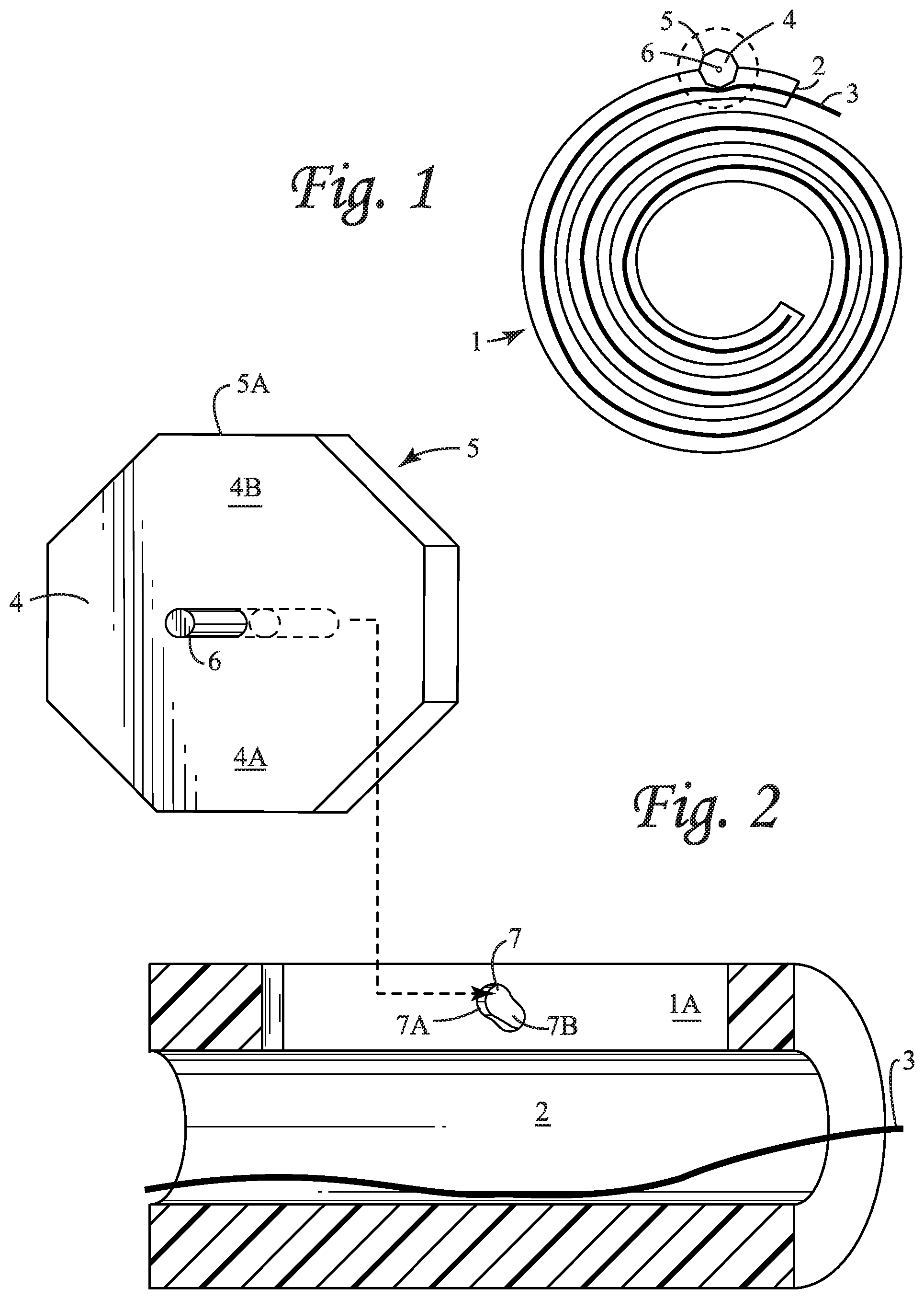
[0003] FIG. 1 is a conceptual sketch showing a spiral housing containing a catheter, with the textured circumference of a wheel in contact with the catheter and with a portion of the wheel extending into the spiral housing and into contact with the catheter.
[0004] FIG. 2 is an exploded view of the wheel and a portion of the housing of FIG. 1, showing the axle about which the wheel rotates, a non-circular bearing in the sides of the housing for supporting the axle, and a portion of the passageway holding the catheter.
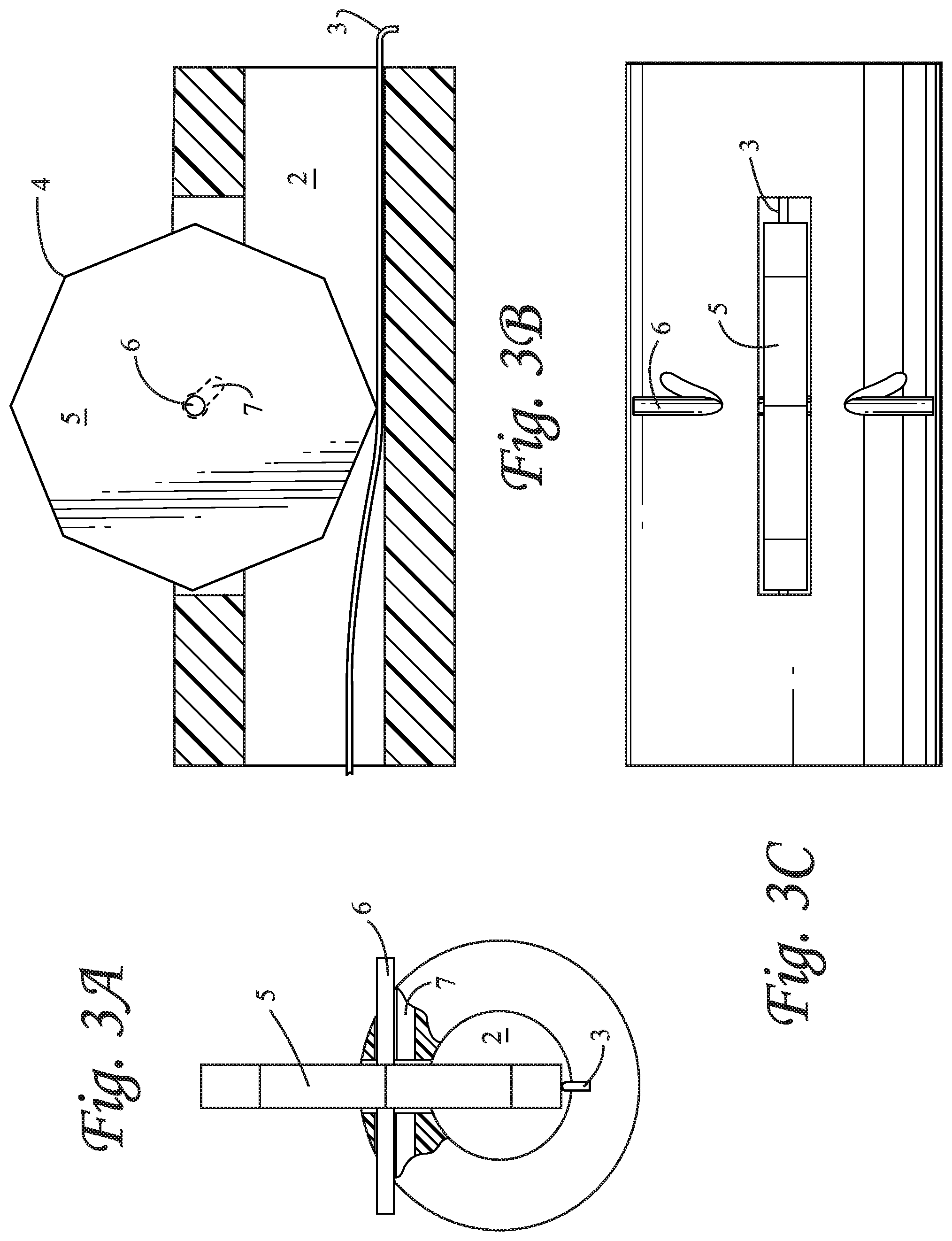
[0005] FIG. 3 comprising FIGS. 3A, 3B and 3C, are respective front, side and top views of the corresponding portion of the assembled housing and wheel of FIG. 2, in which the axle is supported in the circular upper portion of the bearing, with an apex of the wheel in contact with the catheter.
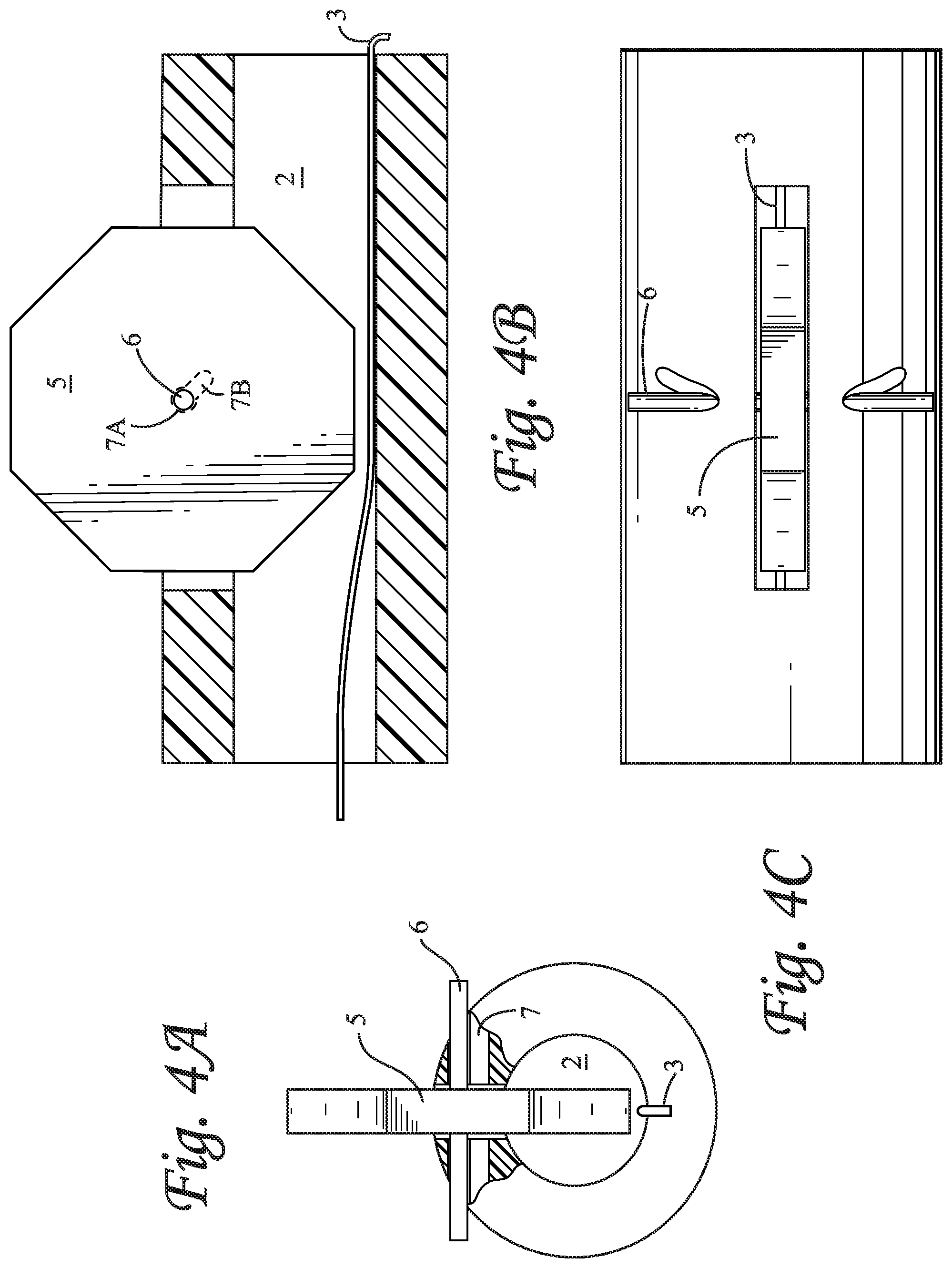
[0006] FIG. 4 is similar to FIG. 3, but with a flat surface of the wheel spaced above the catheter.
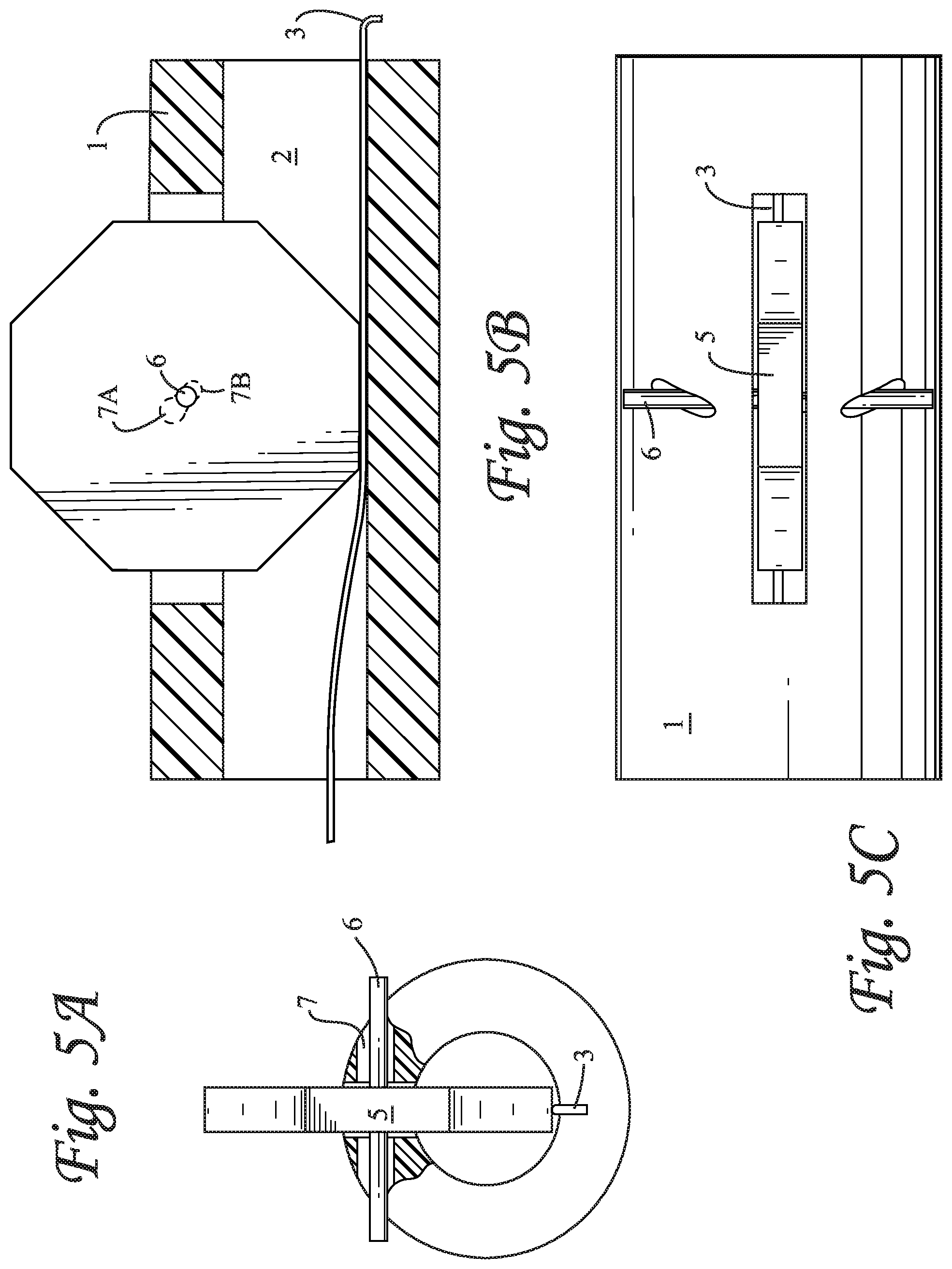
[0007] FIG. 5 is similar to FIGS. 3 and 4, but with the axle of the wheel supported in the downwardly extending portion of the bearing, with a flat surface of the wheel pressing against the catheter.
DETAILED DESCRIPTION OF AN EXEMPLARY EMBODIMENT
[0008] FIG. 1 shows a housing 1 having a spiral passageway 2 containing a wire catheter 3 which may be manually extracted from the housing by means of a wheel shaped knob 4 having a textured or polygonal circumferential surface 5 (represented in the Drawings as an 8-sided polygon). The knob is mounted coaxially on a shaft 6 which extends through a non-circular bearing 7 defined in an outer portion of the housing 8 with a lower portion 4A of the knob 4 extending into the spiral passageway 2 adjacent the wire catheter 3 and an outer (upper) portion 4B of the knob 4 extending outwardly from the housing 1 whereby the upper surface 5A of knob 4B can be manipulated by a member of the surgical team in one direction and the wire catheter 3 below the knob will be advanced in the opposite direction.
[0009] FIG. 2 is a more detailed exploded view of the knob 4 and its shaft 6, and the corresponding portion of the non-circular bearing 7 in an outer portion 1A of the housing 1 above the spiral passageway 2 containing the wire catheter 3. In particular, it will be noted that the non-circular bearing 7 has a generally circular outer portion 7A in which the textured surface of the knob 4 is only intermittently in contact with the catheter 3 whereby the wire catheter may be advanced, and a generally linear inner portion 7B sloping inwardly towards the wire catheter 3 for maintaining the textured outer surface 5 of the knob in close contact with the wire catheter 3 whereby the catheter is constrained between the opposing surfaces of the knob 4 and the spiral passageway 2.
[0010] As best seen in FIGS. 3A, 3B, and 3C and in FIGS. 4A, 4B, and 4C, when the knob's shaft 6 is held loosely in the circular outer bearing portion 7A, the wire catheter 3 is free to travel. In particular, as shown in FIGS. 3A, 3B, and 3C, when the relatively rough (e.g., high friction) surface of the knob 4 is pressing against the catheter, the relatively smooth lower surface of the spiral passageway will not oppose any motion of catheter resulting from rotation of knob 4, but rather catheter 3 will be advanced incrementally into or out of the spiral passageway.
[0011] However, as best seen in FIGS. 5A, 5B, and 5C, when the knob's shaft 6 is moved into the sloping portion 7B of the bearing, the operator can push the knob 4 in one direction to force the knob against the wire catheter 3 and lock the catheter into intimate contact with the lower surface of the passageway 2, and in the opposite direction to retract the knob 4 slightly away from the catheter, thereby permitting controlled movement of the catheter relative to the housing.
* * * * *
D00000
D00001
D00002
D00003
D00004
XML
uspto.report is an independent third-party trademark research tool that is not affiliated, endorsed, or sponsored by the United States Patent and Trademark Office (USPTO) or any other governmental organization. The information provided by uspto.report is based on publicly available data at the time of writing and is intended for informational purposes only.
While we strive to provide accurate and up-to-date information, we do not guarantee the accuracy, completeness, reliability, or suitability of the information displayed on this site. The use of this site is at your own risk. Any reliance you place on such information is therefore strictly at your own risk.
All official trademark data, including owner information, should be verified by visiting the official USPTO website at www.uspto.gov. This site is not intended to replace professional legal advice and should not be used as a substitute for consulting with a legal professional who is knowledgeable about trademark law.