Dispenser For Sheet Products, Particularly Napkins
McNulty; Peter J. ; et al.
U.S. patent application number 16/981361 was filed with the patent office on 2021-01-14 for dispenser for sheet products, particularly napkins. The applicant listed for this patent is Essity Hygiene and Health Aktiebolag. Invention is credited to John P. Devlin, Peter J. McNulty, Jeffrey S. Mekler.
| Application Number | 20210007561 16/981361 |
| Document ID | / |
| Family ID | 1000005118319 |
| Filed Date | 2021-01-14 |


| United States Patent Application | 20210007561 |
| Kind Code | A1 |
| McNulty; Peter J. ; et al. | January 14, 2021 |
DISPENSER FOR SHEET PRODUCTS, PARTICULARLY NAPKINS
Abstract
A dispenser for sheet products comprising a base, an outer shell mounted to the base, wherein the outer shell has a first portion configured to enclose a stack of sheet products to be dispensed and a second portion having a dispensing opening, the first and second portion being non-detachably and non-movably fixed relative to each other, a platen reciprocally moveable relative to the base and spring biased toward the dispensing opening, and first and second columns respectively extending from the base parallel to a movement direction of the platen on opposite sides of the platen, wherein the outer shell is detachable from the base for inserting a stack of paper products between the first and second columns onto the platen.
| Inventors: | McNulty; Peter J.; (Boston, MA) ; Devlin; John P.; (Tewksbury, MA) ; Mekler; Jeffrey S.; (Boston, MA) | ||||||||||
| Applicant: |
|
||||||||||
|---|---|---|---|---|---|---|---|---|---|---|---|
| Family ID: | 1000005118319 | ||||||||||
| Appl. No.: | 16/981361 | ||||||||||
| Filed: | March 19, 2018 | ||||||||||
| PCT Filed: | March 19, 2018 | ||||||||||
| PCT NO: | PCT/EP2018/056839 | ||||||||||
| 371 Date: | September 16, 2020 |
| Current U.S. Class: | 1/1 |
| Current CPC Class: | A47K 10/422 20130101; A47K 2010/3233 20130101; A47K 2010/3246 20130101 |
| International Class: | A47K 10/42 20060101 A47K010/42 |
Claims
1. A dispenser for sheet products comprising: a base (10); an outer shell (50) mounted to the base, wherein the outer shell has a first portion (52) configured to enclose a stack of sheet products to be dispensed and a second portion (53) having a dispensing opening (54), the first and second portion being non-detachably and non-movably fixed relative to each other; a platen (60) reciprocally moveable relative to the base (10) and spring biased toward the dispensing opening (54); and first and second columns (13, 14) respectively extending from the base (10) parallel to a movement direction of the platen (60) on opposite sides of the platen, wherein the outer shell (50) is detachable from the base (10) for inserting a stack of paper products between the first and second columns onto the platen.
2. The dispenser according to claim 1, wherein the first portion (52) comprises two pairs of opposite side walls (55) and the second portion (53) comprises a top wall (57) non-detachably and non-movably fixed to the side walls (55).
3. The dispenser according to claim 1 or 2, wherein the first (52) and second (53) portions are made of one piece.
4. The dispenser according to any one of the preceding claims, further comprising a stop (17, 18) at each of the first and second columns (13, 14), respectively provided at an end (16) of the first and second columns opposite to the base (10), the stops being configured to engage with a leading sheet product of the stack of sheet products and/or the platen (60) in an extended position.
5. The dispenser according to claim 4, wherein the stops (17, 18) are flexible parallel to the movement direction of the platen (60).
6. The dispenser according to claim 5, wherein the stops (17, 18) are more flexible parallel to the movement direction of the platen (60) in a direction towards the base (10) than a direction away from the base.
7. The dispenser according to claim 4, 5 or 6, wherein the stops (17, 18) are made of an elastic material.
8. The dispenser according to claim 7, wherein the stops (17, 18) are made of polypropylene.
9. The dispenser according to any one of claims 4 to 8, wherein the stops (17, 18) are separate parts fitted to the respective ends (16) of the first and second columns (13, 14).
10. The dispenser according to any one of the preceding claims, wherein the platen (60) has guide members (63) on opposite sides, respectively engaged with the first and second columns (13, 14).
11. The dispenser according to claim 10, wherein each guide member (63) has a pair of distanced grooves (64), respectively engaged with opposite longitudinal side edges(24, 25) of the respective first and second columns.
12. The dispenser according to any one of the preceding claims, wherein the base (10) and/or the columns (13, 14) and/or the outer shell (50) are made of a rigid plastic material, particularly of the acrylonitrile butadiene styrene group.
13. The dispenser according to any one of the preceding claims, further comprising a retention mechanism (80; 90) configured to temporarily retain the platen (60) in a retracted position while the outer shell (50) is detached from the base (10).
14. The dispenser according to claim 13, wherein the retention mechanism (80 ;90) comprises an engaging member (81; 91) and an engaged member (83; 93), wherein the engaging member is configured to be engaged with the engaged member when manually moving the platen (60) into the retracted position while the outer shell (50) is detached from the base (10).
15. The dispenser according to claim 14, wherein the engaging member (81; 91) is provided with a release portion (84; 94) configured to be engaged with the outer shell (50) to release the engaging member from the engaged member when the outer shell is attached to the base (10).
16. The dispenser according to claim 14 or 15, wherein the engaging member (81) is a latch (82) fixed relative to the base and to be engaged with a cutout or hook, as the engaged member (83), fixed relative to the platen.
17. The dispenser according to claim 14 or 15, wherein the engaging member (91) is a latch (92) fixed relative to the platen and to be engaged with a cutout or hook, as the engaged member (93), fixed relative to the base.
18. The dispenser according to any one of the preceding claims, wherein the outer shell (50) has channels (101) parallel to the movement direction of the platen respectively engaged with the first and second columns (13, 14).
19. That dispenser according to anyone of the preceding claims, wherein a width of the columns (13, 14) in a direction perpendicular to the movement direction of the platen and to a distance between the columns (13, 14) is not more than 50 mm and not less than 10 mm.
Description
CROSS REFERENCE TO RELATED APPLICATION
[0001] The present application is a U.S. national stage entry under 35 U.S.C. .sctn. 371 of, and claims priority to, International Application No. PCT/EP2018/056839, filed Mar. 19, 2018, the disclosure of which is hereby incorporated herein by reference in its entirety.
FIELD OF THE INVENTION
[0002] The present disclosure is generally related to a dispenser for sheet products, and more particularly to a dispenser configured to contain and dispense sheet products. The dispenser may be for dispensing sanitary paper sheet products such as hand towels, napkins, facial tissues, toilet paper or other wiping products in sheet form. Even more particular, the disclosure relates to so-called table top dispensers usually disposed on a table or a countertop.
BACKGROUND OF THE INVENTION
[0003] Napkins in the form of sheets of material (e.g., paper or non-woven) intended for wiping and for hygienic purposes are common commercial items (e.g., in restaurants or cafeterias) that may be provided in the form of stacks of napkins disposed in a dispenser having a dispensing opening from which individual napkins can be readily removed when needed. The dispenser for the napkins should be easy to handle, should protect the napkins until use and should be easy to move to a location where the napkins are needed, such as a table or a counter and the like.
[0004] A commonly used option is to arrange the napkins in an interfolded stack which is placed standing on a spring biased platen in a container having a dispensing opening at the top of the container. The napkins are then successively removed from the top of the stack through the dispensing opening. The platen and thereby the stack are urged towards the dispensing opening to feed the individual napkins to the dispensing opening until all of the napkins have been removed from the dispenser.
[0005] Interfolded napkins are sheets of materials arranged in a stack of superposed sheets which are each folded at least once. The sheets are interlinked in such a way that the separate folded sheets of material form a chain of sheets in which each sheet has a leading panel and a trailing panel, the trailing panel being at least partly overlapped with the leading panel of the subsequent sheet in the stack. In this manner, the individual sheets are held loosely together by means of frictional forces arising between the overlapping parts. The sheets may be dispensed from a dispenser by pulling at the leading panel of the first sheet (leading sheet) in the stack. In this manner, the first sheet is extracted at the same time as a predetermined part of the leading panel of a subsequent sheet is fed into a dispensing position in the dispenser.
[0006] Some dispensers have a lid or cover with a dispensing opening that restricts the width of the dispensed napkin in order to keep the leading panel of the next napkin to be dispensed from falling back into the dispenser. After all the napkins contained in the dispenser have been removed, the dispenser has to be refilled. For this purpose, the lid or cover is usually pivotably hinged to the body of the dispenser. Thus, the lid or cover may be opened giving access to the interior of the body for inserting a new stack of napkins. Examples of such dispensers may be found in WO 2014/037041 A1, WO 2006/132618 A1 or WO 2017/180070 A1.
[0007] Dispensers of the kind described above are generally made of a plastic material, thus being relatively inexpensive to manufacture. Nevertheless, those dispensers are made up of many parts requiring a relatively laborious assembly of the dispenser and are sometimes even double-walled (see, e.g., WO 2016/029964 A1, WO 2006/132618 A1 or WO 2017/180070 A1) leading to a relatively high material usage. Particularly for emerging markets, there is accordingly a need to further simplify those dispensers so as to decrease the manufacturing costs. At the same time, however, the dispensers need to be user-friendly regarding the dispensing process as well as the refilling process.
SUMMARY OF THE INVENTION
[0008] Accordingly, it would be desirable to provide a dispenser made up of a relatively few number of parts, that is easy and inexpensive to manufacture and still provides satisfying or even improved user-friendliness.
[0009] According to one aspect, a dispenser for sheet products is disclosed. The dispenser can be particularly configured for containing and dispensing sanitary paper products in sheet form. Examples of sanitary paper products are hand towels, paper napkins, facial tissues, toilet paper and other wiping products in sheet form. The sheet products may be made of tissue paper (ISO 12625-1) or non-woven (ISO 9092). The dispenser may consist of a base, an outer shell detachably mounted to the base and having a dispensing opening, a platen reciprocally moveable relative to the base and a biasing member such as a spring, biasing the platen away from the base and toward the dispensing opening in the outer shell. In one aspect, the dispenser may consequently consist of four structural parts only. Upon the detachment of the outer shell from the base, an upper supporting surface of the platen is readily accessible and one may easily insert or place a new stack of sheet products on the platen so that the refilling process is simplified. In order to even further improve the user-friendliness, the base may comprise first and second upright columns on opposite sides of the platen that may serve for guiding the platen in the direction of its movement and/or for aligning a new stack of sheet products on the supporting surface of the platen. The columns may be longitudinal, vertically extending from the base. Further, the columns may be flat. Furthermore, the columns may be positioned at the shorter sides of the platen, if the platen is substantially rectangular.
[0010] In this context and throughout this disclosure, an outer shell may be understood as an external, usually hard (rigid), protective and/or enclosing case or cover of the dispenser. In the same manner, the base may be understood as the bottom and/or supporting part of the outer shell. The dispensing opening in the outer shell is to be understood as the opening through which a sheet product may be withdrawn from the dispenser by a user. The base may have a supporting surface or a pedestal configured to place the base and, thus, the dispenser on a horizontal surface such as a table or countertop. In this disclosure, the platen may be a support for supporting the sheet products within the dispenser and by means of the spring pressing them against the inner surface of the outer shell surrounding the dispensing opening. The platen may be plate-shaped having a substantially square supporting surface which may in shape and/or area correspond to the shape of the sheet products or the foot print of the stack.
[0011] In accordance with another aspect, a dispenser for sheet products comprises a base and an outer shell mounted to the base. The outer shell has a first portion configured to enclose a stack of sheet products to be dispensed and a second portion having a dispensing opening. In particular, the first portion may define a space circumferentially enclosing the stack of sheet products and being open at its bottom and closed at its top by the second portion. When mounted to the base, the base closes the open bottom and supports the outer shell. The first portion and the second portion are fixed relative to each other. In this context, "fixed" is to be understood in that the portions are non-movable relative to each other and/or permanently fixed to each other in that no separation of the portions by a user is intended for refilling the dispenser. Yet, the portions may still be made from separate parts being attached to each other. In particular, "fixed relative to each other" is meant to exclude a lid having the dispensing opening and being hinged to side walls or being detachably fixed to the side walls for refilling. Rather and according to the present disclosure, the entire outer shell, including the first and second portion, is to be removed for refilling. In one example, the first portion comprises two pairs of opposite side walls which may be connected to each other at their vertical edges, and the second portion comprises a top wall fixed to the side walls, i.e., at their upper edges. In one aspect, the outer shell is made of one integral piece, particularly an injection molded part. The dispenser of this aspect further comprises a platen reciprocally moveable relative to the base and spring biased toward the dispensing opening. First and second columns, respectively, extending or protruding from the base parallel to a movement direction of the platen on opposite sides of the platen are provided. According to an example, the columns may vertically extend or protrude from the base and the base may be configured for being placed on a horizontal surface such as on a table or a countertop. The first and second columns may be separate parts that are attached or mounted to the base. Alternatively, the first and second columns may be integrated parts of the base, i.e., the first and second columns and the base are one piece, for example an injection molded part. For inserting a stack of paper products between the first and second columns onto the platen, the outer shell is detachably mounted to the base. Thus, the outer shell may translationally be removed from the base in the direction of movement of the platen and/or along the extension of the columns.
[0012] Once the outer shell is removed from the base and a new stack of sheet products is placed on the platen, the user has to temporarily hold the stack of sheet products with the platen being retained in a retracted position against the force of the spring. In this context, the retracted position may be considered as a position in which the platen is moved to a position closest to the base.
[0013] To avoid or reduce this necessity, the dispenser may further comprise a stop at each of the first and second columns, respectively, provided at an end of the first and second columns opposite to the base. In particular, the columns are attached to the base or integrally formed with the base at a first end vertically extending from the base to a second end in a longitudinal direction. The stops are provided at the second end. The stops are configured to engage with a leading sheet product of the stack of sheet products and/or the platen in an extended position. The leading sheet product of the stack of sheet products is to be considered as the first sheet product of the stack of sheet products to be dispensed through the dispensing opening, i.e., the uppermost sheet product in the stack of sheet products supported on the platen. The extended position of the platen is a position in which the platen is moved furthest away from the base by the spring without any sheet product being supported on the platen and in which the platen contacts or is engaged with a surface of the stops facing the platen. In one example, the stops may extend perpendicularly to the longitudinal extension of the columns and/or the direction of movement of the platen, i.e., horizontally, from the second end of the columns. In this example, it is no longer required to manually retain the platen in the retracted position once a new stack of sheet products has been placed on the platen, because this task is taken over by the stops engaged with the leading sheet product of the stack of sheet products and thereby holding the platen via the stack in the retracted position. A further advantage of this example is that the platen is retained in the extended position by the stops upon detachment of the outer shell from the base for refilling. Thus, the platen does not move in an uncontrolled manner when detaching the outer shell from the base.
[0014] In order to enable an easy refilling process and particularly a simple process of placing a new stack of sheet products on the platen, the stops are flexible. According to one aspect, the stops are flexible in opposite directions, but stiff enough to counteract a force exerted via a stack of sheet products by the spring biased platen and/or a force exerted directly by the spring biased platen onto the stops to thereby maintain the stack of sheet products in position on the platen and/or limit the upward movement of the platen. In a particular example, the stops are more flexible in a direction towards the base parallel to the movement direction of the platen than in a direction away from the base parallel to the movement direction of the platen. In another example, the stops are flexible in only one direction, namely the direction towards the base parallel to the movement direction of the platen. For this purpose, the stops may have a stack engaging part for engaging with the leading sheet product of the stack of sheet products or the supporting surface of the platen in an extended position and a fixing part which is fixed to the free ends of the first and second columns. The engaging part and the fixing part are connected by a hinge such as a living hinge. For more details regarding the configuration of the stops and on how to achieve flexibility, reference is made to WO 2016/029964 Al the content of which is incorporated by reference. In this context, the entire description of the "holdback members 11" of this document is incorporated by reference. In this embodiment, a new stack of sheet products may be inserted between the second ends of the columns flexing the stops toward the base and thereby pushing the platen against the force of the spring toward the retracted position. Once the stack of sheet products has passed the stops, the stops spring back and the user may release the stack. Subsequently, the platen is retained in the retracted position via the stack of sheet products with the leading sheet product of the stack of sheet products being in contact or engaged with a lower surface of the stops.
[0015] In one example, the stops are made of an elastic material such as polypropylene. The stops may be separate parts fitted to the respective end of the first and second columns. This is particularly advantageous because the first and second columns are preferably made of a hard, rigid plastic material such as acrylonitrile butadiene styrene (ABS).
[0016] So as to enable a controlled movement of the platen and thereby a simplified refilling process, the platen has guide members on opposite sides, respectively engaged with the first and second columns. In an example, the guide members may hook on the first and second columns. Thus, the guide members may guide the platen along the first and second columns in the direction of movement of the platen and limit the movement of the platen in at least one or even two direction(-s) perpendicular to the movement direction of the platen.
[0017] In one example, each guide member has a pair of distanced grooves, respectively engaged with opposite longitudinal side edges of the respective first and second columns to limit the movement of the platen in two directions perpendicular to each other and perpendicular to the movement direction of the platen.
[0018] According to an aspect, the base and/or the columns and/or the outer shell may be made of a rigid plastic material, particularly of the acrylonitrile butadiene styrene (ABS) group.
[0019] In addition or alternatively to the stops, the dispenser may further comprise a retention mechanism configured to temporarily retain the platen in the retracted (refilling) position while the outer shell is detached from the base. As previously described, it may be cumbersome to insert a new stack of sheet products and at the same time manually retain the platen in the retracted position or pushing the platen toward the retracted position while inserting a new stack. Thus, in some embodiments, the dispenser includes a retention mechanism that enables a user to manually push the platen against the spring force towards the base and thereby engage the platen with the retention mechanism with the platen being retained in the retracted position, thereby enabling easy refilling.
[0020] According to one configuration of this aspect, the retention mechanism may comprise an engaging member and an engaged member with the engaging member being configured to be engaged with the engaged member when manually moving the platen into the retracted refilling position while the outer shell is detached from the base.
[0021] In those embodiments, it may be beneficial to automatically release the retention mechanism from the platen upon attachment of the outer shell to the base so that the platen again supplies the sheet products to the dispensing opening by being urged toward the dispensing opening. In particular, the engaging member may be provided with a release portion configured to be engaged with the outer shell to release the engaging member from the engaged member when the outer shell is attached to the base.
[0022] For example, the engaging member may be a latch fixed relative to the base and to be engaged with a cutout or hook, as the engaged member, fixed relative to the platen.
[0023] Alternatively, the engaging member may be a latch fixed relative to the platen and to be engaged with a cutout or hook, as the engaged member, fixed relative to the base.
[0024] Moreover, channels may be provided on an inner surface of the outer shell, the channels engaging with the columns upon attachment of the outer shell to the base. When attaching/detaching the outer shell to/from the base, the outer shell is guided along the columns simplifying a controlled attachment/detachment.
[0025] According to an aspect, a width of the columns is within the range of 15 mm and 50 mm. In another example, the width of the columns 13, 14 is within the range of 20 mm and 40 mm. In a particular example, the width of the columns 13, 14 is between 25 mm and 35 mm.
[0026] Further aspects of the present disclosure may be found in the following description of a particular embodiment making reference to the accompanying drawings.
BRIEF DESCRIPTION OF THE DRAWINGS
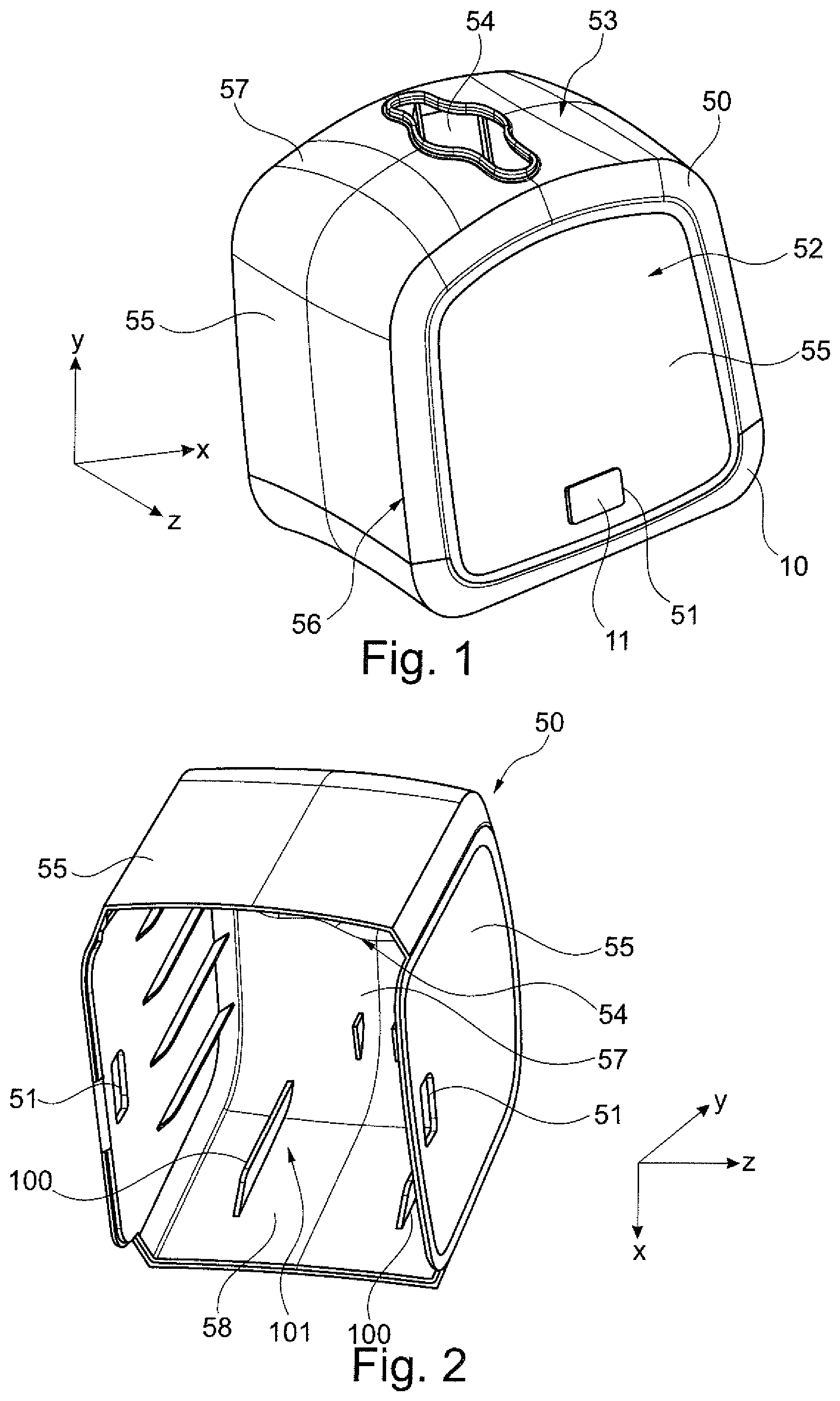
[0027] FIG. 1 shows a perspective view of a dispenser.
[0028] FIG. 2 shows a perspective view of the outer shell of the dispenser of FIG. 1.
[0029] FIG. 3 shows a perspective view of the dispenser of FIG. 1 with the outer shell being detached and embodying stops.
[0030] FIG. 4 shows a partial top view of FIG. 3.
[0031] FIG. 5 shows a perspective view of a dispenser of FIG. 1 with the outer shell of FIG. 2 being detached and embodying a first example of a retention mechanism.
[0032] FIG. 6 shows a partial enlarged perspective of the retention mechanism of the dispenser of FIG. 5.
[0033] FIGS. 7A and B show a schematic cross-section through the retention mechanism of the dispenser of FIG. 5 for describing its function.
[0034] FIG. 8 shows a perspective view of a dispenser of FIG. 1 with the outer shell of FIG. 2 being detached and embodying a second example of a retention mechanism.
[0035] FIG. 9 shows a partial enlarged perspective of the retention mechanism of the dispenser of FIG. 8.
[0036] FIGS. 10A and B show a schematic cross-section through the retention mechanism of the dispenser of FIG. 8 for describing its function.
DETAILED DESCRIPTION OF THE INVENTION
[0037] An example of a dispenser according to the present disclosure is shown in FIG. 1. The dispenser comprises a base 10 and an outer shell 50 defining a housing of the dispenser. The housing defines an interior volume configured to accommodate a stack of sheet products, such as napkins. The outer shell 50 is detachably attached to the base 10. For this purpose, the base has elastic latches 11 on opposite sides which are engaged with a respective cutout 51 in the outer shell 50 so as to releasably fix the outer shell 52 to the base 10. When the outer shell 50 is to be detached from the base 10, the latches 11, which are accessible through the cutout 51, may be pressed inward by a user to disengage them from the cutouts 51 and enable detachment of the outer shell 50.
[0038] The outer shell 50 also shown in FIG. 2 comprises a first portion 52 defining a circumferential enclosure for a stack of sheet products (not visible in FIG. 1) to be dispensed from the dispenser via a dispensing opening 54 disposed in a second portion 53 of the outer shell 50. Accordingly, the outer shell 50 may comprise two pairs of opposite side walls 55 and connected to each other at the corners or corner portions 56. Accordingly, the side walls 55 define the first portion 52, which is open at its bottom facing the base 10 and closed at its top by a top wall 57 defining the second portion 53 having the dispensing opening 54. In one embodiment, the outer shell 50 is made of rigid plastic material such as ABS. The outer shell 50 may be manufactured in an injection molding process so that the outer shell 50 is an integral one piece component.
[0039] The base 10 is shown in FIG. 3. In the illustrated example, the base 10 comprises a bottom portion 12, which is configured to correspond to a lower portion of the outer shell 50 so as to define the housing upon attachment of the outer shell 52 to the base 10.
[0040] Moreover, the base 10 comprises two columns 13, 14. In one example, the columns 13, 14 are manufactured together with the bottom portion 12 from a rigid plastic material such as ABS. Alternatively, the columns 13, 14 may be separate parts which are subsequently attached or assembled with the bottom portion 12. Yet, as with respect to the outer shell 50, the columns 13, 14 may as well be manufactured in an injection molding process together with the bottom portion 12 so that the bottom portion 12 and the columns 13, 14 are an integral one piece component.
[0041] The columns 13, 14 may, as in the illustrated example, be longitudinal elements having opposite ends 15, 16 as seen in the longitudinal direction and vertically extending or protruding from the bottom portion 12 of the base 10. In this context, the columns 13, 14 are attached to the bottom portion 12 of the base 10 at their ends 15, whereas the opposite ends 16 may be considered as free ends.
[0042] In the particular example shown in the figures, the columns 13, 14 extend or protrude from the bottom portion 12 of the base 10 and taper away from the base. Further, the columns 13, 14 are formed as flat elements in that their length in the longitudinal direction (Y direction) and their width in a width direction perpendicular to the longitudinal direction (Z direction) are larger than the thickness in the thickness direction perpendicular to the longitudinal direction and to the width direction (X direction). In an example, the width of the columns 13, 14 is within the range of 15 mm and 50 mm. In another example, the width of the columns 13, 14 is within the range of 20 mm and 40 mm. In a particular example, the width of the columns 13, 14 is between 25 mm and 35 mm, such as 25 mm.
[0043] Each of the columns 13, 14 comprises a stop 17, 18 at its free end 16. The stops 17, 18 are made of an elastic material such as polypropylene. In the illustrated example, the stops 17, 18 are made separately from the columns 13 and 14 and are attached to the free end 16 of the columns 13, 14 by means of a releasable connection, such as, and without limitation, a snap fit connection (e.g., hooks 19 of the stops 17, 18 engaged with cutouts 20 at the free end 16 of the columns 13, 14).
[0044] The stops 17, 18 are flexible in a direction towards the base 10 (bottom portion 12). To put it differently, the stops 17, 18 may be flexed at a film (living) hinge 21 about an axis 22 parallel to the width direction (Z direction) of the columns 13, 14.
[0045] The stops 17, 18 are prevented from being flexed upward beyond the position shown in FIG. 3 (substantially parallel orientation to the platen 60 or more particularly the supporting surface 61 of the platen). Accordingly, the stops 17, 18 are flexible or elastic in only one direction, namely a direction toward the bottom portion 12 of the base 10 or toward an inner surface of each of the columns 13, 14. At least, however, flexing upward is not intended and the stops 17, 18 are less flexible in an upward direction than in a downward direction. In order to achieve the required and intended flexibility, the configuration of the hinge as well as the manufacturing process (e.g., injection molding) are of importance. For details in regard of the configuration of the stops, reference is made to WO 2016/029964 A1.
[0046] The dispenser comprises a platen 60. The platen 60 has an upward supporting surface 61 on which the sheet products are to be placed. The platen 60 is reciprocally movable along the columns 13, 14 in a direction indicated by the double arrow in FIG. 3 (Y direction). In particular, the platen 60 is movable between a retracted position close to the base 10 or the bottom portion 12 of the base 10 as shown in FIG. 3 and an extended position in which the upwardly facing supporting surface 61 of the platen 60 is in contact with a downwardly facing surface of the stops 17, 18 limiting further upward movement of the platen 60 beyond the stops 17, 18.
[0047] In order to continuously feed the sheet products towards the dispensing opening 54 upon withdrawal of the sheet products from the dispenser, the platen 60 is urged towards the dispensing opening 54 by a spring 70. The spring 70 is disposed between a downward surface 62 of the platen 60 and an upward surface 23 of the bottom portion 12 of the base 10.
[0048] Further, at the sides of the columns 13, 14 the platen 60 is provided with a guide member 63 engaging with (e.g., hooking on) the columns 13, 14 and guiding the platen along the columns 13, 14 in the Y direction and limiting the movement in the width direction (Z direction) and/or the X direction. In the illustrated example, the guide member 63 is in the form of a T-groove guide with the platen 60 having the T-grooves and the respective column respectively engaging the T-groove. To put it differently, a pair of distanced grooves 64 is provided and the grooves 64 are respectively engaged with opposite longitudinal side edges 24, 25 of the respective first and second columns.
[0049] In the following, reference is made to the refilling process of the dispenser shown in FIGS. 1 to 4.
[0050] When all the sheet products contained in the dispenser are dispensed and new sheet products need to be filled into the dispenser, the user first pushes the latches 11 to disengage them from the cutouts 51. Subsequently, the user is enabled to detach the outer shell 50 from the base 10 substantially in a translational movement along the Y direction.
[0051] In this situation, the upward surface (supporting surface) 61 of the platen 60 is in an extracted position in which the upward surface 61 is in abutting contact with a surface of the stops 17, 18 facing the upward surface 61 of the platen 60. Accordingly, the platen 60 is maintained in the extracted position by the stops 17, 18.
[0052] The user then grips a stack of sheet products and inserts the stack from the top in FIG. 3 between the columns 13, 14 flexing the stops 17, 18 at the hinge 21 about the axis 22 towards the inner surfaces of the columns 13, 14 so that the stack of sheet products may pass the stops 17, 18. During this process, the stack contacts the supporting surface 61 of the platen 60 and the platen 60 is pushed downward toward the bottom portion 12 of the base 10 against the spring force of the spring 70 and guided along the columns 13 and 14 by the guide member 63 in a controlled manner.
[0053] Once the leading sheet product (uppermost sheet product) in the stack of sheet products has passed the stops 17, 18, the stops 17, 18 spring back due to their elasticity. Once the user releases the stack of sheet products, the surfaces of the stops 17, 18 facing the leading sheet product come in contact with the leading sheet product when the stack of sheet products is pushed upward by the platen 60 being urged upwardly by the spring 70. Consequently, the stack of sheet products is maintained in position and the outer shell 50 may easily be attached to the base 10 by engaging the latches 11 with the cutouts 51. Further and as visible from FIG. 2, the outer shell 50 has ribs 100 on its inner surface 58 forming channels 101 which are respectively engaged with the columns 13, 14 during attachment of the outer shell 50 to the base 10. Accordingly, the outer shell 50 is guided by the channels 101 along the columns 13, 14 during attachment/detachment of the outer shell 50 to/from the base 10.
[0054] A further dispenser is shown in FIGS. 1, 2 and 5 to 7. The only difference as compared to the dispenser described with respect to FIGS. 1 to 4 is that the stops 17, 18 are omitted and instead a retention mechanism 80 is embodied. The retention mechanism 80 is provided to temporarily retain the platen 60 in the retracted position for refilling when the outer shell 50 is detached from the base 10.
[0055] For this purpose, the retention mechanism 80 comprises an engaging member 81 and an engaged member. The engaging member 81 may, for example, be fixed to the bottom portion 12 of the base 10. The engaging member 81 may be made of bent sheet metal, thus being flexible and elastic. The engaging member 81 may have a latch 82. The engaging member 81 may further have a release portion 84 configured to engage with an inner surface 58 of the outer shell 50 upon attachment of the outer shell 50 to the base 10.
[0056] The engaged member may be in the form of a cutout 83 formed in a side surface of the platen 60.
[0057] Accordingly, a user may place a new stack of sheet products on the supporting surface 61 of the platen 60 and push the platen 60 downward against the spring force of the spring 70. Once the platen 60 reaches the retracted position as shown in FIG. 5, the latch 82 is first pressed inward and subsequently springs back to engage with the cutout 83. Accordingly, the platen 60 is retained in the retracted position, even if the user releases the platen 60. As a result, the stack of sheet products can easily be placed on the supporting surface resting between the columns 13 and 14 and on the upward supporting surface 61 enabling easy attachment of the outer shell 50.
[0058] When attaching the outer shell 50 as shown in FIGS. 7A and B by translationally moving the outer shell 50 along the arrow A in FIG. 7A, an inner surface 58 of the outer shell 50 comes in contact with the release portion 84 of the engaging member 81 and pushes the engaging member 81 inward whereby the latch 82 is released from the cutout 83. Consequently, the platen 60 may move upward as shown by the arrow B in FIG. 7B being urged by the spring 17.
[0059] An alternative retention mechanism 90, which may be used instead of the retention mechanism 80, is shown in the dispenser depicted in FIGS. 1, 2 and 7 to 10. The retention mechanism 90 is provided to temporarily retain the platen 60 in the retracted position for refilling when the outer shell 50 is detached from the base 10.
[0060] For this purpose, the retention mechanism 90 comprises an engaging member 91 and an engaged member. The engaging member 91 may, for example, be fixed to the platen 60. The engaging member 91 is one piece with the platen 60 and integrally formed in an injection molding process. The engaging member 91 may have one or more flexible latches 92. The engaging member 91 may further have a release portion 94 configured to engage with an inner surface 58 of the outer shell 50 or a ramp 59 at the inner surface 58 of the outer shell 50 upon attachment of the outer shell 50 to the base 10.
[0061] The engaged member may be in the form of one or more hooks 93 formed at the bottom portion 12 of the base 10.
[0062] Accordingly, a user may place a new stack of sheet products on the supporting surface 61 of the platen 60 and push the platen 60 downward against the spring force of the spring 70. Once the platen 60 reaches the retracted position as shown in FIG. 9, the latches 92 are first pressed inward by the slanted surfaces 94 of the hooks 93 and subsequently spring back to engage with the hooks 93. Accordingly, the platen 60 is retained in the retracted position, even if the user releases the platen 60. As a result, the stack of sheet products may be placed on the supporting surface and rests between the columns 13 and 14 and on the supporting surface 61 enabling easy attachment of the outer shell 50.
[0063] When attaching the outer shell 50 as shown in FIGS. 10A and B by translationally moving the outer shell 50 along the arrow A in FIG. 10A, a ramp 59 on an inner surface 58 of the outer shell 50 comes in contact with the release portion 94 of the engaging member 91 and pushes the engaging member 91 inward (see arrow C in FIG. 10A), whereby the latches 92 are released from the hooks 93. Consequently, the platen 60 may move upward as shown by the arrow B in FIG. 10B being urged by the spring 17.
[0064] The use of the stops 17, 18 and of the retention mechanisms 80; 90 has been disclosed separately in the illustrated example embodiments. Yet, it will be apparent that the stops and a retention mechanism may as well be embodied in one dispenser. Thus, the present disclosure is not limited to the above examples, but various modifications and alterations are conceivable within the scope of the appended claims.
* * * * *
D00000
D00001
D00002
D00003
D00004
XML
uspto.report is an independent third-party trademark research tool that is not affiliated, endorsed, or sponsored by the United States Patent and Trademark Office (USPTO) or any other governmental organization. The information provided by uspto.report is based on publicly available data at the time of writing and is intended for informational purposes only.
While we strive to provide accurate and up-to-date information, we do not guarantee the accuracy, completeness, reliability, or suitability of the information displayed on this site. The use of this site is at your own risk. Any reliance you place on such information is therefore strictly at your own risk.
All official trademark data, including owner information, should be verified by visiting the official USPTO website at www.uspto.gov. This site is not intended to replace professional legal advice and should not be used as a substitute for consulting with a legal professional who is knowledgeable about trademark law.