Mitt For Manually Handled Object Drop Safety
SALISBURY; Richard ; et al.
U.S. patent application number 16/510638 was filed with the patent office on 2021-01-14 for mitt for manually handled object drop safety. The applicant listed for this patent is TECHNIQUE SOLUTIONS PTY LTD. Invention is credited to David SALISBURY, Richard SALISBURY.
| Application Number | 20210007422 16/510638 |
| Document ID | / |
| Family ID | 1000004215124 |
| Filed Date | 2021-01-14 |


| United States Patent Application | 20210007422 |
| Kind Code | A1 |
| SALISBURY; Richard ; et al. | January 14, 2021 |
MITT FOR MANUALLY HANDLED OBJECT DROP SAFETY
Abstract
A mitt for manually handled object drop safety has a fabric covering and a wrist cuff which may be worn like a loose-fitting glove to catch accidentally dropped manually handled objects. The covering has a penetrable interlace of flat bands defining a plurality of insertion points at intersections therebetween through which typically objects such as fasteners such as bolts, nuts and the like may be inserted during manual handling.
| Inventors: | SALISBURY; Richard; (Tullamarine, AU) ; SALISBURY; David; (Tullamarine, AU) | ||||||||||
| Applicant: |
|
||||||||||
|---|---|---|---|---|---|---|---|---|---|---|---|
| Family ID: | 1000004215124 | ||||||||||
| Appl. No.: | 16/510638 | ||||||||||
| Filed: | July 12, 2019 |
| Current U.S. Class: | 1/1 |
| Current CPC Class: | A41D 13/081 20130101 |
| International Class: | A41D 13/08 20060101 A41D013/08 |
Claims
1. A mitt having a loose-fitting fabric covering interfacing a wrist cuff at a proximal end thereof, the covering comprising a penetrable interlace of orthogonal flat material bands defining a plurality of insertion points at intersections therebetween through which manually handled objects may be pressed in use.
2. A mitt as claimed in claim 1, wherein each band alternates over and under each other consecutive orthogonal band.
3. A mitt as claimed in claim 2, wherein the bands have a width of greater than 1 cm and wherein edges of parallel adjacent bands lie less than 3 mm apart.
4. A mitt as claimed in claim 1, wherein the material bands are elastic.
5. A mitt as claimed in claim 1, wherein the penetrable interlace perpendicularly intersects a longitudinal axis of the cuff.
6. A mitt as claimed in claim 5, wherein the penetrable interlace is rectangular.
7. A mitt as claimed in claim 6, wherein the covering has top, bottom and sides with respect to the longitudinal axis and wherein the penetrable interlace forms at least a part of a front of the covering and is bounded by the top, bottom and sides.
8. A mitt as claimed in claim 7, wherein a top edge of the front lies closer to the longitudinal axis as compared to a bottom edge thereof.
9. A mitt as claimed in claim 1, wherein the covering comprises a transparent or semi-transparent screen for viewing an interior of the covering in use.
10. A mitt as claimed in claim 9, wherein the screen comprises a mesh.
11. A mitt as claimed in claim 9, wherein at screen locates at a top of the covering to lie at a rear of the hand inserted therein in use.
12. A mitt as claimed in claim 11, wherein at least one of the sides and a bottom of the covering comprises a further transparent or semi-transparent screen.
13. A mitt as claimed in claim 1, wherein the cuff comprises a tightenable outer cuff band.
14. A mitt as claimed in claim 13, wherein the outer cuff band has an end which doubles back through a buckle and the end has an inner fastener surface which fastens to an outer fastener surface of the band thereunderneath.
15. A mitt as claimed in claim 14, wherein the fastener surfaces comprise hook and loop fasteners.
16. A mitt as claimed in claim 15, wherein the cuff comprises an inner flexible sleeve surrounded by the outer cuff band.
17. A mitt as claimed in claim 15, further comprising a further penetrable interlace of orthogonal flat material bands.
18. A mitt as claimed in claim 15, wherein the penetrable interlace is located at a front of the covering and wherein the further penetrable interlace is located at a side of the covering and wherein the mitt further comprises a screen at a top of the mitt and a further screen at a bottom of the mitt.
19. A mitt as claimed in claim 1, wherein the penetrable interlace comprises at least four bands in each orthogonal orientation, thereby defining at least nine insertion points at respective intersections therebetween.
20. The method of securing manually handled objects using a mitt as claimed in claim 1, the method comprising donning the mitt on a hand, tightening the cuff and pressing a manually handled object through one of the plurality of insertion points of the penetrable interlace of the orthogonal flat material bands.
Description
FIELD OF THE INVENTION
[0001] This invention relates to a mitt for manually handled object drop safety.
BACKGROUND OF THE INVENTION
[0002] Drop safety equipment of various configurations exist including those comprising lanyards, tethers and the like and which are designed to catch accidentally dropped objects such as tools.
[0003] The present invention seeks to provide drop safety equipment, which will overcome or substantially ameliorate at least some of the deficiencies of the prior art, or to at least provide an alternative.
[0004] It is to be understood that, if any prior art information is referred to herein, such reference does not constitute an admission that the information forms part of the common general knowledge in the art, in Australia or any other country.
SUMMARY OF THE DISCLOSURE
[0005] There is provided herein a mitt having a fabric covering interfacing a wrist cuff. The fabric covering is configured to cover the thumb and forefingers of a hand inserted through the cuff in use. The covering is not close-fitting, thereby allowing the relatively free manipulation of the fingers and thumb of the hand therein.
[0006] The covering comprises a penetrable interlace of orthogonal flat material bands. Intersections between orthogonal and adjacent material bands define various insertion points which dilate when objects such as bolts, nuts and the like are pressed therethrough, thereby allowing objects to be pushed into and pulled from an interior of the covering.
[0007] However, edges of adjacent bands lie close together such that the insertion points remain small and constricted by default, being smaller than a minimum dimension of the object.
[0008] As such, in use, the mitt may be donned to cover forefingers and thumb of the hand and the wrist cuff tightened for securement. An object, such as a bolt, can be pushed through any one of the available insertion points of the penetrable interlace so as to allow the user to hold the object by hand to affix or release or otherwise use the object externally.
[0009] However, should the object be accidentally dropped, the covering will catch the object including in that the interlace of orthogonal flat material bands can prevent the object from falling through the interlace.
[0010] In embodiments, the penetrable interlace may be arranged at the front of the covering at the fingertips, thereby allowing the pushing of objects forwardly therethrough.
[0011] In embodiments, the covering may comprise further penetrable interlaces, such as a side penetrable interlace facing an inner side of the hand, thereby allowing sideways access of objects or alternatively allowing for the insertion of tools therethrough, such as spanners. In this way, an object such as a bolt can be held in one hand through the front interlace whereas a spanner may be inserted through the side interlace to tighten the bolt in the usual manner.
[0012] In embodiments, the covering comprises at least one flexible and transparent/semitransparent screen for viewing the interior of the covering. The screen may comprise a mesh, thereby enhancing breathability of the mitt. The screen may be located at a top of the covering so as to locate above are adjacent a rear of the hand, thereby allowing the viewing of the object therein from above. In embodiments the covering may comprise further screens, such as at at least one side and bottom of the covering to allow for further viewpoints of the object therein.
[0013] In embodiments, the covering comprises a side penetrable interlace and screens both above and below. As such, the mitt can be worn on either hand with one of the screens locating above irrespectively.
[0014] The covering may further comprise external tether points and which may be load rated and from which lanyards may be used to secure tools, such as spanners and the like. In this embodiment, the cuff may hold the mitt to the hand if jerked by a dropped tethered tool.
[0015] According to one aspect, there is provided a mitt having a loose-fitting fabric covering interfacing a wrist cuff at a proximal end thereof, the covering comprising a penetrable interlace of orthogonal flat material bands defining a plurality of insertion points at intersections therebetween through which manually handled objects may be pressed in use.
[0016] Each band may alternate over and under each other consecutive orthogonal band.
[0017] The bands may have a width of greater than 1 cm and edges of parallel adjacent bands may lie less than 3 mm apart.
[0018] The material bands may be elastic.
[0019] The penetrable interlace may perpendicularly intersect a longitudinal axis of the cuff.
[0020] The penetrable interlace may be rectangular.
[0021] The covering may have top, bottom and sides with respect to the longitudinal axis and wherein the penetrable interlace forms at least a part of a front of the covering and may be bounded by the top, bottom and sides.
[0022] A top edge of the front may lie closer to the longitudinal axis as compared to a bottom edge thereof.
[0023] The covering may comprise a transparent or semi-transparent screen for viewing an interior of the covering in use.
[0024] The screen may comprise a mesh.
[0025] A screen may locate at a top of the covering to lie at a rear of the hand inserted therein in use.
[0026] At least one of the sides and a bottom of the covering may comprise a further transparent or semi-transparent screen.
[0027] The cuff may comprise a tightenable outer cuff band.
[0028] The outer cuff band may have an end which doubles back through a buckle and the end may have an inner fastener surface which fastens to an outer fastener surface of the band thereunderneath.
[0029] The fastener surfaces may comprise hook and loop fasteners.
[0030] The cuff may comprise an inner flexible sleeve surrounded by the outer cuff band.
[0031] The mitt may further comprise a further penetrable interlace of orthogonal flat material bands.
[0032] The penetrable interlace may be located at a front of the covering and wherein the further penetrable interlace may be located at a side of the covering and wherein the mitt further may comprise a screen at a top of the mitt and a further screen at a bottom of the mitt.
[0033] The penetrable interlace may comprise at least four bands in each orthogonal orientation, thereby defining at least nine insertion points at respective intersections therebetween.
[0034] According to another aspect, there is provided a method of securing manually handled objects using the mitt, the method comprising donning the mitt on a hand, tightening the cuff and pressing a manually handled object through one of the plurality of insertion points of the penetrable interlace of the orthogonal flat material bands.
[0035] Other aspects of the invention are also disclosed.
BRIEF DESCRIPTION OF THE DRAWINGS
[0036] Notwithstanding any other forms which may fall within the scope of the present invention, preferred embodiments of the disclosure will now be described, by way of example only, with reference to the accompanying drawings in which:
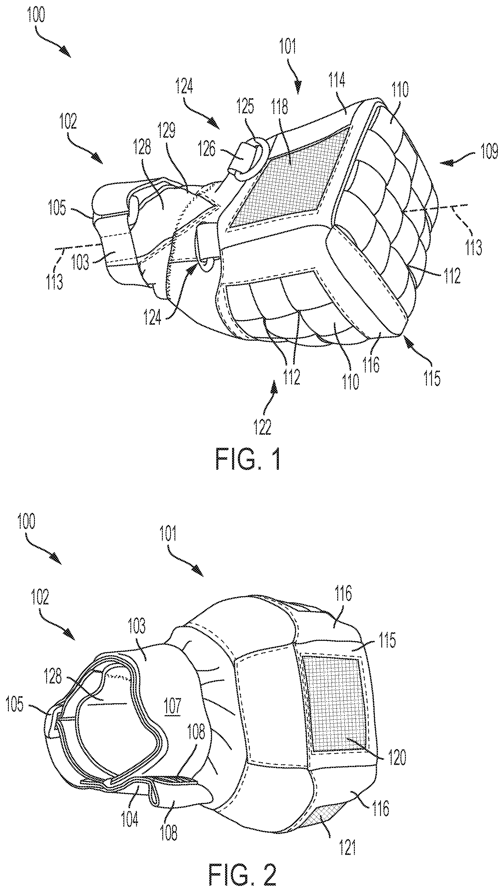
[0037] FIG. 1 shows a perspective view of a mitt in accordance with an embodiment;
[0038] FIG. 2 shows an underside perspective view of the mitt;
[0039] FIG. 3 illustrates the donning of the mitt;
[0040] FIG. 4 illustrates the use of the mitt while manipulating objects by hand;
[0041] FIG. 5 illustrates the way in which the mitt may catch accidentally dropped objects; and
[0042] FIG. 6 illustrates the way in which objects within the mitt may be viewed and/or tools inserted in accordance with embodiments.
DESCRIPTION OF EMBODIMENTS
[0043] A mitt 100 comprises a fabric covering 101 interfacing a wrist cuff 102.
[0044] For orientational referencing, top and derivatives thereof will generally refer to locations at a rear/back of the hand and bottom and derivatives thereof at the palm of the hand. Similarly, front and derivatives thereof relate to being at or perpendicularly facing the forefingers and inner side and derivatives thereof refer to at or facing the first forefinger and thumb.
[0045] When a hand is inserted through the cuff 102 in the manner shown in FIGS. 3 and 4, the covering 101 is configured to cover the thumb and forefingers in a loose-fitting manner, thereby allowing the manipulation of the fingers to manually handle objects.
[0046] The wrist cuff 102 may comprise a tightenable outer cuff band 103. An end 104 of the outer cuff band 103 may double back through a buckle 105 and the end 104 may comprise an inner fastener surface 106 which fastens to an outer fastener surface 107 of the band 103. The end 104 may have a pull terminus 108 extending beyond the inner fastener surface 106 to facilitate strapping and unstrapping.
[0047] The fastener surfaces 106, 107 may comprise hook and loop fasteners. The larger outer fastener surface 107 may comprise loop fasteners to reduce abrasion at the cuff 102 as compared to having hook fasteners.
[0048] The cuff 102 may comprise an inner flexible sleeve 128 enclosed by the outer cuff band 103. The inner flexible sleeve 128 may be increasingly exposed by a V-neck 129 as is shown in FIG. 1.
[0049] The covering 101 may comprise a penetrable interlace 109 of orthogonal flat material bands 110. The flat material bands 110 are interlaced 109 in that each band 110 alternates over and under each other consecutively adjacent orthogonal bands 110 as is shown in FIG. 1. Furthermore, edges of adjacent parallel bands 110 may lie close together as similarly shown in FIG. 1, such as by less than 5 mm, 3 mm or 1 mm in embodiments.
[0050] The material bands 110 may be elastic. Portions of the covering 101 other than the penetrable interlace 109 may comprise canvas or similar material.
[0051] Intersections between the bands 110 therefore define penetrable insertion points 112 through which objects may be pushed. The bands 110 may be configured to provide a plurality of insertion points 112, thereby allowing user choice of location through which to press an object.
[0052] In a preferred embodiment, the interlace 109 comprises more than three bands in each orthogonal orientation, thereby providing at least four insertion points 112. In the embodiment shown, the interlace 109 at the front of the mitt 100 comprises four bands in each orientation, thereby providing up to nine central insertion points 112.
[0053] The width of the bands 110 may be varied, including depending on the type and therefore size of the object being handled. However, the width of the bands 110 may be greater than 1 cm, 1.5 or 2 cm embodiments. Furthermore, the width or height of the interface 109 may be greater than 4 cm, 7 cm or 10 cm in embodiments thereby providing a sufficiently large area through which to push objects and various insertion points 112.
[0054] When handling an object 111 such as a fastener such as a bolt, nut, nail or the like, or another type of object, the mitt 100 is donned by inserting the hand through the wrist cuff 102 in the manner shown in FIG. 3.
[0055] The object 111 may be pushed through one of the available insertion points 112 of the penetrable interlace 109 in the manner shown in FIG. 4.
[0056] As is illustrated in FIG. 4, the bands 110 move apart at any one of the multiple insertion points 112 of the penetrable interlace 109, thereby allowing the object 111 to be passed therethrough.
[0057] As such, the object 111 may be gripped by the hand within the covering 101 and passed through any one of the multiple insertion points 112 of the penetrable interlace 109 for handling, such as screwing into a fastener aperture 113 as shown in FIG. 3 for example.
[0058] However, should the object 111 be accidentally dropped, the covering 101 will catch the object 111 therein in the manner shown in FIG. 5.
[0059] As edges of parallel adjacent bands 110 of the penetrable interlace 109 run close together, the insertion points 112 remain small (such as by, for example, comprising a maximum diameter of less than 5 mm, 3 mm or 1 mm in various embodiments) thereby preventing the object 111 from falling therethrough, even under inertia from falling a short distance from the hand.
[0060] In embodiments, the penetrable interlace 109 may be substantially square and arranged at the front of the covering 110 orthogonally facing the fingertips (i.e. in that that the penetrable interlace 109 perpendicularly intersects a longitudinal axis 113 through the cuff 102), thereby allowing objects 111 to pass forwardly the penetrable interlace 109 in front of the hand.
[0061] In embodiments the covering 110 comprises a top 114, bottom 115 and sides 116 and the penetrable interlace 109 forms a front surrounded by the forward edges of the top 114, bottom 115 and sides 116.
[0062] As can be seen from FIG. 4, a top edge of the front of the covering 110 may lie closer to the longitudinal axis 113 of the cuff 102 as compared to a bottom edge thereof. In other words, the vertical midpoint 117 may be beneath the longitudinal axis 113 of the cuff 102 thereby allowing greater accommodation for the manipulation of the fingers.
[0063] The covering 101 may comprise a flexible and transparent or semi-transparent screen 118. Whereas the screen 118 may comprise transparent plastic in embodiments, in a preferred embodiment the screen 118 comprises a mesh which is both semitransparent and breathable.
[0064] The screen 118 may be at the top of the covering 101 so as to locate at a rear surface of the hand so as to provide a top view 119 into an interior of the covering 101 as is illustrated in FIG. 6.
[0065] In embodiments the covering 101 may comprise further semitransparent screens such as a bottom semitransparent screen 120 and/or a side transparent screen. As such, the user may view an interior of the covering 101 additionally or alternatively from the bottom and/or side of the mitt 100.
[0066] In embodiments the covering 101 comprises a further penetrable interlace 122 similarly comprising orthogonal flat material bands 110. The further penetrable interlace 122 may locate at the inner side of the hand (i.e. generally coplanar with surfaces of the thumb and first forefinger). The further penetrable interlace 122 may be orthogonally arranged with respect to the penetrable interlace 109 at the front of the covering 110.
[0067] In this way, objects may be accessed through sides of the covering 110 also.
[0068] Furthermore, in embodiments, a tool 123 such as a spanner or the like may be inserted through the further side penetrable interlace 122 to interface the object 111 penetrating through the front penetrable interlace 109. The tool 123 may be manipulated with a free hand while the other hand holds the object 111.
[0069] In embodiments, the mitt 100 comprises top and bottom screens 118 and both the front penetrable interlace 109 and the side penetrable interlace 122. In this way, the mitt may be worn on either the left or the right hand wherein one of the screens 118 locates at the top of the hand irrespectively.
[0070] In embodiments the mitt 100 comprises at least one tether point 124 which may comprise a D-shackle 125 retained within a material loop 126. The material loop 126 may be sufficiently wide, such as more than 1 cm, 1.5 cm or 2 cm in embodiments for adequate securement of the D shackle 125 for load rating, so as to, for example, be able to arrest a 2 kg object such as an electric power drill dropped through 1.5 m.
[0071] A lanyard 127 may connect the tether point 124 to the tool 123 in the manner shown in FIG. 6. As is shown in FIG. 1, tether points 124 may be provided at both sides of the mitt 100 so as to be able to secure tools 123 from either side or simultaneously from both sides of the hand in use.
[0072] The foregoing description, for purposes of explanation, used specific nomenclature to provide a thorough understanding of the invention. However, it will be apparent to one skilled in the art that specific details are not required in order to practise the invention. Thus, the foregoing descriptions of specific embodiments of the invention are presented for purposes of illustration and description. They are not intended to be exhaustive or to limit the invention to the precise forms disclosed as obviously many modifications and variations are possible in view of the above teachings. The embodiments were chosen and described in order to best explain the principles of the invention and its practical applications, thereby enabling others skilled in the art to best utilize the invention and various embodiments with various modifications as are suited to the particular use contemplated. It is intended that the following claims and their equivalents define the scope of the invention.
[0073] The term "approximately" or similar as used herein should be construed as being within 10% of the value stated unless otherwise indicated.
* * * * *
D00000
D00001
D00002
D00003
XML
uspto.report is an independent third-party trademark research tool that is not affiliated, endorsed, or sponsored by the United States Patent and Trademark Office (USPTO) or any other governmental organization. The information provided by uspto.report is based on publicly available data at the time of writing and is intended for informational purposes only.
While we strive to provide accurate and up-to-date information, we do not guarantee the accuracy, completeness, reliability, or suitability of the information displayed on this site. The use of this site is at your own risk. Any reliance you place on such information is therefore strictly at your own risk.
All official trademark data, including owner information, should be verified by visiting the official USPTO website at www.uspto.gov. This site is not intended to replace professional legal advice and should not be used as a substitute for consulting with a legal professional who is knowledgeable about trademark law.