Method Of Controlling Plurality Of Feeding Apparatuses Sequentially Connected To Image Forming Apparatus
Ishikawa; Naoki
U.S. patent application number 16/913816 was filed with the patent office on 2021-01-07 for method of controlling plurality of feeding apparatuses sequentially connected to image forming apparatus. The applicant listed for this patent is CANON KABUSHIKI KAISHA. Invention is credited to Naoki Ishikawa.
| Application Number | 20210006683 16/913816 |
| Document ID | / |
| Family ID | |
| Filed Date | 2021-01-07 |


View All Diagrams
| United States Patent Application | 20210006683 |
| Kind Code | A1 |
| Ishikawa; Naoki | January 7, 2021 |
METHOD OF CONTROLLING PLURALITY OF FEEDING APPARATUSES SEQUENTIALLY CONNECTED TO IMAGE FORMING APPARATUS
Abstract
When a feeding apparatus of a first type is connected to a first mounting surface, a processor outputs, to the feeding apparatus of the first type via a first signal terminal, a control signal. The feeding apparatus of the first type is connected to a second mounting surface, the control unit outputs, to a feeding apparatus of a second type via the second signal terminal, a control command for controlling the feeding apparatus of the first type. When the feeding apparatus of the first type is connected to the second mounting surface, the feeding apparatus of the second type outputs, to the feeding apparatus of the first type via a fourth signal terminal, a control signal based on a control command for controlling the feeding apparatus of the first type outputted from an image forming apparatus.
| Inventors: | Ishikawa; Naoki; (Kashiwa-shi, JP) | ||||||||||
| Applicant: |
|
||||||||||
|---|---|---|---|---|---|---|---|---|---|---|---|
| Appl. No.: | 16/913816 | ||||||||||
| Filed: | June 26, 2020 |
| Current U.S. Class: | 1/1 |
| International Class: | H04N 1/12 20060101 H04N001/12; H04N 1/00 20060101 H04N001/00; H04N 1/23 20060101 H04N001/23 |
Foreign Application Data
| Date | Code | Application Number |
|---|---|---|
| Jul 1, 2019 | JP | 2019-123132 |
Claims
1. An image forming system comprising an image forming apparatus and a feeding apparatus configured to feed a sheet to the image forming apparatus, the image forming apparatus comprising: a first mounting surface to which either a feeding apparatus of a first type or a feeding apparatus of a second type can be connected; a first signal terminal configured to output a control signal from the image forming apparatus to a feeding apparatus of a first type in a case where the first type feeding apparatus is connected to a first mounting surface; a second signal terminal configured to communicate a signal with the feeding apparatus of the second type in a case where the feeding apparatus of the second type is connected to the first mounting surface; an acceptance port configured to accept a sheet fed from the feeding apparatus of the first type or of the second type; at least one first processor configured to generate a control signal to be outputted to the first signal terminal or the second signal terminal, the feeding apparatus of the second type comprising: a second mounting surface to which the feeding apparatus of the first type can connect; a third signal terminal configured to be connected with the second signal terminal via a first cable; and a fourth signal terminal configured to output a control signal with the feeding apparatus of the first type in a case where the feeding apparatus of the first type is connected to the second mounting surface, and wherein the feeding apparatus of the first type comprises: a fifth signal terminal configured to be connected to the first signal terminal of the image forming apparatus via a second cable in a case where the feeding apparatus of the first type is connected to the first mounting surface of the image forming apparatus, and connected to the fourth signal terminal of the feeding apparatus of the second type via the second cable in a case where the feeding apparatus of the first type is connected to the second mounting surface of the feeding apparatus of the second type, and wherein the at least one first processor is configured to in a case where the feeding apparatus of the first type is connected to the first mounting surface, output, to the feeding apparatus of the first type via the first signal terminal, a control signal, and in a case where the feeding apparatus of the first type is connected to the second mounting surface, output, to the feeding apparatus of the second type via the second signal terminal, a control command for controlling the feeding apparatus of the first type, and the feeding apparatus of the second type is configured to in a case where the feeding apparatus of the first type is connected to the second mounting surface, output, to the feeding apparatus of the first type via the fourth signal terminal, a control signal based on a control command for controlling the feeding apparatus of the first type outputted from the image forming apparatus.
2. The image forming system according to claim 1, wherein the feeding apparatus of the second type comprises at least one second processor configured to convert a control command for controlling the feeding apparatus of the first type received from the image forming apparatus into a control signal that the feeding apparatus of the first type can receive, and to output the control signal to the feeding apparatus of the first type from the fourth signal terminal.
3. The image forming system according to claim 1, wherein the at least one first processor is configured to, based on a signal of the first signal terminal or the second signal terminal, discriminate a type of a feeding apparatus connected to the first mounting surface, and wherein the at least one first processor discriminates whether the feeding apparatus of the first type is connected or the feeding apparatus of the second type is connected to the first mounting surface based on a discrimination result.
4. The image forming system according to claim 3, wherein when the at least one first processor discriminates that the feeding apparatus of the second type is connected to the first mounting surface, transmits, to the feeding apparatus of the second type via the second signal terminal, a query signal for querying whether the feeding apparatus of the first type is connected to the second mounting surface of the feeding apparatus of the second type, receives from the feeding apparatus of the second type a response signal in response to the query signal, and based on the response signal, discriminates whether the feeding apparatus of the first type is connected to the second mounting surface of the feeding apparatus of the second type.
5. An image forming apparatus to which a manual feeding unit and a feeding deck respectively for feeding sheet can be connected, the apparatus comprising: an image forming section configured to form an image on a sheet fed from the manual feeding unit and the feeding deck; and at least one first processor configured to, in a case where the manual feeding unit is connected to the image forming apparatus, output a signal for controlling operation of the manual feeding unit, and in a case where the manual feeding unit is connected to the feeding deck connected to the image forming apparatus, control the feeding deck to cause the feeding deck to control the manual feeding unit.
6. The image forming apparatus according to claim 5, wherein in a case where a plurality of the feeding deck are connected in series to the image forming apparatus, and the manual feeding unit is connected to the most upstream feeding deck among the plurality of feeding decks, the at least one processor controls the most upstream feeding deck to cause the most upstream feeding deck to control the manual feeding unit.
7. The image forming apparatus according to claim 6, wherein the at least one processor is further configured to: determine that a feeding stage designated by a print job that is inputted is connected to the most upstream feeding deck is a manual feeding unit; and in a case where the designated feeding stage is a manual feeding unit connected to the most upstream feeding deck, transmit to the most upstream feeding deck a control command for controlling the manual feeding unit.
8. The image forming apparatus according to claim 7, wherein the at least one processor is further configured to: establish communication with respect to each of the plurality of feeding decks connected in series a feeding deck connected beside the image forming apparatus among the plurality of feeding decks, and obtain information indicating each feeding stage of the plurality of feeding decks; and based on the obtained information, determine whether a feeding stage designated by the print job is a manual feeding unit connected to the most upstream feeding deck.
9. The image forming apparatus according to claim 8, wherein the at least one processor is further configured to, based on the information respectively obtained from the plurality of feeding decks, make a query to a feeding deck, among the plurality of feeding decks, to which there is a possibility that the another feeding apparatus is connected, the query being for information relating to the another feeding apparatus.
10. A feeding apparatus connected to an upstream side of an image forming apparatus in a sheet conveyance direction, the apparatus comprising: a communication section configured to communicate with the image forming apparatus; and at least one processor configured to, in a case where a manual feeding unit is connected, control the manual feeding unit based on a control command transmitted from the image forming apparatus and received by the communication section, and in a case where the manual feeding unit is connected to the image forming apparatus, not control the manual feeding unit.
11. The feeding apparatus according to claim 10, wherein in a case where another feeding apparatus is connected downstream of the feeding apparatus in a conveyance direction of the sheet, the at least one processor controls the manual feeding unit by receiving from the another feeding apparatus a control command to the manual feeding unit received from the image forming apparatus by the another feeding apparatus.
12. The feeding apparatus according to claim 11, wherein the other feeding apparatus is directly connected to the image forming apparatus by a communication line, and the other feeding apparatus and the feeding apparatus are directly connected by a communication line, and the at least one processor is transferred via the communication line from the image forming apparatus to the feeding apparatus.
13. The feeding apparatus according to claim 10, further comprising a driving circuit configured to drive a driving source arranged in the manual feeding unit.
14. The feeding apparatus according to claim 10, wherein the at least one processor is further configured to detect whether or not the manual feeding unit is connected to the feeding apparatus and when it is detected that the manual feeding unit is connected to the feeding apparatus, the communication section notifies the image forming apparatus that the manual feeding unit is connected.
Description
BACKGROUND OF THE INVENTION
Field of the Invention
[0001] The present invention relates to a method for controlling a plurality of feeding apparatuses sequentially connected to an image forming apparatus.
Description of the Related Art
[0002] There are cases in which in order to execute post-processing such as folding processing or stapling and punching processing, a plurality of post-processing apparatuses are connected sequentially downstream in a sheet conveyance direction to an image forming apparatus. In recent years, there is demand for a plurality of feeding apparatuses to be connected upstream in a sheet conveyance direction. In particular, there is a demand for the supply of a wide variety of sheets and the supply of a large number of sheets in POD (print on-demand). U.S. Pat. No. 4,980,780 proposes connecting in parallel a plurality of feeding apparatus to an image forming apparatus.
[0003] In the invention described in U.S. Pat. No. 4,980,780, a plurality of post-processing apparatuses and a plurality of feeding apparatuses are being controlled via a common signal line. Note that there are feeding apparatus that are to be directly connected to an image forming apparatus. For convenience of explanation, such feeding apparatuses will be referred to as manual feeding units. With a manual feeding unit, it is not possible for other feeding apparatuses to communicate with the image forming apparatus via a common signal line. For example, if the image forming apparatus and the manual feeding unit are directly connected via another signal cable other than the common signal line, the image forming apparatus should be able to control such a manual feeding unit. However, in the case where a manual feeding unit is connected sequentially together with a plurality of feeding apparatuses to the image forming apparatus, the length of the signal cable differs depending on the number of feeding apparatuses present between the image forming apparatus and the manual feeding unit. In other words, the user must prepare a specific one of a plurality of lengths of signal cables, and usability suffers. Hypothetically, when another feeding apparatus is added between the image forming apparatus and the manual feeding unit to the image forming apparatus to which the manual feed unit is attached, a longer signal cable becomes necessary.
SUMMARY OF THE INVENTION
[0004] The present invention provides an image forming system comprising an image forming apparatus and a feeding apparatus configured to feed a sheet to the image forming apparatus. The image forming apparatus comprises: a first mounting surface to which a feeding apparatus of a first type and a feeding apparatus of a second type can be connected; a first signal terminal configured to output a control signal from the image forming apparatus to a feeding apparatus of a first type in a case where the first type feeding apparatus is connected to a first mounting surface; a second signal terminal configured to communicate a signal with the feeding apparatus of the second type in a case where the feeding apparatus of the second type is connected to the first mounting surface; an acceptance port configured to accept a sheet fed from the feeding apparatus of the first type or of the second type; at least one processor configured to generate a control signal to be outputted to the first signal terminal or the second signal terminal. The feeding apparatus of the second type comprises a second mounting surface to which the feeding apparatus of the first type can connect; a third signal terminal configured to be connected with the second signal terminal via a first cable; and a fourth signal terminal configured to output a control signal with the feeding apparatus of the first type in a case where the feeding apparatus of the first type is connected to the second mounting surface. The feeding apparatus of the first type comprises a fifth signal terminal configured to be connected to the first signal terminal of the image forming apparatus via a second cable in a case where the feeding apparatus of the first type is connected to the first mounting surface of the image forming apparatus, and connected to the fourth signal terminal of the feeding apparatus of the second type via the second cable in a case where the feeding apparatus of the first type is connected to the second mounting surface of the feeding apparatus of the second type. The at least one processor is configured to in a case where the feeding apparatus of the first type is connected to the first mounting surface, output, to the feeding apparatus of the first type via the first signal terminal, a control signal, and in a case where the feeding apparatus of the first type is connected to the second mounting surface, output, to the feeding apparatus of the second type via the second signal terminal, a control command for controlling the feeding apparatus of the first type. The feeding apparatus of the second type is configured to in a case where the feeding apparatus of the first type is connected to the second mounting surface, output, to the feeding apparatus of the first type via the fourth signal terminal, a control signal based on a control command for controlling the feeding apparatus of the first type outputted from the image forming apparatus.
[0005] Further features of the present invention will become apparent from the following description of exemplary embodiments (with reference to the attached drawings).
BRIEF DESCRIPTION OF THE DRAWINGS
[0006] FIGS. 1A to 1C are views illustrating a front of an image forming system.
[0007] FIGS. 2A to 2C are views illustrating a back of the image forming system.
[0008] FIG. 3 is a view illustrating an internal configuration of the image forming system.
[0009] FIG. 4 is a view illustrating controllers of the image forming system.
[0010] FIG. 5 is a view illustrating controllers of the image forming system.
[0011] FIG. 6 is a view illustrating controllers of the image forming system.
[0012] FIG. 7 is a flow chart illustrating a feeding apparatus connection confirmation.
[0013] FIG. 8 is a block diagram illustrating functions of a CPU.
[0014] FIG. 9 is a flow chart illustrating the feeding apparatus connection confirmation.
[0015] FIG. 10 is a block diagram illustrating functions of a CPU.
[0016] FIG. 11 is a flow chart illustrating a method for executing print jobs.
[0017] FIG. 12 is a flow chart illustrating sheet feed control in a feeding deck.
[0018] FIG. 13 is a view illustrating controllers of the image forming system.
[0019] FIG. 14 is a view illustrating controllers of the image forming system.
[0020] FIG. 15 is a view illustrating controllers of the image forming system.
[0021] FIG. 16 is a flow chart illustrating a feeding apparatus connection confirmation.
[0022] FIG. 17 is a flow chart illustrating a feeding apparatus connection confirmation.
[0023] FIG. 18 is a flow chart illustrating sheet feed control in a feeding deck.
DESCRIPTION OF THE EMBODIMENTS
[0024] Hereinafter, embodiments will be described in detail with reference to the attached drawings. Note, the following embodiments are not intended to limit the scope of the claimed invention. Multiple features are described in the embodiments, but limitation is not made an invention that requires all such features, and multiple such features may be combined as appropriate. Furthermore, in the attached drawings, the same reference numerals are given to the same or similar configurations, and redundant description thereof is omitted. The lowercase alphabet letters appended to the end of reference signs are appended in order to distinguish the same type or similar elements. Accordingly, when matters common to the plurality of elements are described, the lowercase alphabet letters on the end of the reference signs will be omitted.
First Embodiment
[0025] <Image Forming System>
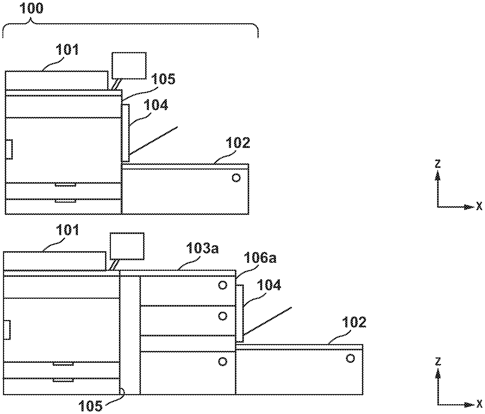
[0026] As FIG. 1A illustrates, an image forming apparatus 101 of an image forming system 100 includes a mounting surface 105. A manual feeding unit 104 is connected to an upper part of the mounting surface 105. The manual feeding unit 104 may be referred to as a manual feeding apparatus. The manual feeding unit 104 includes a tray, and feeds a sheet placed on the tray by a user to the image forming apparatus 101. A long sheet feeding deck 102 is connected to a lower part of the mounting surface 105. The long sheet feeding deck 102 feeds a long size type sheet to the image forming apparatus 101. The image forming apparatus 101 forms an image on the sheet and then discharges the sheet.
[0027] As FIG. 1B illustrates, a feeding deck 103a in which many sheets can be contained may be connected to the mounting surface 105 of the image forming apparatus 101. A connecting surface 106a of the feeding deck 103a is of a shape compatible with the mounting surface 105 of the image forming apparatus 101. Therefore, the long sheet feeding deck 102 and the manual feeding unit 104 can be connected to the connecting surface 106a of the feeding deck 103a. The feeding deck 103a supplies the image forming apparatus 101 with not only sheets held in its own storage compartment, but also sheets fed from the long sheet feeding deck 102 and the manual feeding unit 104. In the following description, when similar or common matters are illustrated, the lowercase alphabet letters on the end of the reference signs may be omitted.
[0028] As FIG. 1C illustrates, a feeding deck 103b of the same type as the feeding deck 103a can be connected to the connecting surface 106a of the feeding deck 103a. A connecting surface 106b of the feeding deck 103b is compatible with forms associated with the mounting surface 105 and the connecting surface 106a. Therefore, the long sheet feeding deck 102 and the manual feeding unit 104 can also be connected to the connecting surface 106b. The feeding deck 103b, via the feeding deck 103a, supplies the image forming apparatus 101 with not only sheets held in its own storage compartment, but also sheets fed from the long sheet feeding deck 102 and the manual feeding unit 104. The feeding deck 103a transfers sheets supplied from the feeding deck 103b to the image forming apparatus 101.
[0029] <Cables>
[0030] FIG. 2A is a view from a rear side of the image forming system 100 illustrated in FIG. 1A. The image forming apparatus 101 includes a terminal 21a and a terminal 22a. The manual feeding unit 104 includes a terminal 24. The terminal 21a is connected to the terminal 24 via a cable 17b. The image forming apparatus 101 supplies the manual feeding unit 104 with control signals and power via the cable 17b. The long sheet feeding deck 102 includes a terminal 23. The terminal 23 is connected to the terminal 22a via a cable 17a. The image forming apparatus 101 supplies the long sheet feeding deck 102 with control signals and power via the cable 17a. Note that the terminal 21 may be a connector connecting a cable 17. The terminal 21 may be arranged within an apparatus housing, and does not need to be arranged at the back of the housing.
[0031] The image forming apparatus 101 may communicate with the long sheet feeding deck 102 by serial communication. In this case, the cable 17a may include a clock line and a control line for serial communication. On the other hand, the terminal 24 may be directly connected to a motor and a sensor arranged within the manual feeding unit 104. In this case, since the image forming apparatus 101 and the manual feeding unit 104 do not execute communication, the cable 17b does not need to be equipped with a clock line and a control line for serial communication. The cable 17b, for example, may include a drive line through which the drive current to the motor is supplied and a signal line for conveying a detection signal of the sensor.
[0032] FIG. 2B and FIG. 2C are views from a rear side of the image forming system 100 illustrated in FIG. 1B and FIG. 1C. As FIG. 2B and FIG. 2C illustrate, the feeding deck 103a includes a terminal 25b connected to the terminal 22a of the image forming apparatus 101 via the cable 17a. In addition, the feeding deck 103a includes a terminal 22b to be connected, via a cable 17c, to the terminal 23 of the long sheet feeding deck 102 or a terminal 25c of the feeding deck 103b. The feeding deck 103a includes a terminal 21b connected to the terminal 24 of the manual feeding unit 104 via the cable 17b. The feeding deck 103a converts control commands received via the cable 17a to generate control signals (the drive current and the driving pulse), and supplies the manual feeding unit 104 with these via the cable 17b.
[0033] The feeding deck 103b includes the terminal 25c to be connected to the terminal 22b of the feeding deck 103a via the cable 17c. The feeding deck 103b includes a terminal 22c to be connected to the terminal 23 of the long sheet feeding deck 102 via a cable 17d. The feeding deck 103b includes a terminal 21c to be connected to the terminal 24 of the manual feeding unit 104 via the cable 17b. The feeding deck 103b converts a control command received via the cables 17a and 17c to generate a control signal (a drive current), and supplies it to the manual feeding unit 104 via the cable 17b.
[0034] Here, the feeding deck 103a may be the same product as the feeding deck 103b. In addition, the terminals 21a to 21c may have compatibility. Similarly, the terminals 22a to 22c may have compatibility. The terminals 23, 25b, and 25c may have compatibility, too. In this case, the cables 17a, 17c, and 17d may have compatibility, too.
[0035] In this way, the cables 17a to 17d each connect two adjacent apparatuses. Thus, the length of the cables 17a to 17d may be comparably short. For example, when directly connecting the terminal 21a of the image forming apparatus 101 to the terminal 24 of the manual feeding unit 104 in the connection configurations illustrated in FIG. 2B and FIG. 2C, a longer cable is required. This is because there are one or more feeding decks 103 between the image forming apparatus 101 and the manual feeding unit 104. In the present embodiment, the control signals that had been directly supplied from the image forming apparatus 101 to the manual feeding unit 104 and the long sheet feeding deck 102 are indirectly supplied to these from the image forming apparatus 101. Specifically, the feeding deck 103 directly connected to the manual feeding unit 104 and the long sheet feeding deck 102 supplies the control signals to the manual feeding unit 104 and the long sheet feeding deck 102. Thereby, the cables connected to the manual feeding unit 104 and the long sheet feeding deck 102 become shorter.
[0036] <Internal Mechanism>
[0037] FIG. 3 illustrates an internal mechanism of the image forming system 100. The image forming apparatus 101, the long sheet feeding deck 102, the feeding deck 103, and the manual feeding unit 104 each include a feeding stage 111. The feeding stage 111 is a container or a tray containing many sheets P. A feeding roller 12 is a roller which pulls up a sheet P contained in the feeding stage 111 to feed it to a conveyance path. A conveyance roller 13 conveys the sheet P from upstream to downstream on the conveyance path. Note that a conveyance path of the feeding apparatus positioned upstream is connected to a conveyance path of the feeding apparatus positioned downstream in conveyance direction of the sheet P. For example, an outlet 19d of the conveyance path of the manual feeding unit 104 and an outlet 19e of the conveyance path of the long sheet feeding deck 102 are connected to an inlet 18c of the conveyance path of the feeding deck 103b. An outlet 19c of the conveyance path of the feeding deck 103b is connected to an inlet 18b of the conveyance path of the feeding deck 103a. The outlet 19b of the conveyance path of the feeding deck 103a is connected to an inlet 18a of the conveyance path of the image forming apparatus 101. In this way, the sheet P is handed over from the outlet 19 to the inlet 18. Note that a sheet sensor 11 which detects a sheet P is arranged at the inlet 18.
[0038] The image forming apparatus 101 includes an imaging forming unit 15. The imaging forming unit 15 forms an image on the sheet P fed from one of the feeding stages 111. A discharge roller 14 discharges the sheet P from an outlet 19a to a discharge tray 16. For example, the image forming method of the imaging forming unit 15 may be any of an electrographic method, an electrostatic recording method, an inkjet method, or the like.
[0039] <Control Unit>
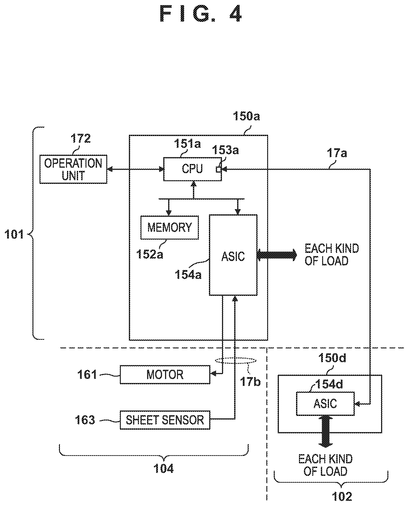
[0040] FIG. 4 illustrates a control unit 150a of the image forming apparatus 101 in the image forming system 100, a control unit 150d of the long sheet feeding deck 102, and a group of loads in the manual feeding unit 104 illustrated in FIG. 1A (FIG. 2A). The control unit 150a includes a CPU 151a, a memory 152a, and an ASIC 154a. The CPU 151a is configured with at least one possessor circuitry and controls the image forming system 100 by executing the control program stored in the ROM of the memory 152a. The ASIC 154a includes a driving circuit that drives a motor that drives the imaging forming unit 15, the conveyance roller 13, and the like arranged in the image forming apparatus 101. The ASIC 154a drives each kind of load in accordance with control commands outputted from the CPU 151a. The CPU 151a accepts a user instruction via an operation unit 172. CPU is an abbreviation for Central Processing Unit. ASIC is an abbreviation for Application Specific Integrated Circuit. ROM is an abbreviation for Read-Only Memory.
[0041] The CPU 151a is connected via the cable 17a to an ASIC 154d within the control unit 150d arranged in the long sheet feeding deck 102. The CPU 151a may execute serial communication with the ASIC 154d via an IO port 153a and the cable 17a to execute transmission and reception of commands and responses. The IO port 153a may be the serial communication port for executing serial communication. Note that IO is an abbreviation for Input and Output. The ASIC 154a arranged in the control unit 150a of the image forming apparatus 101 drives a motor 161 of the manual feeding unit 104 via the cable 17b and receives the detection signal of a sheet sensor 163. Note that the manual feeding unit 104 does not include a control unit such as a CPU or an ASIC.
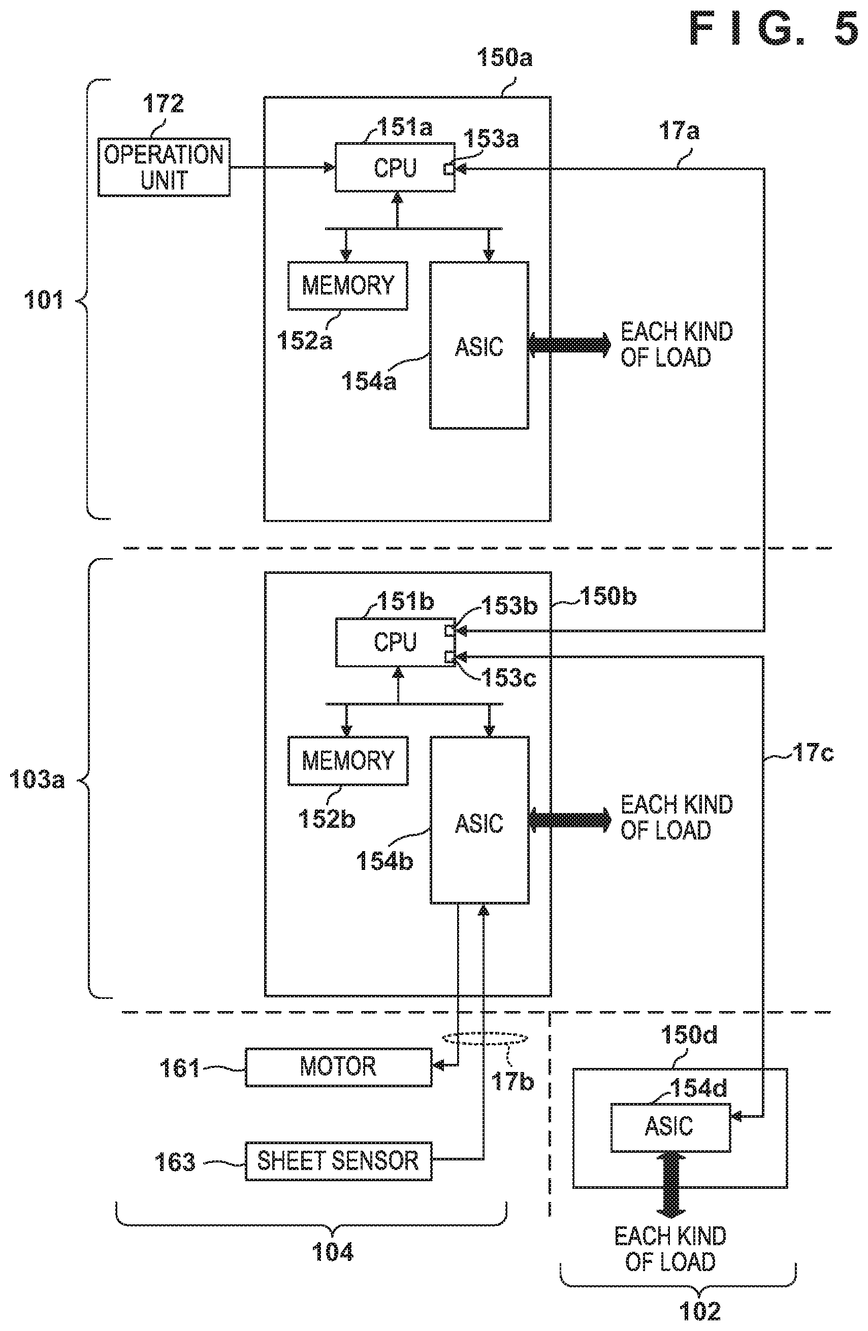
[0042] FIG. 5 illustrates control units and a group of loads of the image forming system 100 illustrated in FIG. 1B (FIG. 2B). The feeding deck 103a includes a control unit 150b. The control unit 150b includes a CPU 151b, a memory 152b, and an ASIC 154b. The CPU 151b is configured with at least one possessor circuitry and controls the feeding deck 103a, the manual feeding unit 104, and the long sheet feeding deck 102 by executing a control program stored in the ROM of the memory 152b. In other words, the control unit 150b controls the manual feeding unit 104 and the long sheet feeding deck 102 instead of the control unit 150a. The ASIC 154b includes a driving circuit that drives a motor that drives the feeding roller 12, the conveyance roller 13, and the like arranged in the feeding deck 103. The ASIC 154b drives each kind of load in accordance with control commands outputted from the CPU 151b.
[0043] The CPU 152b is connected to the ASIC 154d of the control unit 150d arranged in the long sheet feeding deck 102 via an IO port 153c and the cable 17c. The CPU 152b executes serial communication with the ASIC 154d via the cable 17c to execute transmission and reception of commands and responses. Furthermore, the CPU 151b is connected to the CPU 151a of the image forming apparatus 101 via an IO port 153b and the cable 17a, and executes serial communication. The CPU 152b transfers to the ASIC 154d a feeding command for the long sheet feeding deck 102 transmitted from the CPU 151a. The IO ports 153b and 153c may be serial communication ports for executing serial communication.
[0044] The CPU 151b transmits to the ASIC 154b a control signal to drive the motor 161 based on a feeding command of the manual feeding unit 104 transmitted from the CPU 151a. The ASIC 154b generates a drive current or a driving pulse based on this control signal and drives the motor 161 by supplying it to the motor 161. Also, the ASIC 154b outputs a detection result indicated by the detection signal of the sheet sensor 163 on the CPU 151b. The CPU 151b transmits the detection result to the CPU 151a of the image forming apparatus 101.
[0045] FIG. 6 illustrates control units and a group of loads of the image forming system 100 illustrated in FIG. 1C (FIG. 2C). As FIG. 6 illustrates, the same configuration is employed for the control unit 150b of the feeding deck 103a and a control unit 150c of the feeding deck 103b. In particular, the CPU 152b of the feeding deck 103a transfers to a CPU 151c of the feeding deck 103b commands addressed to the feeding deck 103b, the manual feeding unit 104, and the long sheet feeding deck 102, from among commands received from the image forming apparatus 101. As FIG. 6 illustrates, the CPU 151b of the feeding deck 103a and the CPU 151c of the feeding deck 103b are connected via the cable 17d. Specifically, the CPU 151c is configured with at least one possessor circuitry and includes IO ports 153d and 153e. The IO port 153d is connected to the IO port 153c via the cable 17c. An IO port 153e is connected to the ASIC 154d via the cable 17d. The CPU 151c of the feeding deck 103b transmits to the CPU 151b of the feeding deck 103a a detection result indicated by the detection signal of the sheet sensor 163. The CPU 151b of the feeding deck 103a transfers the detection result to the CPU 151a of the image forming apparatus 101.
[0046] The ASIC 154a of the image forming apparatus 101 detects, when the image forming apparatus 101 starts, whether or not the manual feeding unit 104 is connected to the image forming apparatus 101, and outputs the detection result to the CPU 151a. Also, the CPU 151a detects whether or not the feeding deck 103 or the long sheet feeding deck 102 is connected to the image forming apparatus 101.
[0047] Similarly, the ASIC 154b of the feeding deck 103a detects, when the image forming apparatus 101 starts, whether or not the manual feeding unit 104 is connected, and outputs the detection result to the CPU 151b. Similarly, an ASIC 154c of the feeding deck 103b detects, when the image forming apparatus 101 starts, whether or not the manual feeding unit 104 is connected, and outputs the detection result to the CPU 151c. The CPUs 151b and 151c transmit detection results of the manual feeding unit 104 to the CPU 151a of the image forming apparatus 101. The CPUs 151b and 151c detect whether or not another feeding deck or the long sheet feeding deck 102 is connected to the feeding deck 103. The CPUs 151b and 151c transmit the result of detection of another feeding deck or the long sheet feeding deck 102 to the CPU 151a of the image forming apparatus 101. Note that the CPU 151b of the feeding deck 103a transfers the detection result received from the CPU 151c of the feeding deck 103b to the CPU 151 a of the image forming apparatus 101.
[0048] The CPU 151a of the image forming apparatus 101 may recognize the type of a feeding apparatus and the connection position of a feeding apparatus configuring the image forming system 100 based on a detection result received from the ASIC 154a and a detection result received from the feeding deck 103. The CPU 151a may write, to the RAM of the memory 152a, configuration information 804a indicating the type of a feeding apparatus and the connection position of a feeding apparatus. For example, when the CPU 151a recognizes the manual feeding unit 104 is connected to the image forming apparatus 101 by referring to the configuration information 804a, it outputs a control command for the manual feeding unit 104 to the ASIC 154a. When the CPU 151a recognizes that the manual feeding unit 104 is connected to the feeding deck 103a by referencing the configuration information 804a, it outputs a control command of the manual feeding unit 104 to the CPU 151b of the feeding deck 103a. When the CPU 151a recognizes that the manual feeding unit 104 is connected to the feeding deck 103b by referencing the configuration information 804a, it outputs a control command for the manual feeding unit 104 with the CPU 151c of the feeding deck 103b as the destination.
[0049] <Flow Chart >
[0050] Processing Executed by the Control Unit of the Image Forming Apparatus
[0051] FIG. 7 illustrates a feeding apparatus connection confirmation executed by the CPU 151a of the image forming apparatus 101. FIG. 8 illustrates functions that are realized by the CPU 151a executing a control program. When power is supplied to the image forming system 100 from a power supply, the CPU 151a executes the following processing.
[0052] In step S701, the CPU 151a (a manual detection function portion 812b of a connection confirmation function portion 801a) detects whether or not the manual feeding unit 104 is connected to the image forming apparatus 101. The connection confirmation function portion 801a executes a function for confirming whether or not another feeding apparatus is connected to the image forming apparatus 101 and the feeding deck 103. For example, based on a switch or a sensor provided on the mounting surface 105 and the logic of the terminal, the manual detection function portion 812b may determine whether or not there is a connection of the manual feeding unit 104. This logic is decided by the ASIC 154a and outputted to the CPU 151a. For example, the logic is high when the manual feeding unit 104 is connected to the image forming apparatus 101, and the logic is low when the manual feeding unit 104 is not connected to the image forming apparatus 101. Alternatively, the manual detection function portion 812b may execute a determination of a connection based on a connection detection signal that is outputted by the manual feeding unit 104. If the manual feeding unit 104 is connected to the image forming apparatus 101, the CPU 151a advances the processing to S702. If the manual feeding unit 104 is not connected to the image forming apparatus 101, the CPU 151a advances the processing to S703.
[0053] In step S702, the CPU 151a (a configuration management function portion 802a) adds information indicating that the manual feeding unit 104 is connected to the image forming apparatus 101 to the configuration information 804a. The configuration information 804a is information for managing an existence or absence of the various feeding apparatuses configuring the image forming system 100 and connection positions, and is stored in the memory 152a.
[0054] In step S703, the CPU 151a (a deck detection function portion 811a) determines whether or not decks such as the feeding deck 103 and the long sheet feeding deck 102 are connected to the image forming apparatus 101. For example, based on a switch or a sensor provided on the mounting surface 105 and the logic of the terminal, the deck detection function portion 811a may determine whether or not there is a connection of the deck. Here, a deck is a feeding apparatus for which a communication establishment is necessary, such as the feeding deck 103 and the long sheet feeding deck 102. In a case where a deck is connected, the CPU 151a advances the processing to step S704. In a case where a deck is not connected, the CPU 151a finishes a connection confirmation.
[0055] In step S704, the CPU 151a (a communication control function portion 803a) establishes communication with a deck that is connected to the upstream side of the image forming apparatus 101, obtains configuration information of the deck, and adds the information to the configuration information 804a. Here, configuration information of the deck that is connected beside the image forming apparatus 101 may include specification information of that deck. The specification information may include information indicating a number of feeding stages and sheet sizes which the deck is provided with. As FIG. 1B illustrates, in a case where the manual feeding unit 104 and the long sheet feeding deck 102 are connected to the feeding deck 103a, configuration information obtained from the feeding deck 103a may include presence information and specification information for the manual feeding unit 104 and the long sheet feeding deck 102. The presence information is information indicating an existence or absence of a connection of the manual feeding unit 104 or the long sheet feeding deck 102. The presence information and specification information of the feeding apparatus present on the upstream side may be obtained by one communication, or may be obtained by a plurality of communications as follows. In a case where configuration information obtained from a feeding deck includes presence information and specification information for a feeding apparatus present on the upstream side, step S705 through step S707 are omitted.
[0056] In step S705, the CPU 151a (a type determination function portion 813a) determines whether or not there is a possibility that another feeding apparatus is present on the upstream side based on specification information obtained from the adjacent deck. The specification information may include information indicating whether the adjacent deck can further connect another feeding apparatus. If the deck cannot connect another feeding apparatus or is not connected to another feeding apparatus, the CPU 151a ends the connection confirmation. If there is a possibility that the deck is connected to another feeding apparatus, the CPU 151a advances the processing to step S706.
[0057] In step S706, the CPU 151a (the type determination function portion 813a) obtains this information from an adjacent deck by transmitting, to the adjacent the deck, a command to obtain information of another feeding apparatus connected to the adjacent deck.
[0058] In step S707, the CPU 151a (the configuration management function portion 802a) adds another feeding apparatus to the configuration information 804a. For example, the configuration management function portion 802a adds a connection position, specification information, or the like of another feeding apparatus to the configuration information 804a. In the case of FIG. 1B, information indicating that the manual feeding unit 104 and the long sheet feeding deck 102 are connected to the adjacent feeding deck 103a is added to the configuration information 804a. In the case of FIG. 1C, information indicating that the feeding deck 103b is connected to the feeding deck 103a and the manual feeding unit 104 and the long sheet feeding deck 102 are connected to the feeding deck 103b is added to the configuration information 804a. Also, specification information of the long sheet feeding deck 102 and the feeding deck 103b (for example: a number of feeding stages, a sheet size and an existence or absence of a sheet) is also added to the configuration information 804a.
[0059] In FIG. 8, a job execution function portion 805a controls the image forming apparatus 101 and the like and executes a print job. A sheet feed control function portion 806a feeds a sheet from the feeding stage that is designated by a print job, and controls a conveyance of a sheet in the conveyance path. An instruction transmission function portion 807a transmits designation information of the feeding stage and a feeding command to the feeding apparatus on an upstream side via a communication control function portion 803b.
[0060] Processing Executed by a Control Unit of the Feeding Deck
[0061] FIG. 9 illustrates a feeding apparatus connection confirmation executed by the CPUs 152b and 151c of the feeding deck 103. FIG. 10 illustrates functions that are realized by the CPUs 151b and 151c executing a control program. When power is supplied to the image forming system 100 from a power supply, the CPUs 151b and 151c execute the following processing. Below, to simplify the description, the CPUs 151b and 151c are described collectively as the CPU 151b in places. Similarly, the ASICs 154b and 154c may be described as the ASIC 154b. This is because the feeding decks 103a and 103b use the same or similar configuration, and execute the same or similar processing.
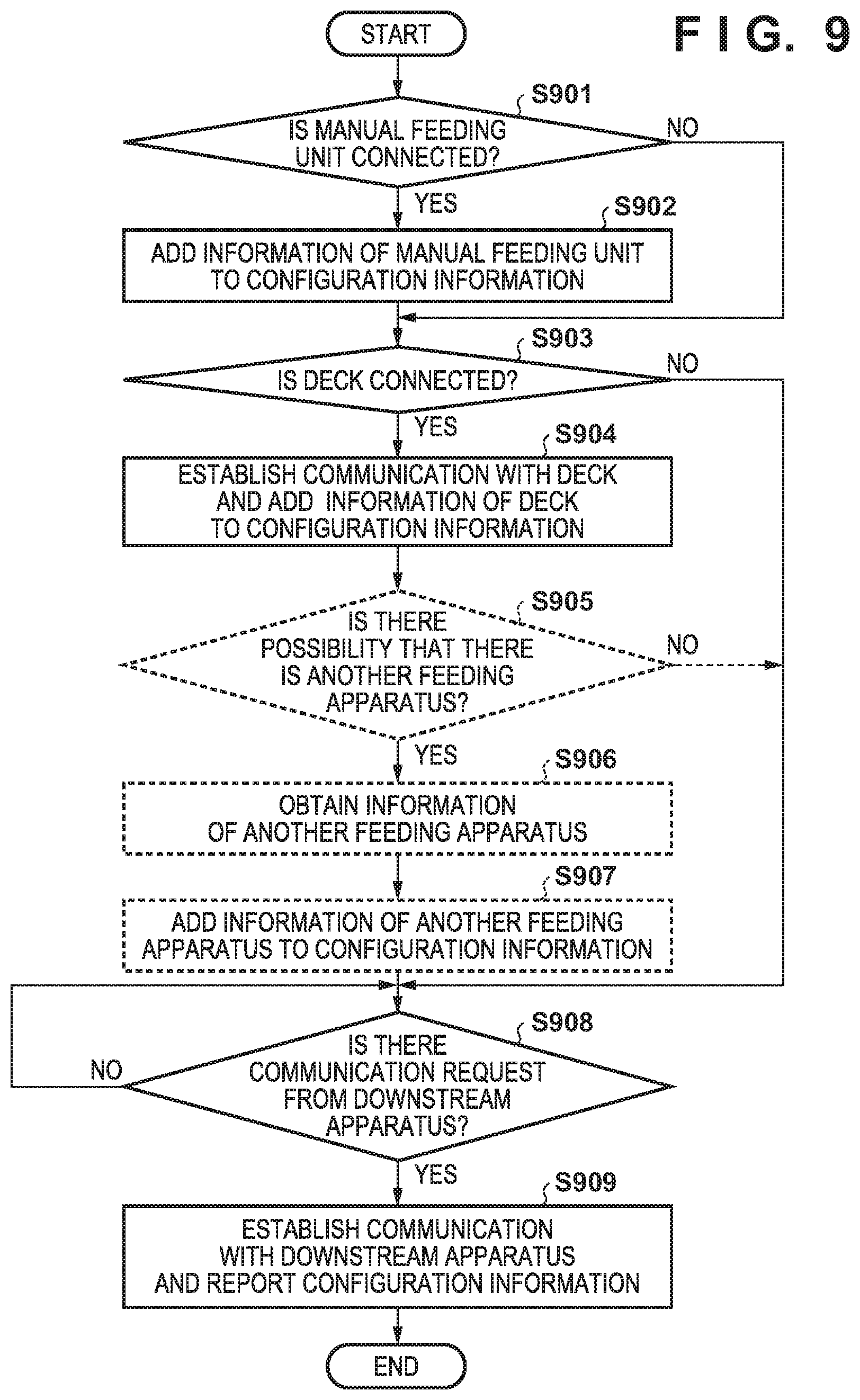
[0062] In step S901, the CPU 152b (the manual detection function portion 812b) detects whether or not the manual feeding unit 104 is connected to the feeding deck 103. A connection confirmation function portion 801b confirms whether or not the feeding apparatus is connected to the feeding decks 103a and 103b. For example, based on a switch or a sensor provided on a connecting surface 106 and the logic of the terminal, the manual detection function portion 812b may determine whether or not there is a connection of the manual feeding unit 104. This logic is decided by the ASIC 154b and outputted to the CPU 151b. For example, the logic is high when the manual feeding unit 104 is connected to the feeding deck 103, and the logic is low when the manual feeding unit 104 is not connected to the feeding deck 103. Alternatively, the manual detection function portion 812b may execute a determination based on a connection detection signal that is outputted by the manual feeding unit 104. If the manual feeding unit 104 is connected to the feeding deck 103, the CPU 151b advances the processing to step S902. If the manual feeding unit 104 is not connected to the feeding deck 103, the CPU 152b advances the processing to step S903.
[0063] In step S902, the CPU 152b (a configuration management function portion 802b) adds information illustrating that the manual feeding unit 104 is connected to the feeding deck 103 to configuration information 804b. The configuration information 804b is information for managing an existence or absence of the various feeding apparatuses configuring the feeding deck 103 and positions, and is stored in the memory 152b.
[0064] In step S903, the CPU 151b (a deck detection function portion 811b) determines whether or not decks such as the feeding deck 103 and the long sheet feeding deck 102 are connected to the connecting surface 106. For example, based on a switch or a sensor provided on the connecting surface 106 and the logic of the terminal, the deck detection function portion 811b a may determine whether or not there is a connection of the deck. Here, a deck is a feeding apparatus for which a communication establishment is necessary, such as the feeding deck 103 and the long sheet feeding deck 102. In a case where a deck is connected, the CPU 151b advances the processing to step S904. In a case where a deck is not connected, the CPU 152b finishes a connection confirmation.
[0065] In step S904, the CPU 152b (the communication control function portion 803b) establishes communication with a deck that is connected to the upstream side of the feeding deck 103, obtains configuration information of the deck, and adds the information to the configuration information 804b. Here, configuration information of the deck that is connected beside the feeding deck 103 may include specification information of that deck. The specification information may include information indicating a number of feeding stages and sheet sizes which the deck is provided with. As FIG. 1B illustrates, if the long sheet feeding deck 102 is connected to the feeding deck 103a, configuration information obtained from the long sheet feeding deck 102 includes specification information of the long sheet feeding deck 102. The presence information and specification information of the feeding apparatus present on the upstream side may be obtained by one communication, or may be obtained by a plurality of communications as follows.
[0066] In step S905, the CPU 152b (a type determination function portion 813b) determines whether or not there is a possibility that another feeding apparatus is present based on specification information obtained from the adjacent deck. The specification information includes information illustrating whether or not the adjacent deck can be connected to yet another feeding apparatus. If the deck cannot connect another feeding apparatus or is not connected to another feeding apparatus, the CPU 151b ends the connection confirmation. If there is a possibility that the deck is connected to another feeding apparatus, the CPU 151b advances the processing to step S906.
[0067] In step S906, the CPU 151b (the type determination function portion 813b) obtains this information from an adjacent deck by transmitting, to the adjacent the deck, a command to obtain information of another feeding apparatus connected to the adjacent deck.
[0068] In step S907, the CPU 152b (the configuration management function portion 802b) adds another feeding apparatus to the configuration information 804b. For example, the configuration management function portion 802b adds a connection position, specification information, or the like of another feeding apparatus to the configuration information 804b. In the case of FIG. 1C, information indicating that the manual feeding unit 104 and the long sheet feeding deck 102 are connected to the feeding deck 103b is added to the configuration information 804b. Also, specification information of the long sheet feeding deck 102 and the feeding deck 103b (for example: a number of feeding stages, a sheet size and an existence or absence of a sheet) is also added to the configuration information 804b.
[0069] In step S908, the CPU 152b (the communication control function portion 803b) determines whether or not there is a communication request from a downstream apparatus (for example: the image forming apparatus 101 or the feeding deck 103a). When the communication request is received, the CPU 151b advances the processing to step S909.
[0070] In step S909, the CPU 152b (a reporting function portion 808) transmits the configuration information 804b to the downstream apparatus. In the case of FIG. 1B, the reporting function portion 808 may transmit specification information or the like of the feeding deck 103 first, and then transmit specification information or the like of the long sheet feeding deck 102 and the manual feeding unit 104. In other words, when a query command from the image forming apparatus 101 is received, specification information of the long sheet feeding deck 102 and the manual feeding unit 104 may be transmitted.
[0071] In FIG. 10, a sheet feed control function portion 806b causes a sheet to be fed from the feeding stage that is designated by the image forming apparatus 101, and controls a conveyance of a sheet in the conveyance path. In the case of FIG. 1B, a sheet feed control function portion 806b controls feeding of the feeding stage in the feeding deck 103a and the manual feeding unit 104. An instruction transmission function portion 807b transmits designation information of the feeding stage and a feeding command to the feeding apparatus on an upstream side via the communication control function portion 803b. In the case of FIG. 1B, an instruction transmission function portion 807b transmits a feeding command to the long sheet feeding deck 102 via the communication control function portion 803b. In the case of FIG. 1C, the instruction transmission function portion 807b transmits a feeding command to the feeding deck 103b via the communication control function portion 803b.
[0072] Execution of a Job in the Image Forming Apparatus
[0073] FIG. 11 illustrates a print job executed by the CPU 151a of the image forming apparatus 101. When a print job is inputted from the operation unit 172 or a host computer, the CPU 151a executes the following processing.
[0074] In step S1101, the CPU 151a (the job execution function portion 805a) analyses the print job and determines whether or not the feeding stage designated by the print job can be directly controlled. The job execution function portion 805a obtains from the configuration information 804a information of a connection position of the designated feeding stage. Based on the obtained information, the job execution function portion 805a determines whether or not the designated feeding stage is a feeding apparatus which is connected to the image forming apparatus 101 directly or a feeding stage existing within the image forming apparatus 101. A feeding apparatus connected directly is a feeding apparatus that is attached to the mounting surface 105 (for example: the manual feeding unit 104, the long sheet feeding deck 102, and the feeding deck 103a). In other words, the CPU 151a can control these feeding apparatus directly. On the other hand, the CPU 151a cannot directly control the manual feeding unit 104 and the long sheet feeding deck 102 when they are connected to the feeding decks 103a and 103b. The configuration information 804a includes the presence or absence of a connection, a connection position, a number of feeding stages, or the like, of a feeding apparatus such as the feeding deck 103, the manual feeding unit 104, and the long sheet feeding deck 102. Therefore, the CPU 151a may determine whether or not it is possible to control the designated feeding stage directly by referring the configuration information 804a. In this way, in order to feed a sheet from the manual feeding unit 104 and the long sheet feeding deck 102 when they are connected to the feeding deck 103, it is necessary for the CPU 151a to transmit a feeding command to the feeding deck 103. Consequently, viewed from the CPU 151a, the manual feeding unit 104 and the long sheet feeding deck 102, when connected to the feeding deck 103, are feeding stages controlled indirectly. If it is possible to control the designated feeding stage directly, the CPU 151a advances the processing to step S1102. If it is not possible to control the designated feeding stage directly, the CPU 151a advances the processing to step S1103.
[0075] In step S1102, the CPU 151a (the sheet feed control function portion 806a) executes feed processing by driving the feeding roller 12 of the designated feeding stage. The CPU 151a supplies a driving signal to the manual feeding unit 104 connected to the image forming apparatus 101. Also, the CPU 151a transmits a feeding command to the long sheet feeding deck 102 and the feeding deck 103a connected to the image forming apparatus 101. In step S1103, the CPU 151a (the instruction transmission function portion 807a) transmits a feeding command accompanied by information indicating the designated feeding stage to an upstream deck (for example: the feeding deck 103a).
[0076] In step S1104, the CPU 151a (the sheet feed control function portion 806a) determines whether or not the sheet sensor 11 of the image forming apparatus 101 detects the sheet P. If the sheet P is detected, the CPU 151a advances the processing to step S1105. In step S1105, the CPU 151a (the job execution function portion 805a) controls the imaging forming unit 15 to form an image on the sheet P and discharge the sheet P from the image forming apparatus 101.
[0077] Feed Processing in the Feeding Deck
[0078] FIG. 12 illustrates feed processing executed by the CPUs 151b and 151c of the feeding deck 103. Here, too, the CPU 151b and 151c are represented by the CPU 152b collectively, and the ASIC 154b and 154c are represented by the ASIC 154b.
[0079] In step S1201, the CPU 151b (the communication control function portion 803b) determines whether or not a feeding command is received from the downstream apparatus. When a feeding command is received, the CPU 151b advances the processing to step S1202.
[0080] In step S1202, the CPU 151b (the sheet feed control function portion 806b) determines whether or not it is possible to control the feeding stage which is designated by feeding command directly. The sheet feed control function portion 806b obtains from the configuration information 804b information of a connection position of the designated feeding stage. Based on obtained information, the sheet feed control function portion 806b determines whether or not the designated feeding stage is the manual feeding unit 104 when it has been connected to the feeding deck 103 or a feeding stage present in the feeding deck 103. Note, for the long sheet feeding deck 102 and the feeding deck 103b, a feeding command must be transmitted, but the feeding apparatus can be controlled directly by the CPU 151b. The feeding deck 103a can indirectly control the manual feeding unit 104 when it is connected to the feeding deck 103b. Note that the feeding deck 103b can directly control the manual feeding unit 104 when it is connected to the feeding deck 103b. If it is possible to control the designated feeding stage directly, the CPU 151b advances the processing to step S1203. If it is not possible to control the designated feeding stage directly, the CPU 152b advances the processing to step S1204.
[0081] In step S1203, the CPU 151b (the sheet feed control function portion 806b) executes feed processing by driving the feeding roller 12 of the designated feeding stage. For example, the sheet feed control function portion 806b commands the ASIC 154b so as to drive the motor 161 of the manual feeding unit 104. The ASIC 154b drives the motor 161 of the manual feeding unit 104 in accordance with the command. Also, the feeding deck 103a transmits a feeding command received from the image forming apparatus 101 to a separate feeding deck 103b or the long sheet feeding deck 102 connected to the feeding deck 103a. In the case of FIG. 1B, the feeding deck 103a transmits the feeding command to the long sheet feeding deck 102. In the case of FIG. 1C, the feeding deck 103a transfers the feeding command to the feeding deck 103b.
[0082] In step S1204, the CPU 151b (the instruction transmission function portion 807b) transmits a feeding command accompanied by information indicating the designated feeding stage to an upstream deck. In the case of FIG. 1C, the feeding deck 103a transmits the feeding command to the feeding deck 103b. The feeding command is a command for causing the manual feeding unit 104 or the long sheet feeding deck 102 connected to the feeding deck 103b to execute feeding.
[0083] In step S1205, the CPU 151b (the sheet feed control function portion 806b) determines whether or not the sheet sensor 11 of the feeding deck 103 detects the sheet P. If the sheet P is detected, the CPU 151b advances the processing to step S1206. In step S1206, the CPU 151b (the sheet feed control function portion 806b) controls the conveyance roller 13 to discharge the sheet P to the downstream apparatus (e.g.: the image forming apparatus 101).
[0084] By virtue of the first embodiment, the cable 17 need only be connected between two adjacent devices. For this reason, it is possible for the length of the cable 17 to be short.
Second Embodiment
[0085] The image forming apparatus 101, the feeding deck 103, and the long sheet feeding deck 102 in the first embodiment can only directly communicate with apparatuses that are connected respectively adjacent thereto. On the other hand, in the second embodiment, the image forming apparatus 101 and the feeding deck 103b can communicate directly by the image forming apparatus 101 and the feeding decks 103a and 103b being bus-connected. For example, the image forming apparatus 101 is configured such that configuration information of the feeding deck 103b can be obtained without help of the feeding deck 103a. Accordingly, the image forming apparatus 101 can directly control the feeding deck 103b. However, the image forming apparatus 101 or the feeding deck 103 can still only directly control the long sheet feeding deck 102 when directly connected to the long sheet feeding deck 102. This is because the long sheet feeding deck 102 does not have a communication circuit supporting a bus connection.
[0086] [Connection Configuration]
[0087] FIG. 13 illustrates the image forming system 100 including the image forming apparatus 101, the long sheet feeding deck 102, and the manual feeding unit 104. FIG. 13 differs from FIG. 4 in that the image forming apparatus 101 has a communication I/F 155a. The communication I/F 155a may be arranged in the control unit 150a. The CPU 151a is connected to the communication I/F 155a via an I/O port 153d. The communication I/F 155a executes serial communication via a serial bus 20 arranged within the cable 17a. However, in the connection configuration that FIG. 13 illustrates, the communication I/F 155a does not execute communication because the feeding deck 103 is not connected to the image forming apparatus 101.
[0088] FIG. 14 illustrates the image forming system 100 including the image forming apparatus 101, the feeding deck 103a, the long sheet feeding deck 102, and the manual feeding unit 104. FIG. 14 differs from FIG. 5 in that the image forming apparatus 101 includes the communication I/F 155a, and the feeding deck 103a also includes a communication I/F 155b. The communication I/F 155a and the communication I/F 155b execute serial communication via the serial bus 20 arranged within the cable 17a. The communication I/F 155b may be arranged in the control unit 150b. The connection configuration is the only difference between FIG. 14 and FIG. 5, and the basic processing flow is the same as the processing flow in the connection of the first embodiment.
[0089] FIG. 15 illustrates the image forming system 100 including the image forming apparatus 101, the feeding deck 103a, the feeding deck 103b, the long sheet feeding deck 102, and the manual feeding unit 104. FIG. 15 differs from FIG. 6 in that the image forming apparatus 101 includes the communication I/F 155a, the feeding deck 103a includes the communication I/F 155b, and the feeding deck 103b includes a communication I/F 155c. The communication I/F 155b of the communication I/F 155a and the feeding deck 103a execute serial communication via the serial bus 20 arranged in the cable 17a. The communication I/F 155a and the communication I/F 155c of the feeding deck 103b execute serial communication via the serial bus 20 arranged in the cables 17a and 17c. In other words, the communication I/F 155a and the communication I/F 155c of the feeding deck 103b can communicate directly. The communication I/F 155c of the feeding deck 103b may be arranged in the control unit 150c of the feeding deck 103b.
[0090] In the connection configuration that FIG. 6 illustrates, the feeding deck 103a must transfer feeding commands addressed to the feeding deck 103b to the feeding deck 103b. However, in the connection configuration that FIG. 15 illustrates, a feeding command addressed to the feeding deck 103b is directly transmitted from the image forming apparatus 101 to the feeding deck 103b.
[0091] As is widely known, in serial communication via the serial bus 20, the master communication I/F 155a assigns a communication ID to each of the slave communication I/Fs 155b and 155c. The communication I/F 155a transmits to the serial bus a command which sets the self communication ID and the destination communication ID. Although the communication I/Fs 155b and 155c pass commands in which a communication ID assigned to self is set on to the CPUs 151b and 151c, they ignore all other commands. The communication ID of the transmission source and the communication ID of the destination are also set in a response to the command.
[0092] Processing Executed by the Control Unit of the Image Forming Apparatus
[0093] FIG. 16 illustrates a feeding apparatus connection confirmation executed by the CPU 151a of the image forming apparatus 101. Steps that have already been described are given the same reference numerals, and descriptions thereof are omitted. In a case where a deck is connected to the image forming apparatus 101 in step S703, the CPU 151a advances the processing to step S1601.
[0094] In step S1601, the CPU 151a (the connection confirmation function portion 801a) determines whether or not the feeding deck 103 is connected to the serial bus 20. The communication I/F 155a searches for another communication I/F 155b via the serial bus 20 and allocates communication IDs to the communication I/Fs 155b and 155c connected to the serial bus 20. The communication I/Fs 155b and 155c reserve each unique communication ID by transmitting a response in order from the communication I/F closest to the communication I/F 155a. The communication I/F 155a has a list of the communication I/Fs 155b and 155c for which allocation of a communication ID succeeded. This list can be referred to by the connection confirmation function portion 801a. The connection confirmation function portion 801a determines that the feeding deck 103 is not connected to the serial bus 20 if the communication I/Fs 155b and 155c are not registered in the list. The connection confirmation function portion 801a determines that the feeding deck 103 is connected to the serial bus 20 if the communication I/Fs 155b and 155c are not registered in the list. The connection confirmation function portion 801a recognizes the number of feeding decks 103 from the number of the communication I/Fs 155b and 155c registered in the list. If the feeding deck 103 is not connected to the serial bus 20, the CPU 151a advances the processing to step S704. If the feeding deck 103 is not connected to the serial bus 20, the CPU 151a advances the processing to step S1602.
[0095] In step S1602, the CPU 151a (the communication control function portion 803a) establishes communication in order with each feeding deck 103 connected to the serial bus 20, obtains configuration information of each feeding deck 103, and adds this information to the configuration information 804a.
[0096] In step S1603, the CPU 151a (the type determination function portion 813a) determines whether or not there is a possibility that another feeding apparatus is present based on specification information obtained from the feeding deck 103. Information indicating whether the feeding deck 103 can be connected to another feeding apparatus (the manual feeding unit 104 and the long sheet feeding deck 102) may be included in the specification information. If the deck cannot connect another feeding apparatus or is the feeding deck 103 when it is not connected to another feeding apparatus, the CPU 151a ends the connection confirmation. In the case of the feeding deck 103 when there is a possibility that another feeding apparatus is connected, the CPU 151a advances the processing to step S1604.
[0097] In step S1604, the CPU 151a (the type determination function portion 813a), by transmitting a command for obtaining information of other feeding apparatuses connected to the respective feeding decks 103 to the respective feeding decks 103, obtains the information from the respective feeding decks 103.
[0098] In step S1605, the CPU 151a (the configuration management function portion 802a) adds another feeding apparatus to the configuration information 804a. For example, the configuration management function portion 802a adds a connection position, specification information, or the like of another feeding apparatus to the configuration information 804a. In the case of FIG. 1B, information indicating that the manual feeding unit 104 and the long sheet feeding deck 102 are connected to the feeding deck 103a is added to the configuration information 804a. In the case of FIG. 1C, information indicating that the feeding deck 103b is connected to the feeding deck 103a and the manual feeding unit 104 and the long sheet feeding deck 102 are connected to the feeding deck 103b is added to the configuration information 804a. Also, specification information of the long sheet feeding deck 102 and the feeding deck 103b (a number of feeding stages, a sheet size and an existence or absence of a sheet) is also added to the configuration information 804a.
[0099] Processing Executed by the Control Unit of the Feeding Deck
[0100] FIG. 17 illustrates a feeding apparatus connection confirmation executed by the CPUs 151b and 151c of the feeding deck 103. Hereinafter, the CPUs 151b and 151c are collectively referred to as a CPU 151b. Steps that have already been described are given the same reference numerals, and descriptions thereof are omitted. When step S902 finishes, the CPU 151b advances the processing to step S1701.
[0101] In step S1701, the CPU 152b (the deck detection function portion 811b) determines whether or not the long sheet feeding deck 102 is connected to the connecting surface 106. In a case where the long sheet feeding deck 102 is connected, the CPU 151b advances the processing to step S1702. In a case where the long sheet feeding deck 102 is not connected, the CPU 151b advances the processing to step S1703.
[0102] In step S1702, the CPU 151b (the communication control function portion 803b) establishes communication with the long sheet feeding deck 102 via a serial line, obtains configuration information of the long sheet feeding deck 102, and adds this information to the configuration information 804b. In step S1703, the CPU 152b (the communication control function portion 803b) determines whether or not a communication request was received via the serial bus 20 from the image forming apparatus 101. If a communication request was received, the CPU 151b advances the processing to step S1704.
[0103] In step S1704, the CPU 151b (the reporting function portion 808) transmits the configuration information 804b to the image forming apparatus 101 via the serial bus 20. In the case of FIG. 1B and FIG. 1C, the reporting function portion 808 of the feeding deck 103a transmits the specification information and the like of the feeding deck 103a. In the case of FIG. 1C, the reporting function portion 808 of the feeding deck 103b initially transmits specification information and the like of the feeding deck 103b, and then may transmit specification information and the like of the long sheet feeding deck 102 or the manual feeding unit 104. In other words, when a query command from the image forming apparatus 101 is received, specification information of the long sheet feeding deck 102 and the manual feeding unit 104 may be transmitted.
[0104] Execution of a Job in the Image Forming Apparatus
[0105] The CPU 151a (the instruction transmission function portion 807a)in step S1103 of FIG. 11 transmits a feeding command to the feeding deck 103 having a designated feeding stage or to the feeding deck 103 that directly can control the designated feeding stage. For example, the instruction transmission function portion 807a refers to 804a by referring to configuration information, and identifies a feeding deck 103 having a designated feeding stage or a feeding deck 103 that directly can control the designated feeding stage. Furthermore, the instruction transmission function portion 807a transmits a feeding command to the identified feeding deck 103 via the serial bus 20. In the feeding command, information indicating the designated feeding stage is attached. Other points are as already described above.
[0106] Feed Processing in the Feeding Deck
[0107] FIG. 18 illustrates feed processing executed by the CPUs 151b and 151c of the feeding deck 103. Hereinafter, the CPUs 152b and 151c are collectively referred to as a CPU 151b. In FIG. 18, step S1202 and step S1204 illustrated in FIG. 12 do not exist. This is because a feeding command is directly transmitted to each the feeding deck 103 via the serial bus 20, and there is no transferring of the feeding command. In the case of FIG. 1C, the feeding deck 103b directly receives the feeding command from the image forming apparatus 101. The feeding deck 103b feeds a sheet from its own feeding stage 111, the long sheet feeding deck 102 or the manual feeding unit 104 in accordance with a feeding command.
[0108] By virtue of the second embodiment, the cable 17 need only be connected between an apparatus and the apparatus positioned beside it. For this reason, it is possible for the length of the cable 17 to be short.
[0109] Technical Ideas Derived From the Examples>
[0110] As illustrated in FIG. 1 or the like, the image forming system 100 having the image forming apparatus 101, and one or more feeding apparatus (for example: a feeding deck) that is connected in series to the image forming apparatus 101 and feeds the sheet P to the image forming apparatus 101 is provided. The image forming apparatus 101 has the mounting surface 105 to which one feeding apparatus among one or more feeding apparatus is connected. The mounting surface 105 is an example of a first mounting surface to which a feeding apparatus of a first type or a feeding apparatus of a second type can connect. The terminal 21a is an example of a first signal terminal that outputs a control signal from the image forming apparatus 101 to a feeding apparatus of a first type when the feeding apparatus of the first type (for example: the manual feeding unit 104), which is to be directly attached to the image forming apparatus 101, is connected to the mounting surface 105. Also, the terminal 21a is an example of a first signal terminal for outputting a control signal from the image forming apparatus to a feeding apparatus of a first type in a case where the feeding apparatus of the first type is connected to the first mounting surface. The terminal 22a is an example of a second signal terminal for communicating a signal with a feeding apparatus of a second type when the feeding apparatus of the second type (for example: the feeding deck 103) connected between the image forming apparatus 101 and a feeding apparatus of the first type is connected to the mounting surface 105. The terminal 22a is an example of a second signal terminal for communicating a signal with a feeding apparatus of the second type in a case where the feeding apparatus of the second type is connected to the first mounting surface. The inlet 18a is an example of an acceptance port that accepts the sheet P fed from one or more feeding apparatus. The inlet 18a is an example of an acceptance port that accepts the sheet P fed from a feeding apparatus of the first type or of the second type. The control unit 150a functions as a control unit (at least one first processor) for generating a control signal which is outputted to the first signal terminal or the second signal terminal.
[0111] The feeding deck 103 is an example of a feeding apparatus of the second type. The feeding deck 103 may have a second mounting surface to which a feeding apparatus of the first type can connect. The terminal 25b is an example of a third signal terminal which is to be connected to the second signal terminal via a first cable (for example: the cable 17a). The terminal 21b is an example of a fourth signal terminal which outputs a control signal to a feeding apparatus of the first type in a case where the feeding apparatus of the first type is connected to the image forming apparatus via a feeding apparatus of the second type. The terminal 21b is an example of a fourth signal terminal which outputs a control signal to a feeding apparatus of the first type in a case where the feeding apparatus of the first type is connected to the second mounting surface of a feeding apparatus of the second type.
[0112] The feeding apparatus of the first type may have a fifth signal terminal (for example: the terminal 24). The fifth signal terminal is connected to the first signal terminal of the image forming apparatus via a second cable (for example: the cable 17b) in a case where a feeding apparatus of the first type is connected to the mounting surface 105. The fifth signal terminal is connected to the fourth signal terminal (for example: the terminal 21b) of the feeding apparatus of the second type via a second cable in a case where the feeding apparatus of the first type is connected to the image forming apparatus via the feeding apparatus of the second type. In a case where the feeding apparatus of the first type is connected to the image forming apparatus via the feeding apparatus of the second type, the feeding apparatus of the first type is connected to the second mounting surface of the feeding apparatus of the second type.
[0113] The control unit 150a outputs a control signal to the feeding apparatus of the first type via the first signal terminal in a case where the feeding apparatus of the first type is connected to the mounting surface 105. The control unit 150a outputs a control command for controlling the feeding apparatus of the first type to the feeding apparatus of the second type via the second signal terminal in a case where the feeding apparatus of the first type is connected to the feeding apparatus of the second type. The feeding apparatus of the second type outputs a control signal based on a control command for controlling the feeding apparatus of the first type outputted from the image forming apparatus to the feeding apparatus of the first type via the fourth signal terminal in a case where the feeding apparatus of the first type is connected to the image forming apparatus via the feeding apparatus of the second type. In this way, in a case where the feeding apparatus of the first type is connected to the image forming apparatus via the feeding apparatus of the second type, a cable which directly connects the feeding apparatus of the first type and the image forming apparatus is not necessary, and so a cable length is shorter. Accordingly, usability in an image forming system in which a plurality of feeding apparatuses are connected is improved.
[0114] The feeding apparatus of the second type (for example: the feeding deck 103) may have a conversion unit or at least one second processor (for example: the control unit 150b) for converting a control command for controlling the feeding apparatus of the first type received from the image forming apparatus into a control signal (for example: a driving current and a driving pulse) which the feeding apparatus of the first type can receive. The conversion unit or the at least one second processor outputs the control signal from the fourth signal terminal to the feeding apparatus of the first type. Thereby, the feeding apparatus of the first type can be connected to the image forming apparatus and also the feeding apparatus of the second type.
[0115] Based on a voltage or a current or signal applied to the first signal terminal or the second signal terminal, the connection confirmation function portion 801a may function as a discrimination section (at least one first processor) that discriminates a type of a feeding apparatus connected to the mounting surface 105. In this signal, the configuration information 804b obtained from the feeding apparatus connected to the mounting surface 105 may be included. The control unit 150a may recognize whether the feeding apparatus of the first type or the feeding apparatus of the second type is connected to the mounting surface 105 based on the result of discrimination of the discrimination section. By this, the control unit 150b makes it possible to recognize the type of the feeding section connected to the upstream side.
[0116] In a case where the feeding apparatus of the second type is connected to the first mounting surface, the control unit 150a may transmit a query signal for querying whether the feeding apparatus of the first type is connected to the feeding apparatus of the second type. A query signal is transmitted to the feeding apparatus of the second type via the second signal terminal. The control unit 150a receives a response signal with respect to the query signal from the feeding apparatus of the second type. Furthermore, the control unit 150a recognizes that the feeding apparatus of the first type is connected to the second mounting surface of the feeding apparatus of the second type based on the response signal. In this way, the control unit 150b, via a feeding apparatus such as the feeding deck 103 or the like, may recognize still another feeding apparatus. By this, the control unit 150b can recognize the feeding apparatus connected to the upstream side.
[0117] The image forming apparatus 101 controls the manual feeding unit 104 or the long sheet feeding deck 102 connected to the most upstream feeding deck 103 by the feeding deck 103 connected most upstream (final position) from among a plurality of serially connected feeding decks 103. In this way, a cable through which the manual feeding unit 104 or the long sheet feeding deck 102 is directly connected to the image forming apparatus is made unnecessary by the controlling of the manual feeding unit 104 or the long sheet feeding deck 102 by the feeding deck 103 connected most upstream. Accordingly, usability in an image forming system whose plurality of feeding apparatuses is connected is corrected.
[0118] The connection confirmation function portion 801a functions as a determination section (the at least one first processor) which determines whether the feeding stage designated by the print job is the manual feeding unit or the long sheet feeding deck connected to the feeding deck connected most upstream. In a case where the feeding stage is the manual feeding unit or the long sheet feeding deck connected to the feeding deck connected most upstream, the instruction transmission function portion 807a functions as a transmission section which transmits a control command, (control signal) for controlling operation of the manual feeding unit or the long sheet feeding deck, to the feeding deck connected most upstream. Note, the control command may be conveyed or transferred via each feeding deck 103 present between the image forming apparatus and the manual feeding unit or the long sheet feeding deck. In other words, a transfer method such as in the first embodiment may be employed and a conveyance method such as in the second embodiment may be employed. By this, the image forming apparatus 101 can control the manual feeding unit or the long sheet feeding deck.
[0119] As described in the second embodiment, the image forming apparatus 101 may establish communication with each of the plurality of the feeding decks 103 serially connected. As described in the first embodiment, the image forming apparatus 101 may establish communication with the feeding deck 103a connected beside the image forming apparatus 101 from among the plurality of feeding decks. The connection confirmation function portion 801a functions as an obtainment section which obtains information (e.g.: the configuration information 804b) indicating the feeding stage of each of the plurality of feeding decks. The CPU 151a or the job execution function portion 805a may determine whether the feeding stage designated by the print job is the manual feeding unit or the long sheet feeding deck connected to the feeding deck connected most upstream based on information obtained by the obtainment section. In this way, the image forming apparatus 101 may discriminate the presence or absence of the manual feeding unit or the long sheet feeding deck by executing communication with the feeding deck 103.
[0120] The IO port 153d or the communication I/F 155a function as a first communication section connected to a communication bus for communication with the plurality of feeding decks 103. The IO port 153a functions as a second communication section which communicates with the long sheet feeding deck 102 when the long sheet feeding deck 102 is connected beside the image forming apparatus 101. The instruction transmission function portion 807a may transmit a control command for controlling the manual feeding unit or the long sheet feeding deck to the feeding deck connected most upstream via the first communication section. By this, the image forming apparatus 101 may control a manual feeding unit or a long sheet feeding deck indirectly connected to the image forming apparatus 101.
[0121] There is a case in which the manual feeding unit is connected to the feeding deck 103. In this case, the control section (at least one processor) of the feeding deck 103 control the manual feeding unit based on a control command transmitted from the image forming apparatus and received by the communication section. In a case where the manual feeding unit is connected to the image forming apparatus, the control section of the feeding deck 103 does not control the manual feeding unit.
[0122] There is a case where another feeding deck is connected downstream of the feeding deck 103 in the conveyance direction of the sheet. The control section of the feeding deck 103 receives from another feeding deck a control command for the manual feeding unit received from the image forming apparatus by another feeding deck. By this, the control section of the feeding deck 103 may control the manual feeding unit.
[0123] The connection confirmation function portion 801a may determine whether or not there is a possibility that another feeding apparatus is connected to the respective feeding decks based on information obtained from each of the plurality of feeding decks 103. Furthermore, the connection confirmation function portion 801a may query and obtain information relating to another feeding apparatus in relation to a feeding deck, from among the plurality of feeding decks, that the another feeding apparatus may be connected to. Since another feeding apparatus such as the manual feeding unit 104 or the long sheet feeding deck 102 is not directly connected to the image forming apparatus 101, it had not been possible for the image forming apparatus 101 to obtain information related to the another feeding apparatus. For this reason, the image forming apparatus 101 is configured such that information related to another feeding apparatus can be obtained by querying to the feeding deck f that another feeding apparatus may be connected to.
[0124] The feeding deck 103 is one example of a feeding apparatus connected to the upstream side of the image forming apparatus 101 in the conveyance direction of the sheet P. The IO port 153b or the communication control function portion 803b function as a communication section which communicates with the image forming apparatus 101. The feeding section (e.g.: the manual feeding unit 104 and the long sheet feeding deck 102), which is to be directly connected to the image forming apparatus 101, may be connected to the upstream side of the feeding apparatus in conveyance direction of the sheet P. In this case, the CPU 152b functions as a control section (at least one processor) which controls the feeding section based on a control command that is transmitted by the image forming apparatus 101 and received by the communication section. By this, the image forming apparatus 101 is configured such that the manual feeding unit 104 or the long sheet feeding deck 102 when connected to the feeding deck 103 can be controlled. In other words, a long cable directly connecting the image forming apparatus 101 to such feeding sections is unnecessary and a short cable through which communication between the image forming apparatus 101 and the feeding apparatus is possible may be present. Accordingly, usability is further improved.
[0125] The CPU 151b is a control section of the feeding apparatus, from among the one or more feeding apparatuses connected in series to the image forming apparatus 101, which is connected farthest from the image forming apparatus and to which the feeding section is connected. In the case of FIG. 2B, the CPU 151b of the feeding deck 103a functions as the control section. In the case of FIG. 2C, the CPU 152b of the feeding deck 103b functions as the control section. In this way, a feeding section control function is provided in the feeding deck 103 to which a feeding section such as the manual feeding unit 104 or the long sheet feeding deck 102 is connected. By this, the image forming apparatus 101 is enabled to indirectly control a feeding section such as the manual feeding unit 104 or the long sheet feeding deck 102 via the CPU 151b.
[0126] As illustrated in FIG. 2B and FIG. 2C, a feeding apparatus connected closest to the image forming apparatus from among one or a plurality of feeding apparatuses is connected directly to the image forming apparatus by a communication line (e.g.: the cable 17a). Two feeding apparatuses adjacent to the plurality of the feeding apparatuses are also directly connected by the communication line (e.g.: the cable 17b). The control command (e.g.: a feeding command) may be transferred to the feeding apparatus connected farthest from the image forming apparatus 101 via the communication line. By this, it is possible for the image forming apparatus 101 to pass a control command to the CPU 151b which controls a feeding section such as the manual feeding unit 104 or the long sheet feeding deck 102.
[0127] When the CPU 151b of the control unit 150b receives the control command for the feeding section issued by the image forming apparatus 101, the CPU 151b may determine whether or not the feeding section can be directly controlled by the control section. In a case where the feeding section can be directly controlled by the CPU 151b, the CPU 151b may control the feeding section in accordance with the control command. In a case where the feeding section cannot be directly controlled by the control section, the CPU 151b may transfer the control command to another feeding apparatus connected to the upstream side of a feeding apparatus to which the control section is provided.
[0128] The ASIC 154b may additionally have a driving circuit which drives a driving source (e.g.: the motor 161) arranged in the feeding section. By this, the feeding deck 103 may drive a feeding section such as the manual feeding unit 104 or the long sheet feeding deck 102.
[0129] The CPU 152b may detect whether or not the feeding section is connected to the feeding apparatus. When it is detected that the feeding section is connected to the feeding apparatus, the CPU 151b may report to the image forming apparatus 101 that the feeding section is connected to the feeding apparatus. By this, the image forming apparatus 101 is configured such that another feeding apparatus connected to the feeding apparatus can be recognized.
Other Embodiments
[0130] Embodiment(s) of the present invention can also be realized by a computer of a system or apparatus that reads out and executes computer executable instructions (e.g., one or more programs) recorded on a storage medium (which may also be referred to more fully as anon-transitory computer-readable storage medium') to perform the functions of one or more of the above-described embodiment(s) and/or that includes one or more circuits (e.g., application specific integrated circuit (ASIC)) for performing the functions of one or more of the above-described embodiment(s), and by a method performed by the computer of the system or apparatus by, for example, reading out and executing the computer executable instructions from the storage medium to perform the functions of one or more of the above-described embodiment(s) and/or controlling the one or more circuits to perform the functions of one or more of the above-described embodiment(s). The computer may comprise one or more processors (e.g., central processing unit (CPU), micro processing unit (MPU)) and may include a network of separate computers or separate processors to read out and execute the computer executable instructions. The computer executable instructions may be provided to the computer, for example, from a network or the storage medium. The storage medium may include, for example, one or more of a hard disk, a random-access memory (RAM), a read only memory (ROM), a storage of distributed computing systems, an optical disk (such as a compact disc (CD), digital versatile disc (DVD), or Blu-ray Disc (BD).TM.), a flash memory device, a memory card, and the like.
[0131] While the present invention has been described with reference to exemplary embodiments, it is to be understood that the invention is not limited to the disclosed exemplary embodiments. The scope of the following claims is to be accorded the broadest interpretation so as to encompass all such modifications and equivalent structures and functions.
[0132] This application claims the benefit of Japanese Patent Application No. 2019-123132, filed Jul. 1, 2019 which is hereby incorporated by reference herein in its entirety.
* * * * *
D00000
D00001
D00002
D00003
D00004
D00005
D00006
D00007
D00008
D00009
D00010
D00011
D00012

D00013
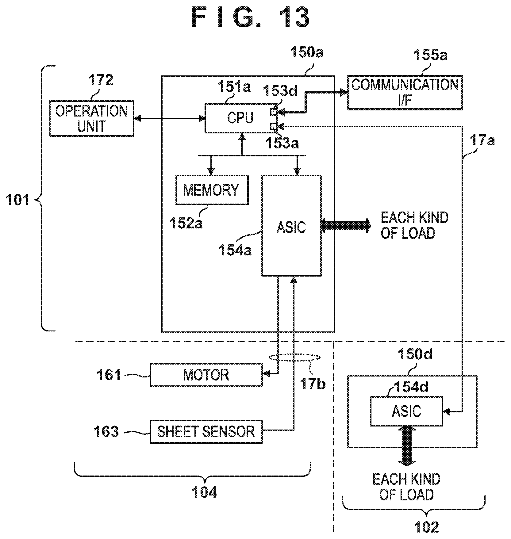
D00014
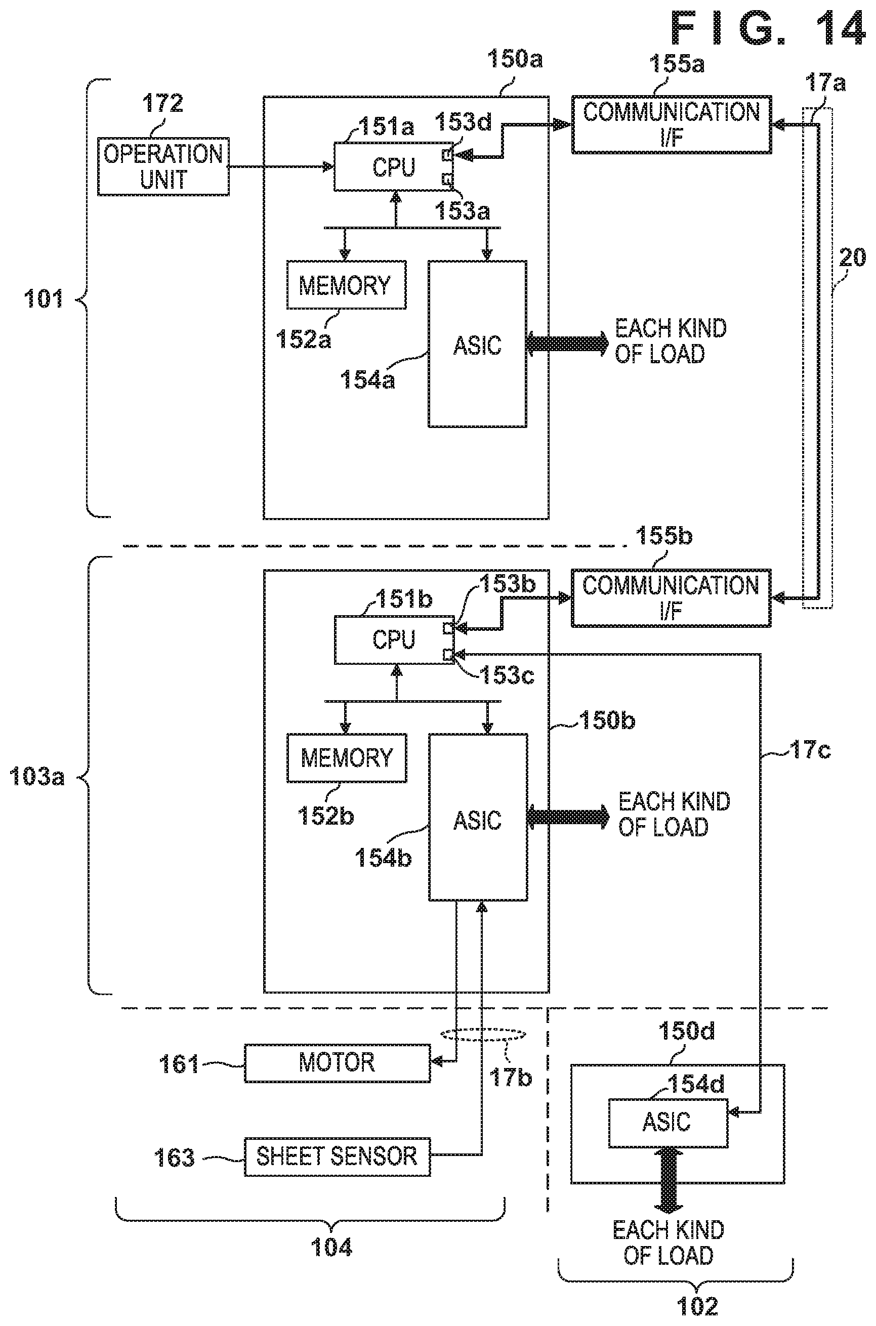
D00015
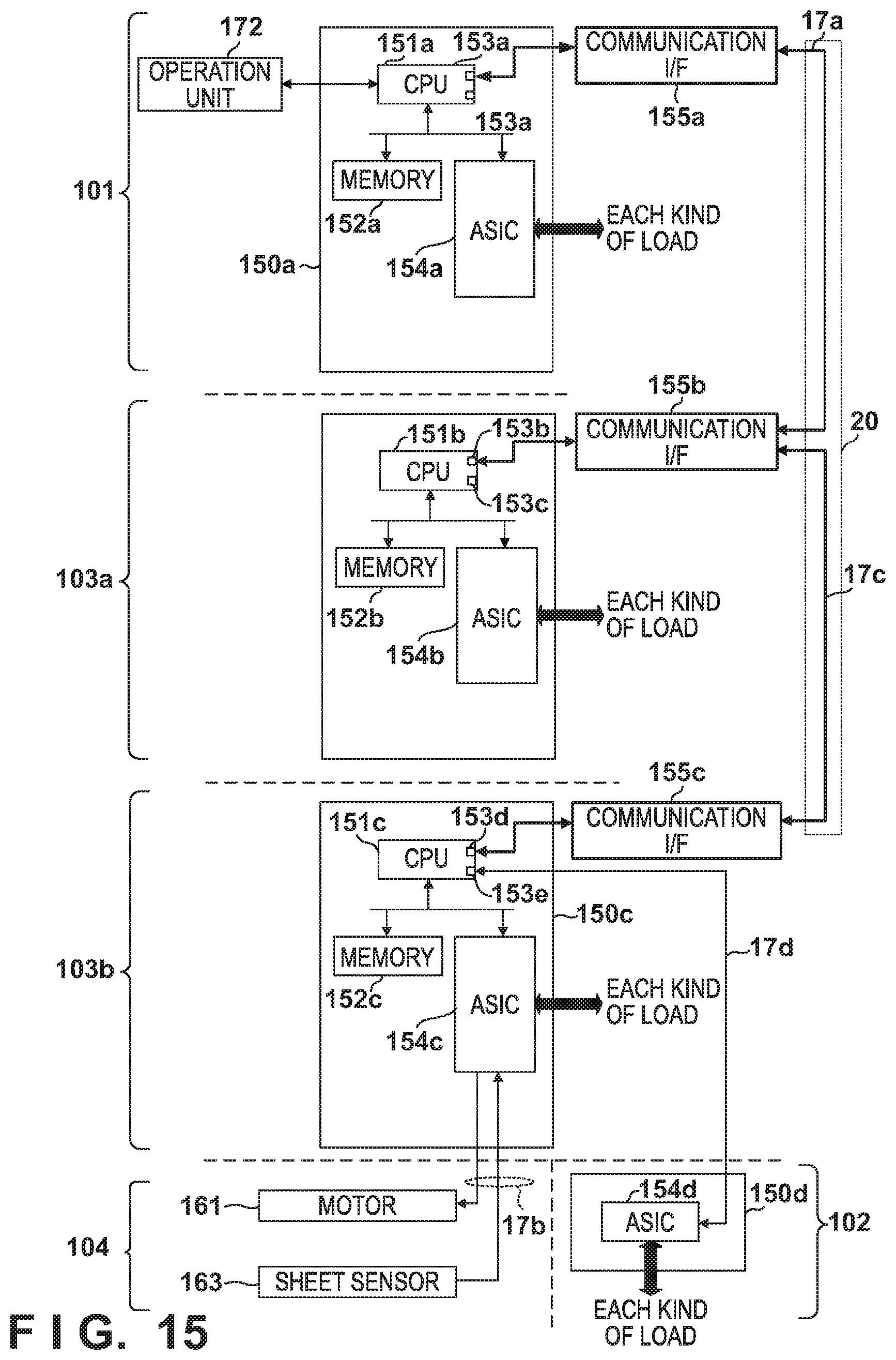
D00016

D00017

D00018

XML
uspto.report is an independent third-party trademark research tool that is not affiliated, endorsed, or sponsored by the United States Patent and Trademark Office (USPTO) or any other governmental organization. The information provided by uspto.report is based on publicly available data at the time of writing and is intended for informational purposes only.
While we strive to provide accurate and up-to-date information, we do not guarantee the accuracy, completeness, reliability, or suitability of the information displayed on this site. The use of this site is at your own risk. Any reliance you place on such information is therefore strictly at your own risk.
All official trademark data, including owner information, should be verified by visiting the official USPTO website at www.uspto.gov. This site is not intended to replace professional legal advice and should not be used as a substitute for consulting with a legal professional who is knowledgeable about trademark law.