Heat Exchanger
Nakano; Hiroyuki ; et al.
U.S. patent application number 16/977284 was filed with the patent office on 2021-01-07 for heat exchanger. This patent application is currently assigned to DAIKIN INDUSTRIES, LTD.. The applicant listed for this patent is DAIKIN INDUSTRIES, LTD.. Invention is credited to Tooru Andou, Hideyuki Kusaka, Hiroyuki Nakano, Shun Yoshioka.
| Application Number | 20210003350 16/977284 |
| Document ID | / |
| Family ID | |
| Filed Date | 2021-01-07 |


View All Diagrams
| United States Patent Application | 20210003350 |
| Kind Code | A1 |
| Nakano; Hiroyuki ; et al. | January 7, 2021 |
HEAT EXCHANGER
Abstract
A heat exchanger includes: heat transfer units that each comprise heat transfer channel portions and auxiliary heat transfer portions. The heat transfer channel portions and the auxiliary heat transfer portions extend in a first direction and are disposed in a second direction that intersects with or is perpendicular to the first direction. The heat transfer units are disposed in a third direction that is different from both of the first direction and the second direction. The heat transfer units each has an airflow-upstream region and an airflow-downstream region in the second direction. When the heat exchanger is used as an evaporator, the heat exchanger causes a refrigerant to flow into a heat transfer channel portion disposed in the airflow-upstream region, and then causes the refrigerant to flow out to a heat transfer channel portion disposed in the airflow-downstream region.
| Inventors: | Nakano; Hiroyuki; (Osaka-shi, Osaka, JP) ; Andou; Tooru; (Osaka-shi, Osaka, JP) ; Kusaka; Hideyuki; (Osaka-shi, Osaka, JP) ; Yoshioka; Shun; (Osaka-shi, Osaka, JP) | ||||||||||
| Applicant: |
|
||||||||||
|---|---|---|---|---|---|---|---|---|---|---|---|
| Assignee: | DAIKIN INDUSTRIES, LTD. Osaka JP |
||||||||||
| Appl. No.: | 16/977284 | ||||||||||
| Filed: | February 22, 2019 | ||||||||||
| PCT Filed: | February 22, 2019 | ||||||||||
| PCT NO: | PCT/JP2019/006840 | ||||||||||
| 371 Date: | September 1, 2020 |
| Current U.S. Class: | 1/1 |
| International Class: | F28F 1/26 20060101 F28F001/26 |
Foreign Application Data
| Date | Code | Application Number |
|---|---|---|
| Mar 1, 2018 | JP | 2018-036981 |
Claims
1-9. (canceled)
10. A heat exchanger comprising: heat transfer units that each comprise heat transfer channel portions and auxiliary heat transfer portions, wherein the heat transfer channel portions and the auxiliary heat transfer portions extend in a first direction and are disposed in a second direction that intersects with or is perpendicular to the first direction, the heat transfer units are disposed in a third direction that is different from both of the first direction and the second direction, the heat transfer units each has an airflow-upstream region and an airflow-downstream region in the second direction, and when the heat exchanger is used as an evaporator, the heat exchanger causes a refrigerant to flow into a heat transfer channel portion disposed in the airflow-upstream region, and then causes the refrigerant to flow out to a heat transfer channel portion disposed in the airflow-downstream region.
11. The heat exchanger according to claim 1, wherein a number of heat transfer channel portions disposed in the airflow-downstream region is larger than a number of heat transfer channel portions disposed in the airflow-upstream region.
12. The heat exchanger according to claim 10, further comprising: a decompressing mechanism that decompresses the refrigerant, wherein the heat exchanger causes the refrigerant to flow from the heat transfer channel portion disposed in the airflow-upstream region into the heat transfer channel portion disposed in the airflow-downstream region via the decompressing mechanism.
13. The heat exchanger according to claim 10, further comprising: an upper header connected to the heat transfer units from above in the first direction; and a lower header connected to the heat transfer units from below in the first direction, wherein the upper header and the lower header form a part of a channel of the refrigerant.
14. The heat exchanger according to claim 13, wherein the airflow-upstream region and the airflow-downstream region are separated by a partition disposed inside of at least one of the upper header or the lower header.
15. The heat exchanger according to claim 10, wherein each of the heat transfer units comprises eight or more heat transfer channel portions, and at least two or more of the heat transfer channel portions are disposed in the airflow-upstream region.
16. The heat exchanger according to claim 10, wherein, when viewed from the first direction, a heat insulator is applied to an end portion of each of the heat transfer units in the second direction.
17. The heat exchanger according to claim 7, wherein in each of the heat transfer units, one of the auxiliary heat transfer portions is at an end of the respective heat transfer units in the second direction when viewed from the first direction, and the one of the auxiliary heat transfer portion in each of the heat transfer units has a closed shape.
18. An air conditioner comprising the heat exchanger according to claim 10.
Description
TECHNICAL FIELD
[0001] The present invention relates to a heat exchanger.
BACKGROUND
[0002] Conventional heat exchangers used in an air conditioner or the like include a small-diameter heat transfer tube unit that is formed by stacking heat transfer fin plates (see, for example, Patent Literature 1 (Japanese Unexamined Patent Application Publication No. 2006-90636) and the like).
[0003] When a heat exchanger is used as an evaporator in a low temperature environment, frosting may concentratedly occur in a part of the heat exchanger due to internal heat flux distribution. Then, blockage of an air passage may occur in the part where frosting has concentratedly occurred, and the performance of the heat exchanger may decrease.
SUMMARY
[0004] A heat exchanger according to a first aspect includes a plurality of heat transfer units in each of which a plurality of heat transfer channel portions and a plurality of auxiliary heat transfer portions, each of which extends in a first direction, are formed so as to be arranged in a second direction that intersects with or is perpendicular to the first direction, the heat transfer units being arranged in a third direction that is different from both of the first direction and the second direction.
[0005] In the heat exchanger according to the first aspect, the heat transfer units are each divided into an airflow-upstream region and an airflow-downstream region in the second direction. When used as an evaporator, the heat exchanger according to the first aspect causes a refrigerant to flow into a heat transfer channel portion disposed in the airflow-upstream region, and then causes the refrigerant to flow out to a heat transfer channel portion disposed in the airflow-downstream region. Such a configuration can optimize the heat exchange performance of the entirety of the heat exchanger.
[0006] A heat exchanger according to a second aspect is the heat exchanger according to the first aspect, in which the number of heat transfer channel portions disposed in the airflow-downstream region is larger than the number of heat transfer channel portions disposed in the airflow-upstream region. Such a configuration can realize optimal heat exchange while suppressing frosting.
[0007] A heat exchanger according to a third aspect is the heat exchanger according to the first or second aspect, further including a decompressing mechanism that decompresses the refrigerant. The heat exchanger according to the third aspect causes the refrigerant to flow from the heat transfer channel portion disposed in the airflow-upstream region into the heat transfer channel portion disposed in the airflow-downstream region via the decompressing mechanism. Such a configuration can further suppress frosting.
[0008] A heat exchanger according to a fourth aspect is the heat exchanger according to any one of the first to third aspects, further including an upper header and a lower header that are connected to the heat transfer units from above and below in the first direction and that form a part of a channel of the refrigerant. Such a configuration can realize a heat exchanger that can easily discharge dew condensation water.
[0009] A heat exchanger according to a fifth aspect is the heat exchanger according to the fourth aspect, in which the airflow-upstream region and the airflow-downstream region are formed by a partition member (i.e., partition) disposed inside of the upper header and/or the lower header. Accordingly, the airflow-upstream region and the airflow-downstream region can be easily formed.
[0010] A heat exchanger according to a sixth aspect is the heat exchanger according to any one of the first to fifth aspects, in which each of the heat transfer units includes at least eight or more heat transfer channel portions, and at least two or more of the heat transfer channel portions are disposed in the airflow-upstream region. Such a configuration can optimize heat exchange performance.
[0011] A heat exchanger according to a seventh aspect is the heat exchanger according to any one of the first to sixth aspects, in which, when seen in the first direction, a heat insulator is applied to an end portion of each of the heat transfer units in the second direction. Accordingly, decrease of temperature at the end portion can be suppressed.
[0012] A heat exchanger according to an eighth aspect is the heat exchanger according to the seventh aspect, in which, in each of the heat transfer units, a first auxiliary heat transfer portion that is one of the auxiliary heat transfer portions is formed at an end portion in the second direction when seen in the first direction. The first auxiliary heat transfer portion has a closed shape. Thus, water drainage performance during a defrosting operation can be increased.
[0013] An air conditioner according to a ninth aspect includes the heat exchanger according to any one of the first to eighth aspects.
BRIEF DESCRIPTION OF THE DRAWINGS
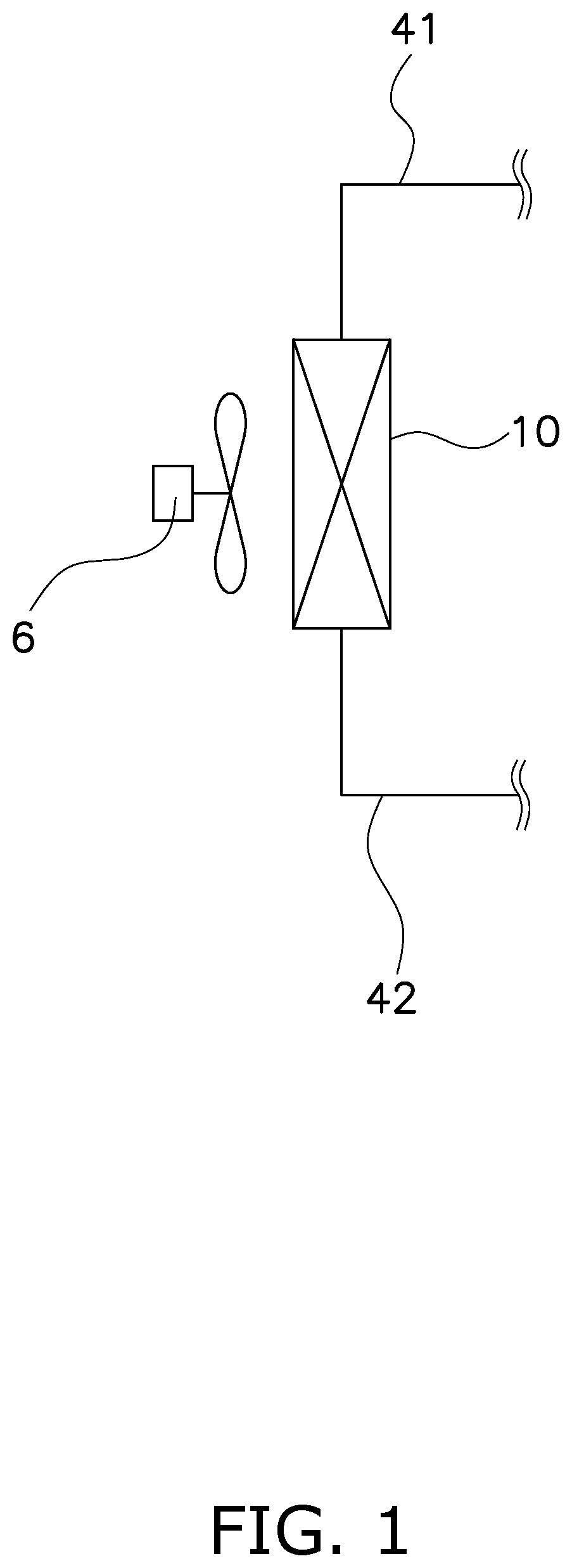
[0014] FIG. 1 is a schematic view illustrating the concept of a heat exchanger 10 according to one or more embodiments.
[0015] FIG. 2 is a schematic view illustrating the configuration of the heat exchanger 10 according to one or more embodiments.
[0016] FIG. 3 is a schematic view illustrating the cross-sectional shape of a first header 21 according to one or more embodiments.
[0017] FIG. 4 is a schematic view illustrating the cross-sectional shape of a second header 22 according to one or more embodiments.
[0018] FIG. 5 is a schematic view illustrating the configuration of a heat transfer unit 30 according to one or more embodiments.
[0019] FIG. 6 is a schematic view for describing the configuration of the heat transfer unit 30 according to one or more embodiments.
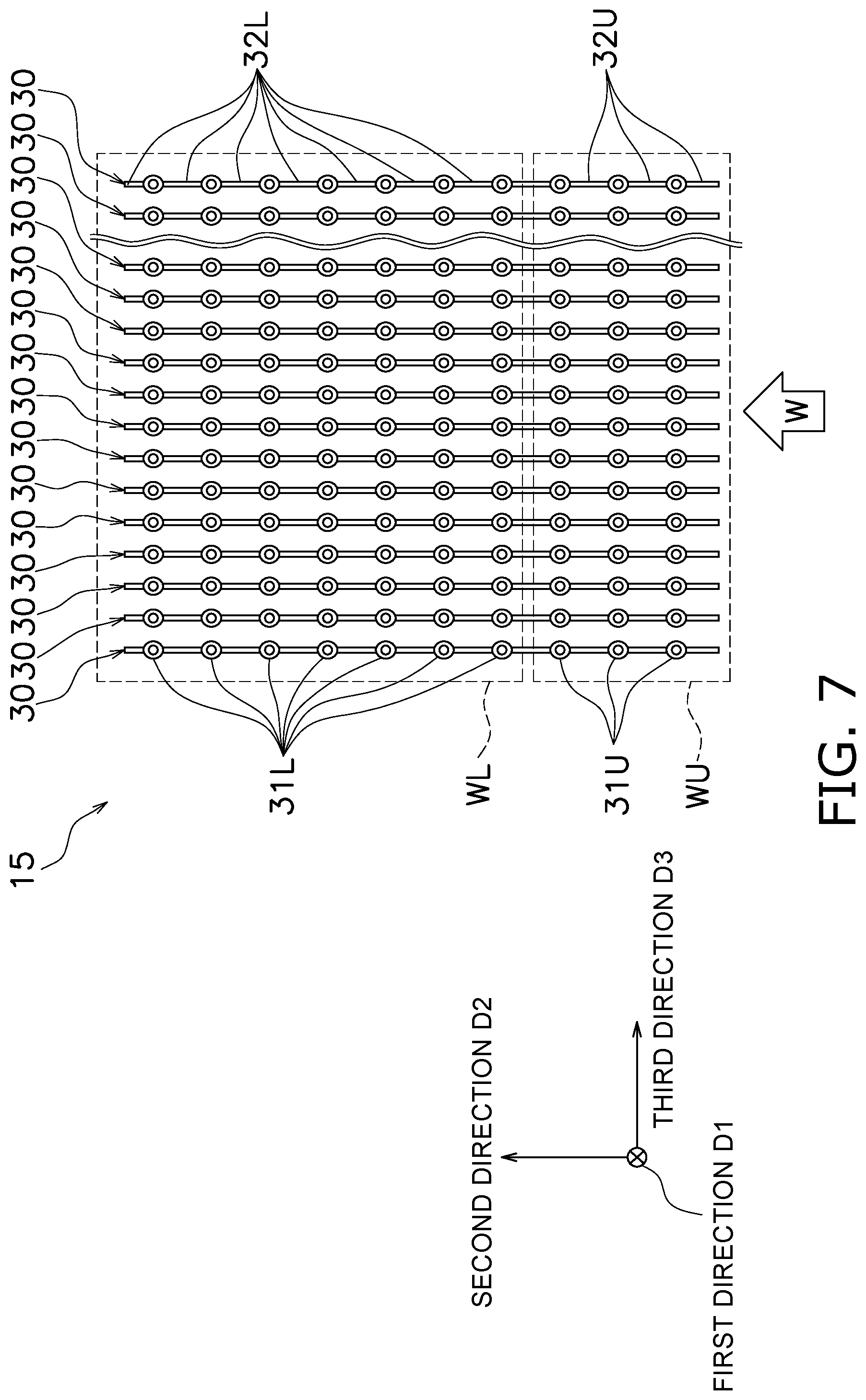
[0020] FIG. 7 is a schematic view for describing the configuration of a heat transfer unit group 15 according to one or more embodiments.
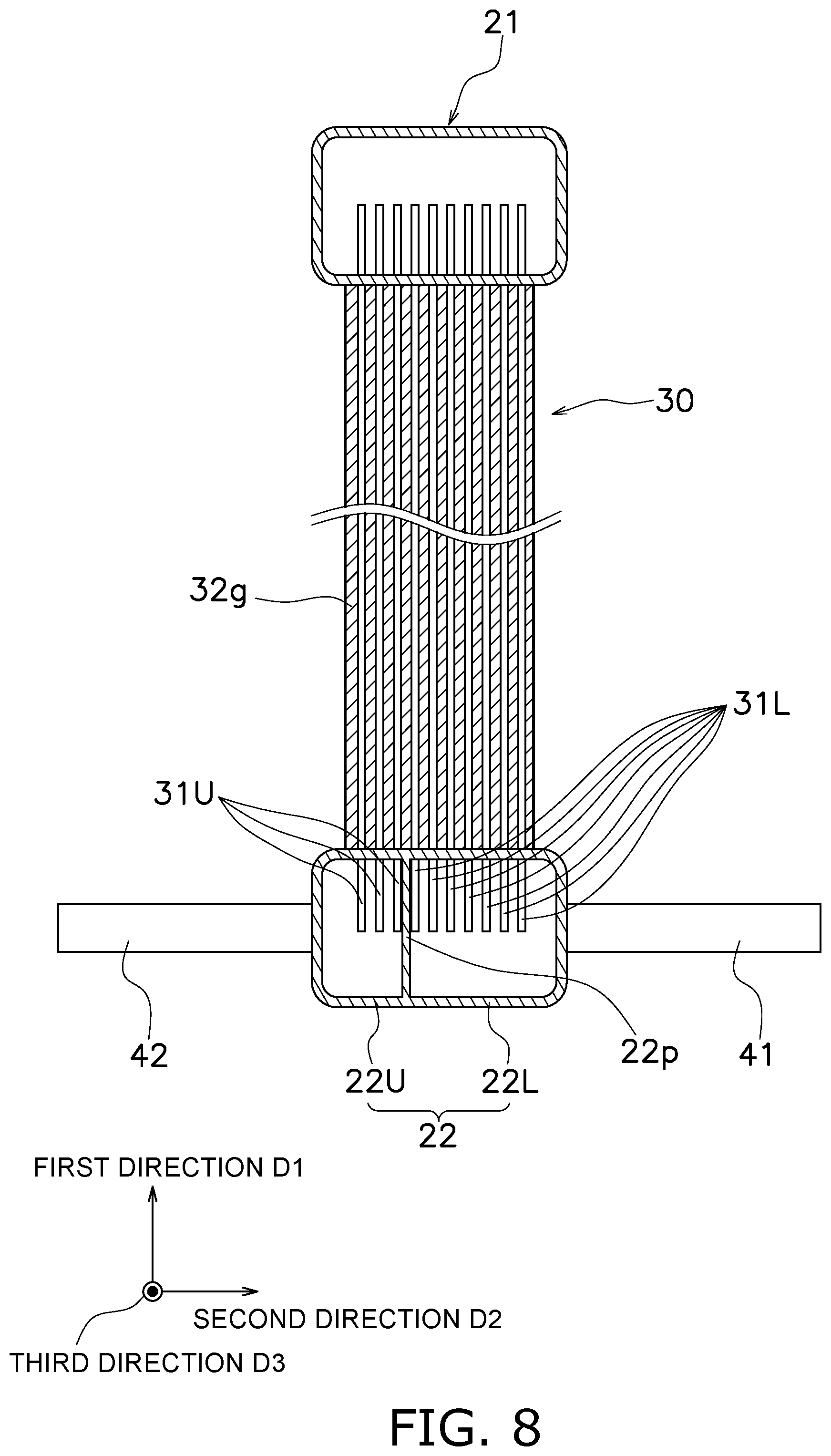
[0021] FIG. 8 is a schematic view illustrating the cross-sectional shape of the heat exchanger 10 according to one or more embodiments.
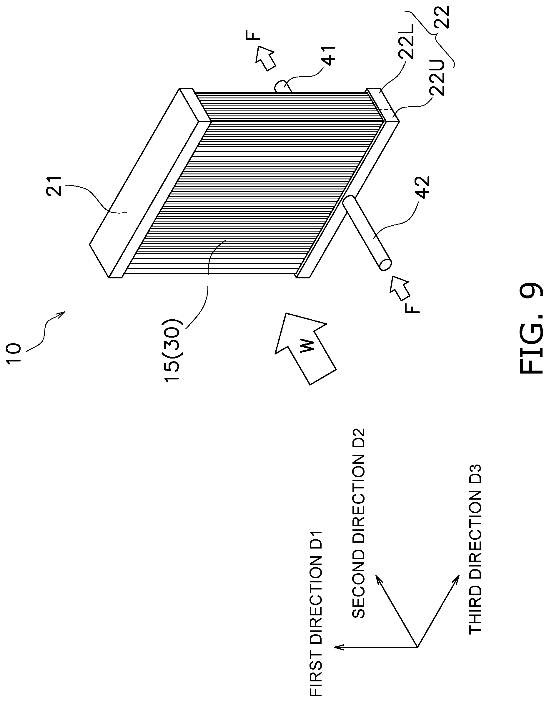
[0022] FIG. 9 is a view for describing a refrigerant channel of the heat exchanger 10 according to one or more embodiments.
[0023] FIG. 10 is a view for describing the refrigerant channel of the heat exchanger 10 according to one or more embodiments.
[0024] FIG. 11 is a schematic view illustrating the configuration of a heat exchanger 10Z for comparison.
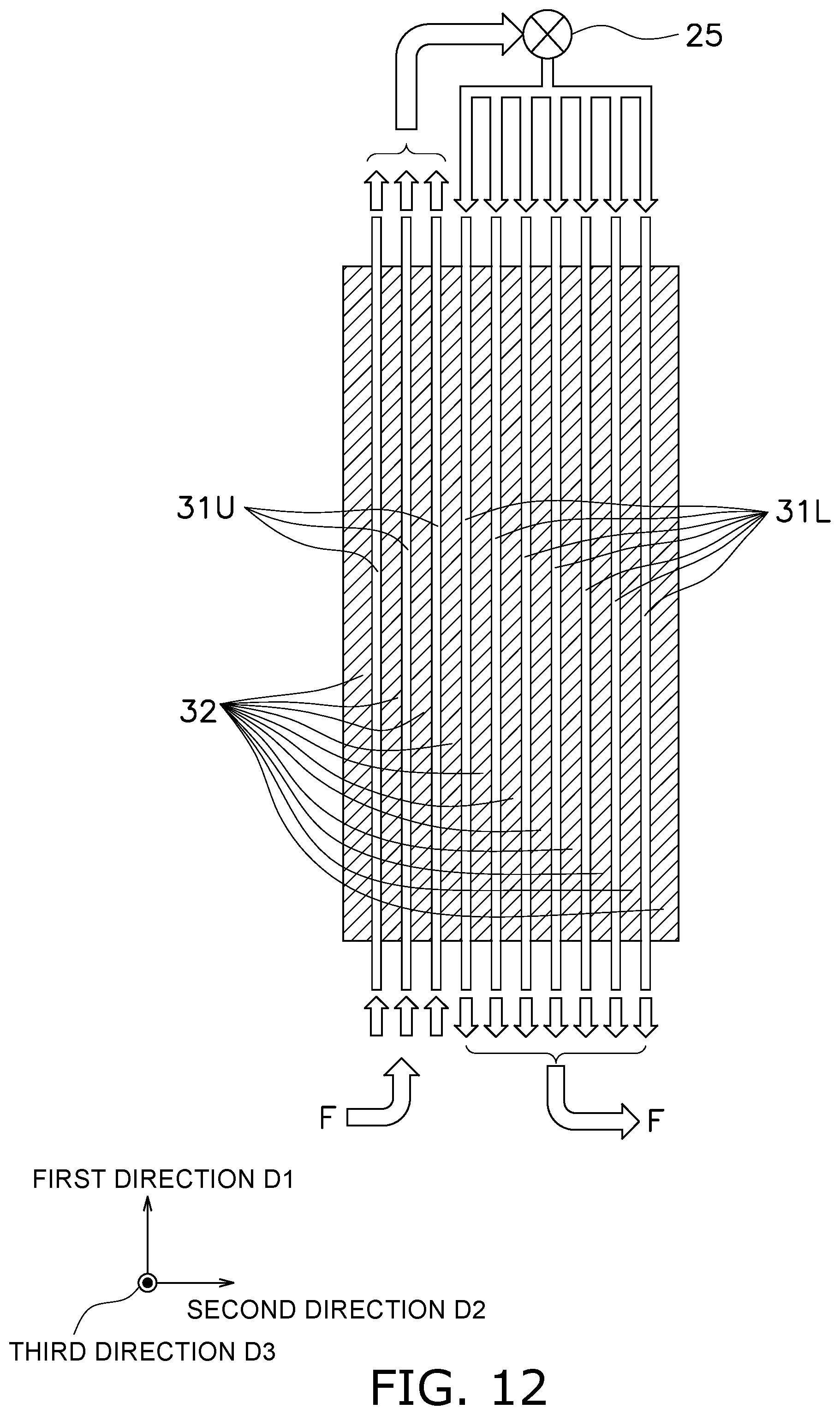
[0025] FIG. 12 is a view for describing a refrigerant channel of a heat exchanger 10 according to a modification A.
[0026] FIG. 13 is a view for describing a refrigerant channel of a heat exchanger 10Y according to a modification B.
[0027] FIG. 14 is a schematic view for describing the configuration of a heat transfer unit group 15 according to a modification C.
[0028] FIG. 15 is a schematic view for describing the configuration of the heat transfer unit group 15 according to a modification C.
[0029] FIG. 16 is a schematic view for describing the configuration of a heat transfer unit group 15 according to a modification E.
[0030] FIG. 17 is a schematic view for describing the configuration of the heat transfer unit group 15 according to the modification E (partial enlarged view of FIG. 16).
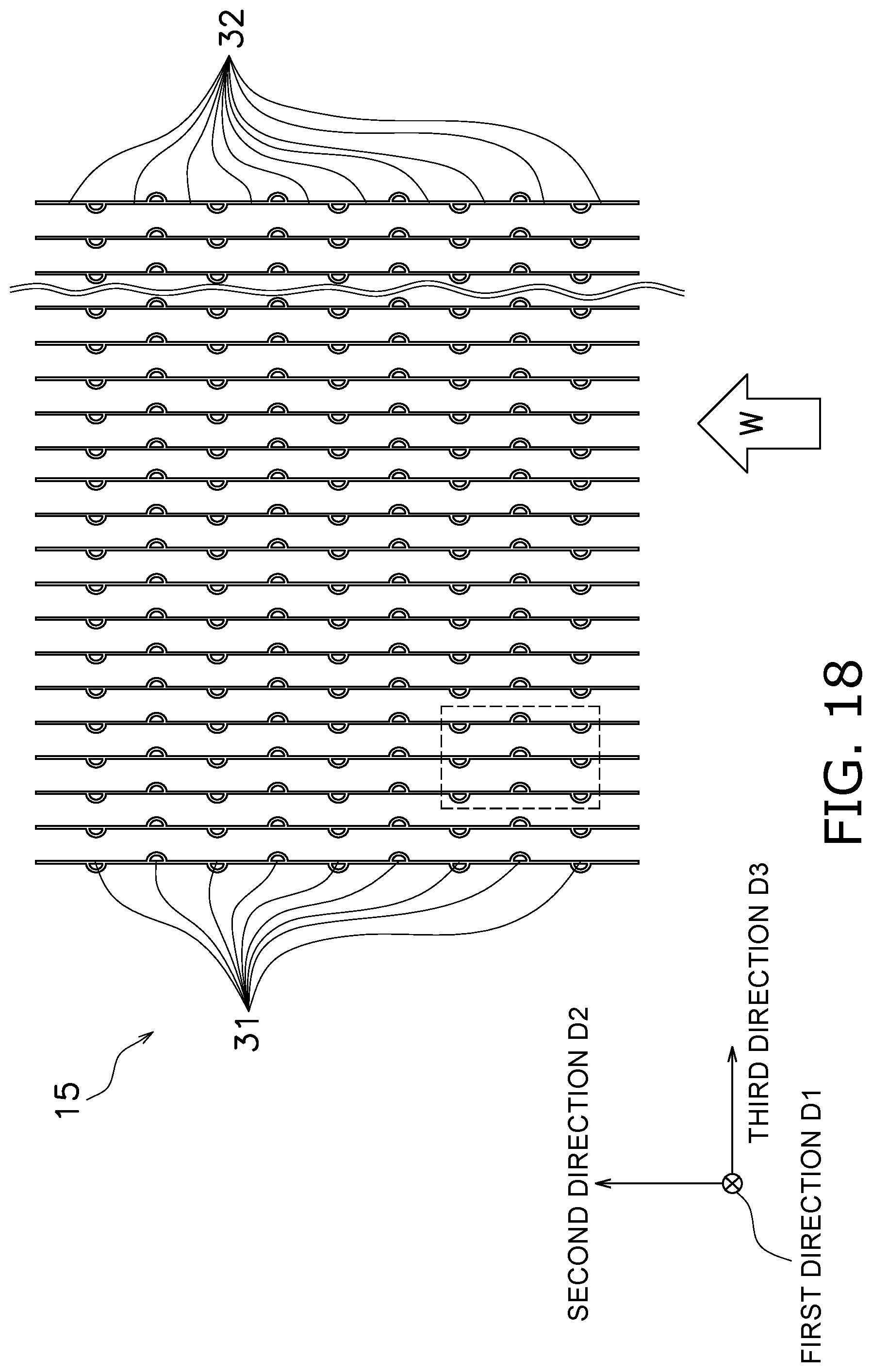
[0031] FIG. 18 is a schematic view for describing the configuration of a heat transfer unit group 15 according to a modification F.
[0032] FIG. 19 is a schematic view for describing the configuration of the heat transfer unit group 15 according to the modification F (partial enlarged view of FIG. 18).
[0033] FIG. 20 is a schematic view for describing a heat transfer unit group 15 according to a modification G.
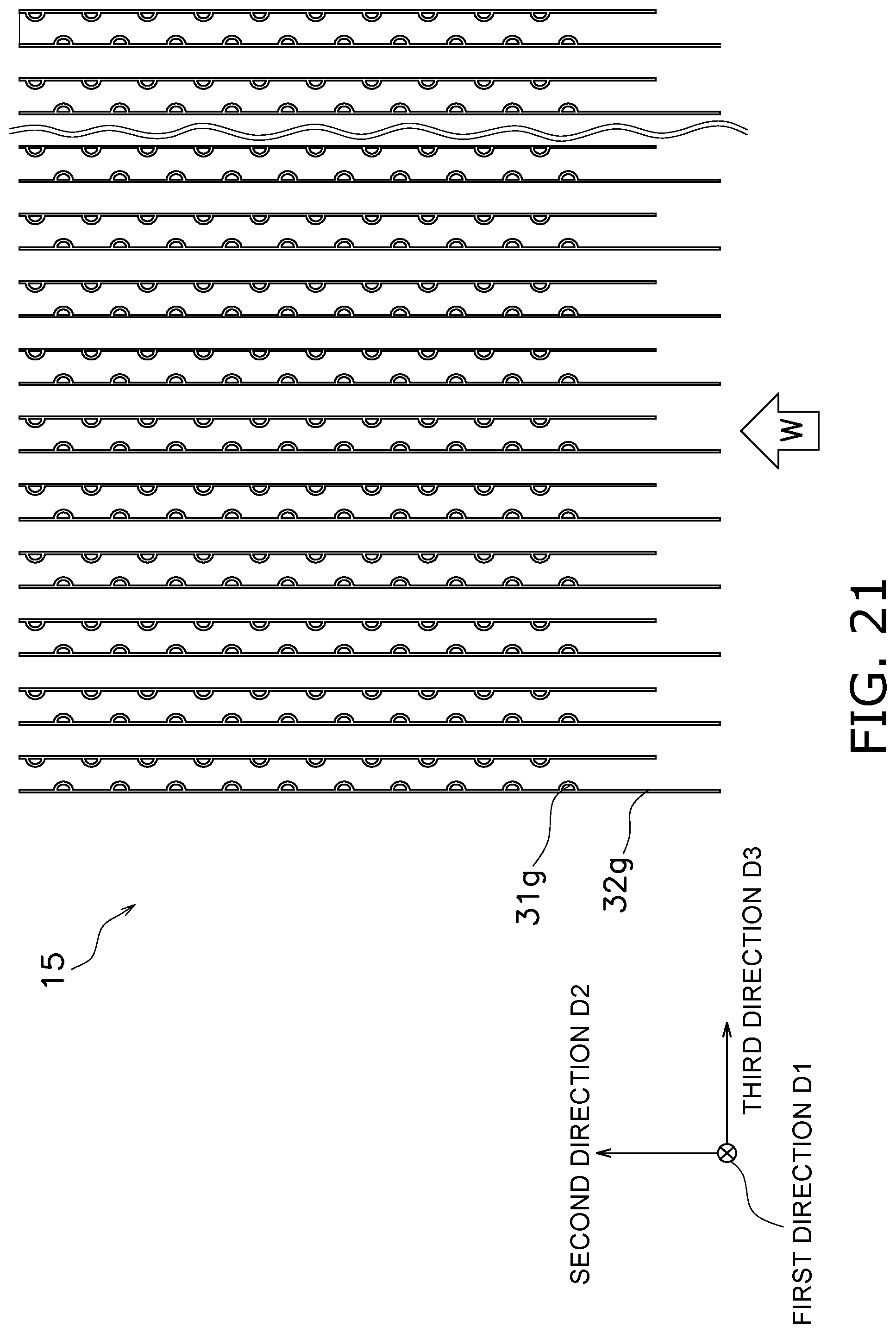
[0034] FIG. 21 is a schematic view for describing the heat transfer unit group 15 according to the modification G.
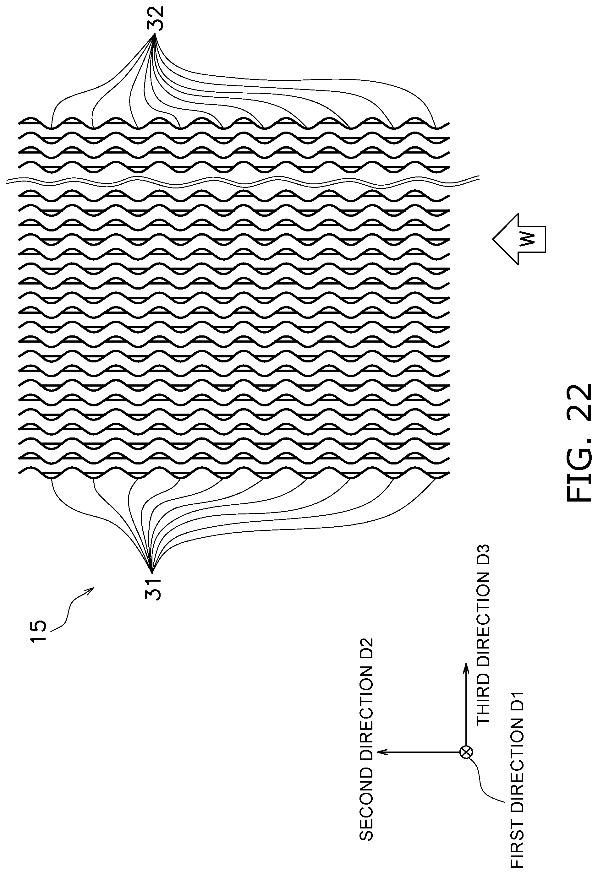
[0035] FIG. 22 is a schematic view for describing the configuration of a heat transfer unit group 15 according to a modification H.
DETAILED DESCRIPTION
[0036] (1) Overview of Heat Exchanger
[0037] A heat exchanger 10 performs heat exchange between a fluid that flows inside and air that flows outside. To be specific, as conceptually illustrated in FIG. 1, a first pipe 41 and a second pipe 42, through which a refrigerant flows into or out from the heat exchanger 10, are attached to the heat exchanger 10. A fan 6, for sending air to the heat exchanger 10, is disposed near the heat exchanger 10. The fan 6 generates airflow toward the heat exchanger 10, and, when the airflow passes through the heat exchanger 10, heat exchange is performed between the heat exchanger 10 and air. The heat exchanger 10 functions as an evaporator that absorbs heat from air and as a condenser (radiator) that releases heat to air, and can be installed in an air conditioner or the like.
[0038] (2) Details of Heat Exchanger
[0039] (2-1) Overall Configuration
[0040] As illustrated in FIG. 2, the heat exchanger 10 includes a heat transfer unit group 15, a first header 21, and a second header 22.
[0041] The heat transfer unit group 15 includes a plurality of heat transfer units 30. The heat transfer unit group 15 is disposed so that airflow generated by the fan 6 passes through spaces between the heat transfer units 30. Details of the arrangement of these members will be described below.
[0042] (2-2) Header
[0043] As illustrated in FIG. 3, the first header 21 is a hollow member that is configured so that a refrigerant in a gas phase, a liquid phase, and a gas-liquid two-phase can flow through the inside thereof. The first header 21 is connected to the heat transfer units 30 at a position above the heat transfer units 30. A connection surface 21S, to which the heat transfer units 30 are connected, is formed on the lower side of the first header 21. Coupling holes, into which end portions 31e of heat transfer channel portions 31 (described below) are inserted, are formed in the connection surface 21S. FIG. 3 illustrates a cross section of the first header 21 when seen in a third direction D3. The definition of the third direction D3 will be described below.
[0044] The second header 22 is connected to the first pipe 41, the second pipe 42, and the heat transfer unit 30 at a position below the heat transfer units 30; and allows a refrigerant to flow into and flow out of the first pipe 41, the second pipe 42, and the heat transfer units 30. As with the first header 21, the second header 22 is a hollow member that is configured so that a refrigerant in a gas phase, a liquid phase, and a gas-liquid two-phase can flow through the inside thereof. As illustrated in FIG. 4, the second header 22 has a partition member 22p that extends in the third direction D3 and partitions the inside of the second header 22. In the example shown in FIG. 4, for convenience of description, it is assumed that the second header 22 is partitioned by the partition member 22p into an airflow-upstream second header 22U and an airflow-downstream second header 22L. The airflow-upstream second header 22U and the airflow-downstream second header 22L are respectively connected to the second header 22 and the first header 21. The partition member 22p may be integrally formed with the second header 22 or may be formed as an independent object. A connection surface 22S, to which the heat transfer units 30 are connected, is formed on the upper side of the second header 22. Coupling holes, into which end portions 31e of heat transfer channel portions 31 (described below) are inserted, are formed in the connection surface 22S. FIG. 4 illustrates the cross-sectional shape of the second header 22 when seen in a third direction D3. The definition of the third direction D3 will be described below.
[0045] (2-3) Heat Transfer Unit
[0046] (2-3-1)
[0047] As illustrated in FIG. 5, in the heat transfer unit 30, a plurality of heat transfer channel portions 31 and a plurality of auxiliary heat transfer portions 32, each of which extends in a "first direction D1", are formed so as to be arranged in a "second direction D2" that intersects with or is perpendicular to the first direction D1. Here, the heat transfer channel portions 31 each have a substantially cylindrical shape, and the auxiliary heat transfer portions 32 each have a substantially flat plate-like shape. As illustrated in FIG. 6, the heat transfer channel portions 31 are formed so as to be aligned in the second direction D2 at a predetermined pitch PP. The heat transfer unit group 15 illustrated in FIG. 7 is formed by arranging such heat transfer units 30 in a "third direction D3" that is different from both of the first direction D1 and the second direction D2. Here, the heat transfer unit group 15 includes at least three or more heat transfer units 30 that are arranged in a stacked manner.
[0048] For convenience of description, it is assumed that the first direction D1, the second direction D2, and the third direction D3 are perpendicular to each other. However, these directions D1 to D3 need not be completely perpendicular to each other, and it is possible to realize the heat exchanger 10 according to the present embodiment as long as these directions intersect with each other.
[0049] The heat transfer units 30 are connected to the first header 21 and the second header 22 at the connection surfaces 21S and 22S of the first header 21 and the second header 22. To be specific, as illustrated in FIG. 5, at end portions of the heat transfer units 30 in the first direction D1, end portions 31e of the heat transfer channel portions 31 protrude from end portions 32e of the auxiliary heat transfer portions 32. The end portions 31e of the heat transfer channel portions 31 are inserted into the coupling holes formed in the connection surfaces 21S and 22S of the first header 21 and the second header 22. The heat transfer units 30 are fixed in place between the first header 21 and the second header 22 by, for example, brazing the connection portions (see FIG. 8).
[0050] The heat transfer channel portion 31 enables a refrigerant to move between the first header 21 and the second header 22. To be specific, a substantially cylindrical passage is formed in the heat transfer channel portion 31, and the refrigerant moves in the passage. The heat transfer channel portion 31 according to the present embodiment has a linear shape in the first direction D1.
[0051] The auxiliary heat transfer portion 32 accelerates heat exchange between a refrigerant that flows in adjacent heat transfer channel portions 31 and ambient air. Here, as with the heat transfer channel portion 31, the auxiliary heat transfer portion 32 is formed so as to extend in the first direction D1 and is disposed so as to be in contact with the adjacent heat transfer channel portions 31. The auxiliary heat transfer portion 32 may be integrally formed with or may be independently formed from the heat transfer channel portions 31.
[0052] (2-3-2)
[0053] At least eight or more heat transfer channel portions 31 are formed in the heat transfer unit 30 according to the present embodiment. At least two or more of the heat transfer channel portions 31 are disposed in an airflow-upstream region.
[0054] FIG. 8 illustrates an example of such a configuration. Here, ten heat transfer channel portions 31 are formed in one heat transfer unit 30. The inside of the second header 22 is partitioned by the partition member 22p into the airflow-upstream second header 22U, which is disposed in an airflow-upstream region WU, and the airflow-downstream second header 22L, which is disposed in an airflow-downstream region WL. Three heat transfer channel portions 31U are connected to the airflow-upstream second header 22U, and seven heat transfer channel portions 31L are connected to the airflow-downstream second header 22L. An auxiliary heat transfer portion 32g is formed at an end portion on the most airflow-upstream side of the heat transfer unit 30. FIG. 8 is a schematic view illustrating the cross-sectional shape of the heat exchanger 10 when seen in the third direction D3.
[0055] (2-4) Refrigerant Channel
[0056] When the heat exchanger 10 is used as an evaporator, airflow W that is generated by the fan 6 flows in the second direction D2 as illustrated in FIG. 9. In this state, a refrigerant F in a liquid phase flows into the heat exchanger 10 from the second pipe 42. Next, the refrigerant F flows into the airflow-upstream second header 22U from the second pipe 42. Then, as illustrated in FIG. 10, the refrigerant F flows from a lower position to an upper position via the heat transfer channel portions 31U, which are connected to the airflow-upstream second header 22U. Next, the refrigerant F flows into the airflow-downstream second header 22L via the heat transfer channel portions 31L, which are connected to the first header 21 and the airflow-downstream second header 22L. While the refrigerant F flows through the heat transfer channel portions 31U and 31L, the refrigerant F exchanges heat with the airflow W. Thus, the refrigerant F evaporates and changes into a gas phase. Then, the refrigerant F in the gas phase flows out from the first pipe 41. FIG. 10 illustrates a state when the heat transfer unit 30 is seen in a third direction D3.
[0057] When the heat exchanger 10 is used as a condenser, the refrigerant F flows in a direction opposite from that when the heat exchanger 10 is used as an evaporator. That is, the refrigerant F in a gas phase flows through the first pipe 41 into the heat exchanger 10, and the refrigerant F in a liquid phase flows through the second pipe 42 out from the heat exchanger 10.
[0058] (3) Method of Manufacturing Heat Exchanger 10
[0059] The heat transfer unit 30 is manufactured from, for example, a metal material such as aluminum or an aluminum alloy. To be specific, first, extrusion of a metal material is performed by using a die corresponding to the cross-sectional shape of FIG. 5, and the heat transfer channel portions 31 and the auxiliary heat transfer portions 32 are integrally formed. Next, cutouts 33 are formed by cutting off parts of the auxiliary heat transfer portions 32. The cutouts 33 are formed, for example, by punching and cutting off a plurality of parts of the auxiliary heat transfer portions 32.
[0060] The first header 21 and the second header 22 are manufactured by processing a metal material into a tubular shape. Coupling holes for inserting the end portions 31e of the heat transfer channel portions 31 are formed in the first header 21 and the second header 22. The coupling holes are circular through-holes that are formed by using, for example, a drill.
[0061] In assembling the heat exchanger 10, the end portions 31e of the heat transfer channel portions 31 of the heat transfer units 30 are inserted into the coupling holes of the first header 21 and the second header 22. Thus, the end portions 32e of the auxiliary heat transfer portions 32 are brought into contact with the connection surfaces 21S and 22S of the first header 21 and the second header 22. At the contact portions, the heat transfer units 30, the first header 21, and the second header 22 are fixed by, for example, brazing.
[0062] (4) Features
[0063] (4-1)
[0064] As heretofore described, the heat exchanger 10 according to the present embodiment includes the heat transfer unit 30 in which the plurality of heat transfer channel portions 31 and the plurality of auxiliary heat transfer portions 32, each of which extends in the first direction D1, are formed so as to be arranged in the second direction D2 that intersects with or is perpendicular to the first direction D1. Here, a plurality of heat transfer units 30 are arranged in the third direction D3 that is different from both of the first direction D1 and the second direction D2, and form the heat transfer unit group 15.
[0065] In the heat exchanger 10 according to the present embodiment, the heat transfer units 30 are each divided into the airflow-upstream region WU and the airflow-downstream region WL in the second direction D2. When used as an evaporator, the heat exchanger 10 causes a refrigerant F to flow into the heat transfer channel portions 31U disposed in the airflow-upstream region WU, and then causes the refrigerant F to flow out to the heat transfer channel portions 31L disposed in the airflow-downstream region WL.
[0066] In short, in the heat exchanger 10 according to the present embodiment, the refrigerant channel is folded back at least once in the second direction D2 in which airflow W is generated. Thus, a heat exchanger having high heat exchange performance can be provided.
[0067] To be more specific, for example, with a heat exchanger 10Z illustrated in FIG. 11, which is configured to cause a refrigerant F to flow through the heat transfer units 30Z only once from a lower position to an upper position in the first direction D1, when used as an evaporator in a low temperature environment (for example, 7.degree. C. or lower), frosting may occur between the heat transfer units 30Z, because the heat transfer amount in the heat transfer channel portions on the airflow-upstream side is large. Moreover, blockage of the air passage may occur due to frosting. A partition member or the like is not provided inside of a first header 21Z and a second header 22Z illustrated in FIG. 11.
[0068] In contrast, with the configuration of the heat exchanger 10 according to the present embodiment, because the number of channels of a refrigerant F flowing from the second pipe 42 is limited to the number of the airflow-upstream heat transfer channel portions 31U, pressure loss of the refrigerant occurs. Due to the pressure loss, the refrigerant temperature in the airflow-upstream heat transfer channel portions 31U increases. Therefore, when the heat exchanger 10 is used as an evaporator, the heat exchange amount in the airflow-upstream heat transfer channel portions 31U is suppressed. Thus, variation of heat flux in accordance with the position in the heat transfer unit group 15 can be suppressed. As a result, when the heat exchanger 10 is used as an evaporator in a low temperature environment (for example, 7.degree. C. or lower), local occurrence of frosting can be avoided, and a heat exchanger having high heat exchange performance can be provided.
[0069] With the heat exchanger 10Z having the configuration illustrated in FIG. 11, due to the front-edge effect of the auxiliary heat transfer portions on the most airflow-upstream side, the heat exchange amount of the heat transfer channel portions on the airflow-upstream side is large, compared with the heat exchange amount of the heat transfer channel portions on the airflow-downstream side. Therefore, when the refrigerant F flowing from the second pipe 42 is caused to flow to a plurality of heat transfer channel portions, the refrigerant F may completely evaporate in the heat transfer channel portions on the airflow-upstream side. As a result, sufficient heat exchange may not be performed in the heat exchanger 10Z.
[0070] In contrast, with the configuration of the heat exchanger according to the present embodiment, because all of the refrigerant F flowing from the second pipe 42 is caused to temporarily flow to the airflow-upstream heat transfer channel portions 31U, the refrigerant is prevented from completely evaporating in the airflow-upstream heat transfer channel portions 31U. As a result, the heat exchange performance of the heat exchanger 10 can be optimized.
[0071] (4-2)
[0072] In the heat exchanger 10 according to the present embodiment, the number of heat transfer channel portions 31L disposed in the airflow-downstream region WL is larger than the number of heat transfer channel portions 31U disposed in the airflow-upstream region WU. Each of the heat transfer units 30 includes at least eight or more heat transfer channel portions 31, and at least two or more heat transfer channel portions 31U are disposed in the airflow-upstream region WU. With such a configuration, when the heat exchanger 10 is used as an evaporator in a low temperature environment (for example, 7.degree. C. or lower), optimal heat exchange can be realized, while suppressing occurrence of frosting.
[0073] (4-3)
[0074] The heat exchanger 10 according to the present embodiment further includes the first header 21 (upper header) and the second header 22 (lower header) that are connected to the heat transfer units 30 from above and below in the first direction D1 and that form a part of the refrigerant channel. With such a configuration, the longitudinal direction of the heat transfer units 30 can be directed in the vertical direction, and water adhered to the heat transfer units 30 (dew condensation water and the like) can be easily discharged. Moreover, ease of assembling and processing can be also increased.
[0075] However, the heat exchanger 10 according to the present embodiment does not exclude a configuration such that the first header 21 and the second header 22 are arranged in the left-right direction instead of the up-down direction.
[0076] (4-4)
[0077] In the heat exchanger 10 according to the present embodiment, the airflow-upstream region WU and the airflow-downstream region WL are formed by the partition member 22p disposed inside of the second header 22 (lower header). Thus, the airflow-upstream region WU and the airflow-downstream region WL can be easily formed without performing special processing or the like on the heat transfer units 30.
[0078] In the heat exchanger 10 according to the present embodiment, a partition member may be provided in the first header 21, instead of in the second header 22, in accordance with the flow path of refrigerant. Alternatively, partition members may be provided in both of the first header 21 and the second header 22, in accordance with the flow path of refrigerant.
[0079] (4-5)
[0080] In the heat exchanger 10 according to the present embodiment, each heat transfer unit 30 can be formed from a single member by extrusion of a metal material. The plurality of cutouts 33 can be simultaneously formed by punching. Accordingly, it is possible to provide the heat exchanger 10 that can be easily assembled and processed.
[0081] (5) Modifications
[0082] (5-1) Modification A
[0083] A heat exchanger 10 according to the present embodiment may further include a decompressing mechanism that decompresses a refrigerant. To be specific, as conceptually illustrated in FIG. 12, the heat exchanger 10 may include a decompressing mechanism 25, which is an electromagnetic valve or the like, between the refrigerant channel (heat transfer channel portions 31U) in the airflow-upstream region WU and the refrigerant channel (heat transfer channel portions 31L) in the airflow-downstream region WL. Because the decompressing mechanism 25 expands the refrigerant F, the refrigerant temperature in the airflow-upstream region can be optimized. As a result, when the heat exchanger 10 is used as an evaporator in a low temperature environment (for example, 7.degree. C. or lower), occurrence of frosting can be further suppressed.
[0084] (5-2) Modification B
[0085] A heat exchanger 10 according to the present embodiment is not limited to the configuration described above. That is, the heat exchanger 10 according to the present embodiment may have any configuration in which the refrigerant channel is folded back at least once in the second direction D2 in which airflow W is generated. For example, a heat exchanger 10Y having a refrigerant channel as illustrated in FIG. 13 may be used. FIG. 13 is a schematic view for describing the refrigerant channel formed in the heat exchanger 10Y.
[0086] In the example illustrated in FIG. 13, near a middle portion of the airflow-upstream second header 22U, a partition member 22ps is provided inside of the airflow-upstream second header 22U in the second direction D2. Thus, the airflow-upstream second header 22U is partitioned into two regions, which are an airflow-upstream upstream second header 22UA and an airflow-upstream downstream second header 22UB. In the example illustrated in FIG. 13, a partition member 21p and the like are disposed inside of the first header 21, and the first header 21 is partitioned into an airflow-upstream first header 21U and an airflow-downstream first header 21L in the second direction D2. With the heat exchanger 10Y having such a configuration, a refrigerant F that has flowed into the airflow-upstream upstream second header 22UA from the second pipe 42 flows into the airflow-upstream first header 21U through the heat transfer channel portions in the airflow-upstream upstream region. Next, the refrigerant F flows into the heat transfer channel portions in the airflow-upstream downstream region via the airflow-upstream first header 21U. The refrigerant that has flowed into the airflow-upstream downstream second header 22UB flows into the airflow-downstream second header 22L via a connection pipe and the like (not shown). The refrigerant F that has flowed into the airflow-downstream second header 22L flows into the first pipe 41 via the airflow-downstream first header 21L. In the heat exchanger 10Y, the first pipe 41 is connected to the airflow-downstream first header 21L.
[0087] Also with the heat exchanger 10Y having such a configuration, advantageous effects that are the same as those described above are realized, because the refrigerant channel is folded back at least once in the second direction D2 in which airflow W is generated.
[0088] (5-3) Modification C
[0089] In the heat exchanger 10 according to the present embodiment, when seen in the first direction D1, a heat insulator I may be applied to an end portion of the heat transfer unit 30 on the airflow-upstream side in the second direction D2 (here, the auxiliary heat transfer portion 32g) (see FIGS. 14 and 15). Thus, decrease of temperature at the end portion can be suppressed. As a result, when the heat exchanger 10 is used as an evaporator in a low temperature environment (for example, 7.degree. C. or lower), frosting can be suppressed, and blockage of the air passage can be avoided or retarded.
[0090] In the example illustrated in FIGS. 14 and 15, the end portion of the heat transfer unit 30 is the auxiliary heat transfer portion 32g. Moreover, the auxiliary heat transfer portion 32g on the most airflow-upstream side (first auxiliary heat transfer portion) has a closed shape. Here, the term "closed shape" refers to a flat shape without a hole or a cutout. Thus, water-drainage performance during a defrosting operation can be further increased.
[0091] To be more specific, if a hole, a cutout, or the like is formed in the auxiliary heat transfer portion 32g, water generated by defrosting may be retained in the hole, the cutout, or the like. In this case, next frosting may spread from a portion where water is retained. In contrast, with the heat exchanger 10 according to the modification C, because the auxiliary heat transfer portion 32g has a shape without a hole, a cutout, or the like, occurrence of frosting after a defrosting operation can be suppressed.
[0092] (5-4) Modification D
[0093] The heat transfer channel portion 31 according to the present embodiment is not limited to the one described above, and may have another configuration. For example, the cross-sectional shape of the heat transfer channel portions 31 when seen in the first direction D1 may be any of: a semicircular shape, an elliptical shape, a flat shape, a shape like an upper half of an airfoil, and/or a shape like a lower half of an airfoil; or any combination of these. In short, the heat exchanger 10 may have any shape that optimizes heat exchange performance.
[0094] (5-5) Modification E The heat transfer unit group 15 according to the present embodiment may have a configuration as illustrated in FIGS. 16 and 17. FIG. 17 is a partial enlarged view of FIG. 16 (corresponding to a dotted-line part of FIG. 16).
[0095] In the example illustrated in FIGS. 16 and 17, the heat transfer unit 30 (including 30a, 30b, and 30c) includes a first bulging portion 31p (including 31pa, 31pb, and 31pc) that bulges at a first position L1 (including L1a, L1b, and L1c) in the second direction D2 and forms the heat transfer channel portion 31, and a first flat surface portion 31q (including 31qa, 31qb, and 31qc) that is formed at the first position L1 so as to face in a direction opposite from the direction in which the first bulging portion 31p is formed. In the modification E, the "first position" is defined for each heat transfer unit, and the first position L1a of the heat transfer unit 30a and the first positions Lib and L1c of the heat transfer units 30b and 30c are different positions.
[0096] Moreover, at least one heat transfer unit 30a is disposed in a direction such that, with respect to a heat transfer unit 30b adjacent on one side, a surface on which the first bulging portion 31pa is formed and a surface of the adjacent heat transfer unit 30b on which the first bulging portion 31pb is formed face each other. The heat transfer unit 30a is disposed in a direction such that, with respect to the heat transfer unit 30c adjacent on the other side, a surface on which the first flat surface portion 31qa is formed and a surface of the other heat transfer unit 30c on which the first flat surface portion 31qc is formed face each other.
[0097] With such a configuration, when the heat exchanger 10 is used as an evaporator, because airflow straightly passes through an air passage in which the first flat surface portions 31qa and 31qc face each other, the generation amount of frost can be suppressed. Thus, heat exchange performance can be increased depending on a use environment.
[0098] In an air passage in which the first bulging portions 31pa and 31pb face each other, contraction flow of airflow occurs, and frost is likely to concentratedly occur in the air passage. However, even if such frosting occurs, depending on a use environment, the heat exchange performance of the entirety of the heat exchanger can be increased, compared with a heat exchanger in which substantially the same bulging portions are formed on both surfaces of the heat transfer units as illustrated in FIG. 7.
[0099] Moreover, as illustrated in FIG. 17, in the heat exchanger according to the modification E, when seen in the first direction D1, the first positions L1a and L1b of the adjacent heat transfer units 30a and 30b are arranged so as not to overlap. In other words, in the air passage between the adjacent heat transfer units 30a and 30b, the first bulging portions 31pa and 30pb are arranged in a staggered pattern. Therefore, the channel cross-sectional area of the air passage between the adjacent heat transfer units 31a and 31b can be increased, compared with a configuration in which the bulging portions are disposed close to each other as illustrated in FIG. 7. Accordingly, when the heat exchanger 10 is used as an evaporator in a low temperature environment (for example, 7.degree. C. or lower), blockage of the air passage due to frosting can be further suppressed.
[0100] Furthermore, the heat transfer unit 30 may have a second bulging portion that bulges to a smaller degree than the first bulging portion 31p, instead of the first flat surface portion 31q. An argument similar to that described above also applies to this case.
[0101] (5-6) Modification F
[0102] The heat transfer unit group 15 according to the present embodiment may have a configuration as illustrated in FIGS. 18 and 19. FIG. 19 is a partial enlarged view of FIG. 18 (corresponding to a dotted-line part of FIG. 18).
[0103] In the example illustrated in FIGS. 18 and 19, the heat transfer unit 30 (including 30a, 30b, and 30c) includes: a first bulging portion 31p (including 31pa, 31pb, and 31pc) that bulges at a first position L1 (including L1a, L1b, and L1c) in the second direction D2 and forms the heat transfer channel portion 31; a first flat surface portion 31q (including 31qa, 31qb, and 31qc) that is formed at the first position L1 so as to face in a direction opposite from the direction in which the first bulging portion 31p is formed; a third bulging portion 31r (including 31ra, 31rb, and 31rc) that bulges at a second position L2 (including L2a, L2b, and L2c) in the second direction D2 so as to face in a direction opposite from the direction in which the first bulging portion 31p is formed, and that forms the heat transfer channel portion 31; and a second flat surface portion 31s (including 31sa, 31sb, and 31sc) that is formed at the second position L2 so as to face in a direction opposite from the direction in which the third bulging portion 31r is formed. Here, the first bulging portion 31p and the third bulging portion 31r have the same shape. The first bulging portion 31p and the third bulging portion 31r are adjacent to each other in the second direction D2.
[0104] Moreover, at least one heat transfer unit 30a is disposed in a direction such that, with respect to a heat transfer unit 30b adjacent on one side, a surface on which the first bulging portion 31pa is formed and a surface of the adjacent heat transfer unit 30b on which the first flat portion 31qb is formed face each other. The heat transfer unit 30a is disposed in a direction such that, with respect to the heat transfer unit 30c adjacent on the other side, a surface on which the third bulging portion 31ra is formed and a surface of the other adjacent heat transfer unit 30c on which the second flat surface portion 30sc is formed face each other.
[0105] Furthermore, the first positions L1a and L1b (or L1a and L1c) in the adjacent heat transfer units 30a and 30b (or 30a and 30c) are arranged so as to overlap when seen in the first direction D1. The second positions L2a and L2b (or L2a and L2c) are arranged so as to overlap when seen in the first direction D1. To be more specific, although the "first position L1" and the "second position L2" are defined for each heat transfer unit, here, these positions are the same in the heat transfer units 30a, 30b, and 30c.
[0106] In short, in the heat exchanger 10 according to the modification F, between adjacent heat transfer units 30a and 30b, the first bulging portions 31pa and 31pb and the like do not face each other, but are formed in opposite directions. Therefore, compared with a configuration in which the first bulging portions 31pa and 31pb and the like face each other, occurrence of contraction can be suppressed. As a result, it is possible to suppress increase of airflow resistance, and to realize optimal heat exchange performance. With the heat exchanger 10 having a configuration described above, when used as an evaporator (for example, 7.degree. C. or lower), local frosting can be suppressed, compared with a heat exchanger in which substantially the same bulging portions are formed on both sides of the heat transfer units as illustrated in FIG. 7.
[0107] The heat transfer unit 30 may have a second bulging portion that bulges to a smaller degree than the first bulging portion 31p, instead of the first flat surface portion 31q, and may have a fourth bulging portion that bulges to a smaller degree than the third bulging portion 31r, instead of the second flat surface portion 31s. An argument similar to that described above also applies to these cases.
[0108] (5-7) Modification G
[0109] In the heat exchanger 10 according to the present embodiment, as illustrated in FIG. 20, when seen in the first direction D1, an auxiliary heat transfer portion 32g (first auxiliary heat transfer portion) that is longer than the other auxiliary heat transfer portions 32 may be formed at an end portion of the heat transfer unit 30 in the second direction D2. With such a heat exchanger 10, because the distance between the heat transfer channel portion 31g on the most airflow-upstream side and an adjacent auxiliary heat transfer portion 32g is large, the amount of heat transferred from the heat transfer channel portion 31g on the most airflow-upstream side to the auxiliary heat transfer portion 32g can be reduced. Thus, heat flux distribution on the surface of the heat transfer unit 30 can be made uniform. As a result, when the heat exchanger 10 is used as an evaporator in a low temperature environment (for example, 7.degree. C. or lower), local occurrence of frosting at an inlet portion of the air passage can be suppressed or avoided.
[0110] Moreover, in the heat exchanger 10 according to the present embodiment, as illustrated in FIG. 21, end portions of adjacent heat transfer units 30 may be arranged in a staggered pattern so that the lengths of the auxiliary heat transfer portions 32g in the second direction D2 differ from each other between the adjacent heat transfer units 30. In such a heat exchanger, a portion having a large area is formed at an inlet portion of the air passage. Accordingly, when the heat exchanger 10 is used as an evaporator in a low temperature environment (for example, 7.degree. C. or lower), frosting at the inlet portion of the air passage can be suppressed or avoided.
[0111] (5-8) Modification H
[0112] As illustrated in FIG. 22, in the heat exchanger 10 according to the present embodiment, when seen in the first direction D1, the heat transfer unit 30 may be processed so as to have a wave-like shape in addition to a linear shape. When the heat transfer unit 30 has a linear shape, air passage resistance can be suppressed. On the other hand, when the heat transfer units 30 has a wave-like shape, heat exchange amount between airflow and a refrigerant can be increased. In short, it is possible to provide a heat exchanger having optimal heat exchange performance in accordance with a use environment.
[0113] (5-9) Modification I
[0114] The heat exchanger 10 according to the present embodiment can be applied to a vessel heat exchanger (small-diameter multi-pipe heat exchanger) in which heat transfer tubes and fins are arranged in one direction although it is not limited to this configuration. For example, application to a microchannel heat exchanger (flat multi-hole-pipe heat exchanger) is also possible.
OTHER EMBODIMENTS
[0115] Heretofore, embodiments have been described, and it should be understood that the configurations and details may be modified in various ways within the sprit and scope of the claims.
[0116] Although the disclosure has been described with respect to only a limited number of embodiments, those skilled in the art, having benefit of this disclosure, will appreciate that various other embodiments may be devised without departing from the scope of the present invention. Accordingly, the scope of the invention should be limited only by the attached claims.
REFERENCE SIGNS LIST
[0117] 10 heat exchanger [0118] 21 first header (upper header) [0119] 21p partition member [0120] 22 second header (lower header) [0121] 22p partition member [0122] 22ps partition member [0123] 25 decompressing mechanism [0124] 30 heat transfer unit [0125] 30a heat transfer unit (one heat transfer unit) [0126] 30b heat transfer unit (heat transfer unit adjacent on one side) [0127] 30c heat transfer unit (heat transfer unit adjacent on the other side) [0128] 31p heat transfer channel portion [0129] 31p first bulging portion [0130] 31q first flat surface portion [0131] 31r third bulging portion [0132] 31s second flat surface portion [0133] 31L airflow-downstream heat transfer channel portion [0134] 31U airflow-upstream heat transfer channel portion [0135] 32 auxiliary heat transfer portion [0136] 32g auxiliary heat transfer portion at end portion in second direction (first auxiliary heat transfer portion) [0137] D1 first direction [0138] D2 second direction [0139] D3 third direction [0140] I heat insulator [0141] L1 first position [0142] L2 second position [0143] WL airflow-downstream region [0144] WU airflow-upstream region
Patent Literature
[0145] Patent Literature 1: Japanese Unexamined Patent Application Publication No. 2006-90636
* * * * *
D00000
D00001
D00002
D00003
D00004
D00005
D00006
D00007
D00008
D00009
D00010
D00011
D00012
D00013

D00014

D00015

D00016

D00017

D00018
D00019

D00020

D00021
D00022
XML
uspto.report is an independent third-party trademark research tool that is not affiliated, endorsed, or sponsored by the United States Patent and Trademark Office (USPTO) or any other governmental organization. The information provided by uspto.report is based on publicly available data at the time of writing and is intended for informational purposes only.
While we strive to provide accurate and up-to-date information, we do not guarantee the accuracy, completeness, reliability, or suitability of the information displayed on this site. The use of this site is at your own risk. Any reliance you place on such information is therefore strictly at your own risk.
All official trademark data, including owner information, should be verified by visiting the official USPTO website at www.uspto.gov. This site is not intended to replace professional legal advice and should not be used as a substitute for consulting with a legal professional who is knowledgeable about trademark law.