Heating Assembly For An Oven Appliance
Froelicher; Stephen Bernard
U.S. patent application number 16/459874 was filed with the patent office on 2021-01-07 for heating assembly for an oven appliance. The applicant listed for this patent is Haier US Appliance Solutions, Inc.. Invention is credited to Stephen Bernard Froelicher.
| Application Number | 20210003288 16/459874 |
| Document ID | / |
| Family ID | |
| Filed Date | 2021-01-07 |


| United States Patent Application | 20210003288 |
| Kind Code | A1 |
| Froelicher; Stephen Bernard | January 7, 2021 |
HEATING ASSEMBLY FOR AN OVEN APPLIANCE
Abstract
An oven appliance includes a cooking chamber positioned within a cabinet and being defined at least in part by a chamber wall. A heating assembly is positioned outside the cooking chamber for heating the cooking chamber. The heating assembly includes a first plate and a second plate joined together to define a heater cavity containing a heating element. The first plate is spaced apart from the chamber wall to define an airgap therebetween.
| Inventors: | Froelicher; Stephen Bernard; (Shepherdsville, KY) | ||||||||||
| Applicant: |
|
||||||||||
|---|---|---|---|---|---|---|---|---|---|---|---|
| Appl. No.: | 16/459874 | ||||||||||
| Filed: | July 2, 2019 |
| Current U.S. Class: | 1/1 |
| International Class: | F24C 7/06 20060101 F24C007/06 |
Claims
1. An oven appliance defining a vertical, a lateral, and a transverse direction, the oven appliance comprising: a cabinet extending between a top and a bottom along the vertical direction; a cooking chamber positioned within the cabinet and being defined at least in part by a chamber wall; and a heating assembly positioned outside the cooking chamber for heating the cooking chamber, the heating assembly comprising: a first plate spaced apart from the chamber wall to define an airgap therebetween; and a heating element positioned adjacent the first plate opposite from the airgap.
2. The oven appliance of claim 1, wherein the heating assembly comprises: standoff features defined on the first plate for seating against the chamber wall and defining the airgap.
3. The oven appliance of claim 1, wherein the airgap defines a gap size that is substantially constant along the entire chamber wall.
4. The oven appliance of claim 1, wherein the airgap extends in the transverse direction between a rear wall and a front opening of the cooking chamber, and in the lateral direction between a first side wall and a second side wall of the cooking chamber.
5. The oven appliance of claim 1, wherein the heating assembly further comprises: a second plate coupled to the first plate to define a heater cavity, the heating element being positioned within the heater cavity.
6. The oven appliance of claim 5, wherein the heating assembly further comprises: a service heater positioned within the heater cavity adjacent the heating element.
7. The oven appliance of claim 5, wherein the first plate and the second plate are joined by one or more fastening joints.
8. The oven appliance of claim 1, wherein the first plate is constructed from aluminized steel and the chamber wall is constructed from enameled steel.
9. The oven appliance of claim 1, wherein the first plate comprises a coating that minimizes transfer of heat through thermal infrared radiation.
10. The oven appliance of claim 9, wherein the coating is an aluminum ceramic paint or other low infrared emitting coating or plating.
11. The oven appliance of claim 1, wherein the chamber wall is a bottom wall of the cooking chamber.
12. The oven appliance of claim 1, wherein the cooking chamber is a lower cooking chamber and the heating assembly is a lower heating assembly, the oven appliance further comprising: an upper cooking chamber positioned within the cabinet above the lower cooking chamber and being defined in part by an upper chamber wall; and an upper heating assembly positioned outside the upper cooking chamber for heating the upper cooking chamber, the upper heating assembly comprising: a third plate spaced apart from the upper chamber wall to define an airgap therebetween; an upper heating element positioned adjacent the third plate opposite from the airgap; and a fourth plate coupled to the third plate to define a second heater cavity, the upper heating element being positioned within the second heater cavity.
13. The oven appliance of claim 1, wherein the heating element is a calrod heater.
14. The oven appliance of claim 1, wherein the heating element is a low profile heating element.
15. A heating assembly for heating a cooking chamber defined at least in part by a chamber wall, the heating assembly comprising: a first plate spaced apart from the chamber wall to define an airgap therebetween; and a heating element positioned adjacent the first plate opposite from the airgap.
16. The heating assembly of claim 15, further comprising: standoff features defined on the first plate for seating against the chamber wall and defining the airgap.
17. The heating assembly of claim 15, further comprising: a second plate coupled to the first plate to define a heater cavity, the heating element being positioned within the heater cavity.
18. The heating assembly of claim 17, wherein the first plate and the second plate are joined by one or more fastening joints.
19. The heating assembly of claim 15, wherein the first plate is constructed from aluminized steel and the chamber wall is constructed from enameled steel.
20. The heating assembly of claim 15, wherein the chamber wall is a bottom wall of the cooking chamber.
Description
FIELD OF THE INVENTION
[0001] The present subject matter relates generally to oven appliances, and more particularly, to heating assemblies of an oven appliance.
BACKGROUND OF THE INVENTION
[0002] Conventional residential and commercial oven appliances generally include a cabinet that includes a cooking chamber for receipt of food items for cooking. Multiple gas or electric heating elements are positioned within the cabinet for heating the cooking chamber to cook food items located therein. The heating elements can include, for example, a bake heating assembly positioned at a bottom of the cooking chamber and/or a separate broiler heating assembly positioned at a top of the cooking chamber.
[0003] Conventional heating elements may be positioned just outside of the cooking chamber within a heater cavity, e.g., to provide a larger cooking chamber and to facilitate easier cleaning of the oven. For example, a typical bake heating element is positioned underneath a bottom wall of the cooking chamber. However, positioning such heating elements immediately adjacent the bottom chamber wall may result in hot spots near the heating elements. Because the chamber walls must typically be maintained below a threshold temperature, the ability to heat the cooking chamber is limited by these hot spots, even though other portions of the chamber wall are much cooler. Thus, as a result of the direct exposure of the bottom chamber wall to the heating element, lower preheat power levels are necessitated, resulting in longer preheat times and customer dissatisfaction.
[0004] Accordingly, an oven appliance and heating assemblies that may improve preheat times are desirable. More particularly, a heating assembly that can provide higher watt density of thermal energy to the cooking chamber over the entire chamber wall for reduced preheat times would be particularly beneficial.
BRIEF DESCRIPTION OF THE INVENTION
[0005] Aspects and advantages of the invention will be set forth in part in the following description, or may be apparent from the description, or may be learned through practice of the invention.
[0006] In a first example embodiment, an oven appliance is provided defining a vertical, a lateral, and a transverse direction. The oven appliance includes a cabinet extending between a top and a bottom along the vertical direction, a cooking chamber positioned within the cabinet and being defined at least in part by a chamber wall, and a heating assembly positioned outside the cooking chamber for heating the cooking chamber. The heating assembly includes a first plate spaced apart from the chamber wall to define an airgap therebetween and a heating element positioned adjacent the first plate opposite from the airgap.
[0007] In a second example embodiment, a heating assembly for heating a cooking chamber defined at least in part by a chamber wall is provided. The heating assembly includes a first plate spaced apart from the chamber wall to define an airgap therebetween and a heating element positioned adjacent the first plate opposite from the airgap.
[0008] These and other features, aspects and advantages of the present invention will become better understood with reference to the following description and appended claims. The accompanying drawings, which are incorporated in and constitute a part of this specification, illustrate embodiments of the invention and, together with the description, serve to explain the principles of the invention.
BRIEF DESCRIPTION OF THE DRAWINGS
[0009] A full and enabling disclosure of the present invention, including the best mode thereof, directed to one of ordinary skill in the art, is set forth in the specification, which makes reference to the appended figures.
[0010] FIG. 1 is a front, perspective view of an oven appliance according to an exemplary embodiment of the present subject matter.
[0011] FIG. 2 is a cross sectional view of the exemplary oven appliance of FIG. 1, taken along Line 2-2 in FIG. 1.
[0012] FIG. 3 is a top view of a bottom wall of a cooking chamber of the exemplary oven appliance of FIG. 1.
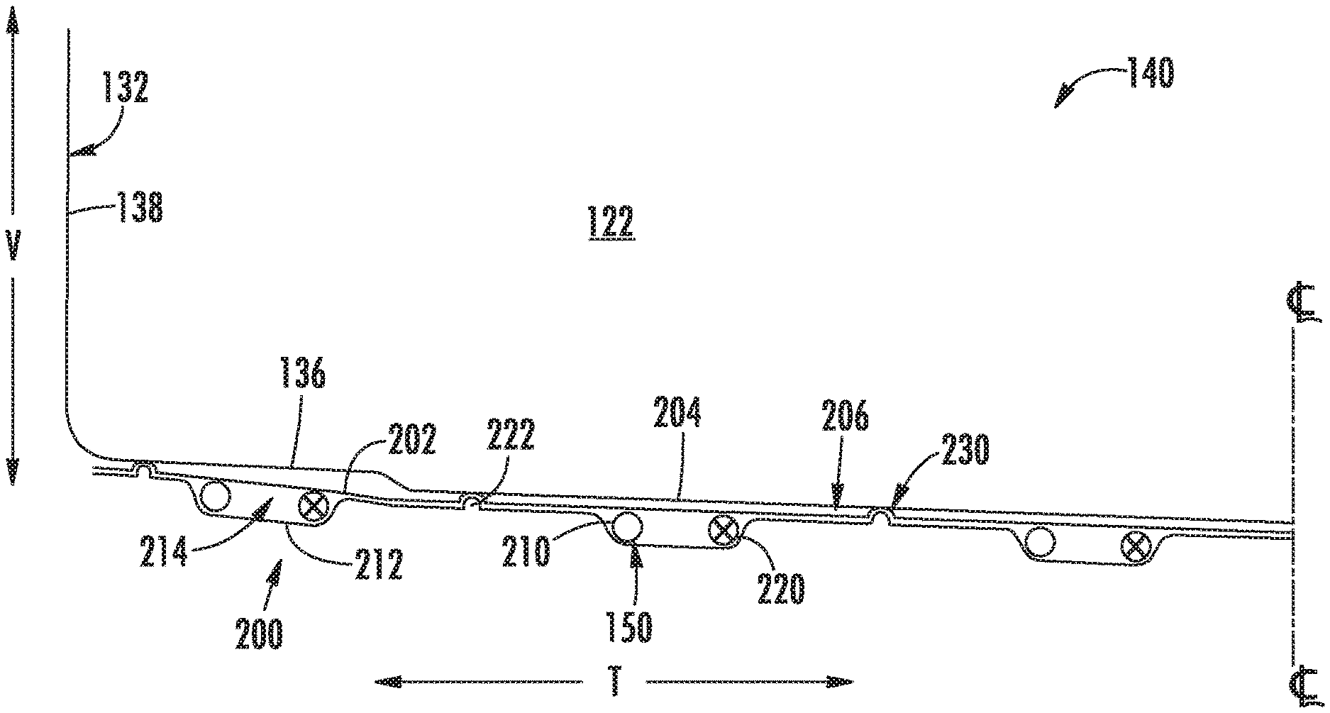
[0013] FIG. 4 is a side cross sectional view of a heating assembly that may be used with the exemplary oven appliance of FIG. 1 according to an exemplary embodiment of the present subject matter.
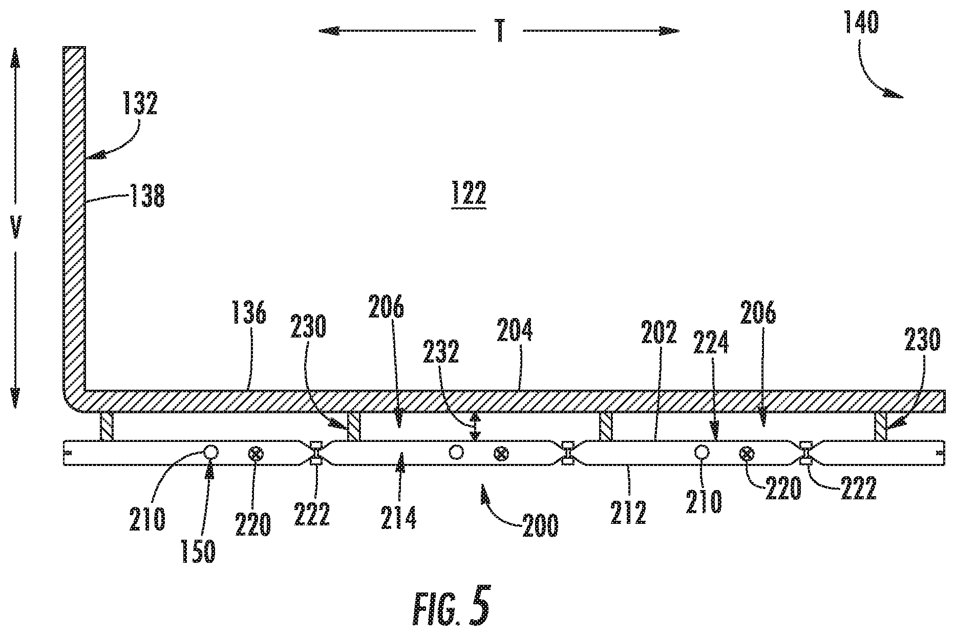
[0014] FIG. 5 is a close up cross sectional view of the exemplary heating assembly of FIG. 4.
[0015] Repeat use of reference characters in the present specification and drawings is intended to represent the same or analogous features or elements of the present invention.
DETAILED DESCRIPTION
[0016] Reference now will be made in detail to embodiments of the invention, one or more examples of which are illustrated in the drawings. Each example is provided by way of explanation of the invention, not limitation of the invention. In fact, it will be apparent to those skilled in the art that various modifications and variations can be made in the present invention without departing from the scope or spirit of the invention. For instance, features illustrated or described as part of one embodiment can be used with another embodiment to yield a still further embodiment. Thus, it is intended that the present invention covers such modifications and variations as come within the scope of the appended claims and their equivalents.
[0017] As used herein, the terms "first," "second," and "third" may be used interchangeably to distinguish one component from another and are not intended to signify location or importance of the individual components. The terms "includes" and "including" are intended to be inclusive in a manner similar to the term "comprising." Similarly, the term "or" is generally intended to be inclusive (i.e., "A or B" is intended to mean "A or B or both"). In addition, it should be appreciated that as used herein, terms of approximation, such as "approximately," "substantially," or "about," refer to being within a ten percent margin of error.
[0018] FIG. 1 provides a front, perspective view of an oven appliance 100 as may be employed with the present subject matter. Oven appliance 100 generally defines a vertical direction V, a lateral direction L, and a transverse direction T, each of which is mutually perpendicular, such that an orthogonal coordinate system is generally defined. As illustrated, oven appliance 100 includes an insulated cabinet 102. Cabinet 102 of oven appliance 100 extends between a top 104 and a bottom 106 along the vertical direction V, between a first side 108 (left side when viewed from front) and a second side 110 (right side when viewed from front) along the lateral direction L, and between a front 112 and a rear 114 along the transverse direction T.
[0019] Within cabinet 102 is an upper cooking chamber 120 and a lower cooking chamber 122 configured for the receipt of one or more food items to be cooked. Thus, oven appliance 100 is generally referred to as a double oven range appliance. However, as will be understood by those skilled in the art, oven appliance 100 is provided by way of example only, and the present subject matter may be used in any suitable cooking appliance. Thus, the present subject matter may be used with other oven appliances such as wall ovens, electric ovens, gas ovens, microwave ovens, etc. In addition, the example embodiment shown in FIG. 1 is not intended to limit the present subject matter to any particular cooking chamber configuration or arrangement.
[0020] Oven appliance 100 includes an upper door 124 and a lower door 126 rotatably attached to cabinet 102 in order to permit selective access to upper cooking chamber 120 and lower cooking chamber 122, respectively. Handles 128 are mounted to upper and lower doors 124 and 126 to assist a user with opening and closing doors 124 and 126 in order to access cooking chambers 120 and 122. As an example, a user can pull on handle 128 mounted to upper door 124 to open or close upper door 124 and access upper cooking chamber 120. Doors 124, 126 may include windows 130, constructed for example from multiple parallel glass panes to provide for viewing the contents of and insulating the insulated cooking chambers 120, 122.
[0021] As illustrated, each of insulated cooking chambers 120, 122 are defined by a plurality of chamber walls, identified generally herein by reference numeral 132. For example, insulated cooking chambers 120, 122 each include a top wall 134 and a bottom wall 136 which are spaced apart along the vertical direction V. A left sidewall and a right sidewall extend between the top wall 134 and bottom wall 136, and are spaced apart along the lateral direction L. A rear wall 138 may additionally extend between the top wall 134 and the bottom wall 136 as well as between the left sidewall and the right sidewall, and is spaced apart from doors 124, 126 along the transverse direction T. In this manner, when doors 124, 126 are in the closed position, cooking cavities are defined, and a front opening 140 is defined for each cooking chamber 120, 122, e.g., proximate front 112 of oven appliance 100.
[0022] Referring to FIG. 1, oven appliance 100 also includes a cooktop 142. Cooktop 142 is positioned at or adjacent top 104 of cabinet 102. Thus, cooktop 142 is positioned above upper cooking chamber 120 and includes a top panel 144 positioned proximate top 104 of cabinet 102. By way of example, top panel 144 may be constructed of glass, ceramics, enameled steel, and combinations thereof. One or more grates 146 are supported on a top surface of top panel 144 for supporting cooking utensils, such as pots or pans, during a cooking process. As shown in FIG. 1, oven appliance 100 may include a plurality of burners assemblies 148 mounted within or on top of top panel 144 underneath grates 146, and such burner assemblies 148 can be configured in various sizes so as to provide e.g., for the receipt of cooking utensils (i.e., pots, pans, etc.) of various sizes and configurations and to provide different heat inputs for such cooking utensils.
[0023] Referring now specifically to FIG. 2, oven appliance 100 may include various heating elements 150, such as electric resistance heating elements, gas burners, microwave heating elements, halogen heating elements, electric tubular heaters (e.g., such as Calrod.RTM. heaters), or suitable combinations thereof. Heating elements 150 are positioned in thermal communication with upper cooking chamber 120 and lower cooking chamber 122 for heating upper cooking chamber 120 and lower cooking chamber 122.
[0024] Specifically, an upper heating element 152 (also referred to as a broil heating element, electric burner, or gas burner) may be positioned in cabinet 102, e.g., at a top portion of cooking chambers 120, 122, and a lower heating element 154 (also referred to as a bake heating element, electric burner, or gas burner) may be positioned proximate a bottom portion of cooking chambers 120, 122. Upper heating element 152 and lower heating element 154 may be used independently or simultaneously to heat cooking chambers 120, 122, perform a baking or broil operation, perform a cleaning cycle, etc. The size and heat output of heating elements 152, 154 can be selected based on, e.g., the size of oven appliance 100 or the desired heat output. Oven appliance 100 may include any other suitable number, type, and configuration of heating elements 150 within cabinet 102 and/or on cooktop 142. For example, oven appliance 100 may further include electric heating elements, induction heating elements, or any other suitable heat generating device.
[0025] One or more baking racks (not shown) may be positioned in insulated cooking chambers 120, 122 for the receipt of food items or utensils containing food items. The baking racks may be slidably received onto embossed ribs or sliding rails such that the baking racks may be conveniently moved into and out of insulated cooking chamber 120, 122 when doors 124, 126 are open.
[0026] A user interface panel 160 is located within convenient reach of a user of the oven appliance 100. For this example embodiment, user interface panel 160 includes knobs 162 that are each associated with one of heating elements 150. In this manner, knobs 162 allow the user to activate each heating element 150 and determine the amount of heat input provided by each heating element 150 to a cooking food items within cooking chamber 120 or on cooktop 142. Although shown with knobs 162, it should be understood that knobs 162 and the configuration of oven appliance 100 shown in FIG. 1 is provided by way of example only. More specifically, user interface panel 160 may include various input components, such as one or more of a variety of touch-type controls, electrical, mechanical or electro-mechanical input devices including rotary dials, push buttons, and touch pads. User interface panel 160 may also be provided with one or more graphical display devices or display components 164, such as a digital or analog display device designed to provide operational feedback or other information to the user such as e.g., whether a particular heating element 150 is activated and/or the rate at which the heating element 150 is set.
[0027] Generally, oven appliance 100 may include a controller 166 in operative communication with user interface panel 160. User interface panel 160 of oven appliance 100 may be in communication with controller 166 via, for example, one or more signal lines or shared communication busses, and signals generated in controller 166 operate oven appliance 100 in response to user input via user input devices 162. Input/Output ("I/O") signals may be routed between controller 166 and various operational components of oven appliance 100 such that operation of oven appliance 100 can be regulated by controller 166. In addition, controller 166 may also be communication with one or more sensors, such as temperature sensor 168 (FIG. 2), which may be used to measure temperature inside cooking chamber 120 and provide such measurements to the controller 166. Although temperature sensor 168 is illustrated at a top and rear of cooking chamber 120, it should be appreciated that other sensor types, positions, and configurations may be used according to alternative embodiments.
[0028] Controller 166 is a "processing device" or "controller" and may be embodied as described herein. Controller 166 may include a memory and one or more microprocessors, microcontrollers, application-specific integrated circuits (ASICS), CPUs or the like, such as general or special purpose microprocessors operable to execute programming instructions or micro-control code associated with operation of oven appliance 100, and controller 166 is not restricted necessarily to a single element. The memory may represent random access memory such as DRAM, or read only memory such as ROM, electrically erasable, programmable read only memory (EEPROM), or FLASH. In one embodiment, the processor executes programming instructions stored in memory. The memory may be a separate component from the processor or may be included onboard within the processor. Alternatively, controller 166 may be constructed without using a microprocessor, e.g., using a combination of discrete analog and/or digital logic circuitry (such as switches, amplifiers, integrators, comparators, flip-flops, AND gates, and the like) to perform control functionality instead of relying upon software.
[0029] Although aspects of the present subject matter are described herein in the context of a double oven appliance including a cooktop, it should be appreciated that oven appliance 100 is provided by way of example only. In this regard, the present subject matter is not limited to any particular style, model, or configuration of oven appliance 100. For example, other oven or range appliances having different configurations, different appearances, and/or different features may also be utilized with the present subject matter as well, e.g., single ovens, electric cooktop ovens, gas cooktops ovens, etc. Moreover, aspects of the present subject matter may be used in any other consumer or commercial appliance where it is desirable to efficiently heat a cooking chamber.
[0030] Referring now generally to FIGS. 2 through 5, a heating assembly 200 which may be used to heat cooking chambers 120, 122 of oven appliance 100 will be described according to an exemplary embodiment of the present subject matter. Specifically, according to the illustrated embodiment, oven appliance 100 may include two heating assemblies 200, each being placed in thermal communication with one of upper cooking chamber 120 and lower cooking chamber 122. In general, heating assemblies 200 are illustrated as low-profile bake assemblies (replacing lower heating elements 154), but could alternatively replace upper heating elements 152 or may be configured in any other suitable manner within other appliance 100. The exemplary embodiment described herein is not intended to limit the scope of the present subject matter in any manner.
[0031] Referring for example to heating assembly 200 positioned below lower cooking chamber 122, e.g., outside lower cooking chamber 122 beneath bottom wall 136 along the vertical direction V. Heating assembly 200 generally includes an upper plate or a first plate 202 which is spaced apart from chamber wall 204 (e.g., bottom wall 136) to define an airgap 206 therebetween. In addition, heating assembly 200 includes a heating element 210 (e.g., such as lower heating element 154) which is positioned adjacent to first plate 202 opposite from airgap 206. In other words, first plate 202 and airgap 206 are positioned between chamber wall 204 and heating element 210. As explained in more detail below, airgap 206 serves to distribute heat generated by a heating element 210.
[0032] As used herein, the term "airgap" is intended to refer to an open space defined between chamber wall 204 and first plate 202. Airgap 206 generally contains no appliance components or features, leaving a substantially open space through which air may circulate to distribute heat generated by heating elements 210. However, it should be appreciated that airgap 206 may include various features for directing air or spreading the flow of heat within airgap 206, such as baffles, flow guiding features, or other components. In addition, although airgap 206 is illustrated as a passive thermal distribution system, active air flow features may be used according to alternative embodiments. In this regard, for example, one or more fans may be used to circulate air within airgap 206.
[0033] As shown, heating assembly 200 may further include a lower plate or a second plate 212 that is coupled to first plate 202 to define a heater cavity 214. As illustrated, heating element 210 is positioned with in heater cavity 214. In addition to heating element 210, heating assembly 200 may further include a service heater 220 that is also positioned within heater cavity 214. Service heater 220 may be identical to heating element 210 (e.g., may be a heating element 150) but is not hooked up, powered, or otherwise energized for producing heat unless and until heating element 210 fails. If heating element 210 fails, a repair technician may disconnect heating element 210 and can connect service heater 222 to a power source and/or controller 166, which may then operate service heater 220 as a redundant backup to the inoperative heating element 210.
[0034] According to exemplary embodiments, first plate 202 and second plate 212 are upper and lower plates that extend substantially along the entire width and depth of chamber wall 204, e.g., bottom wall 136. First plate 202 and second plate 212 may be riveted or otherwise fastened together to define heater cavity 214 for receiving heating element 210 and/or service heater 220. Specifically, when assembled, first plate 202 and second plate 212 may extend between rear wall 138 and front opening 140 along the transverse direction T, and along the lateral direction L between a first side wall and a second side wall of lower cooking chamber 122 (or any other suitable cooking chamber). First plate 202 and second plate 212 may be fastened together in any suitable manner. For example, according to the illustrated embodiment, first plate 202 and second plate 212 are joined using one or more fastening joints or rivets 222. By contrast according to alternative embodiments, first plate 202 and second plate 212 may be joined using any other suitable mechanical fastener, by welding, or may be a single sheet of metal that is bent or otherwise formed to define heater cavities 214.
[0035] First plate 202 and second plate 212 may be constructed from any suitable material and may have any suitable size and configuration for improving the distribution of heat energy along the entire chamber wall 204. For example, according to the illustrated embodiment, first plate 202 and second plate 212 are formed from aluminized steel to provide good heat conduction. In addition, according to exemplary embodiments, first plate 202 and second plate 212 may include a coating 224 that minimizes transfer of heat through thermal infrared radiation. For example, such coating 224 may be an aluminum ceramic paint or another low infrared emitting coating or plating.
[0036] Heating assembly 200 may further include standoff features 230 which are defined on first plate 202 or on chamber wall 204 for defining airgap 206. Specifically, according to the illustrated embodiment, standoff features 230 are simple metal brackets that extend from first plate 202 toward chamber wall 204 and seat against the chamber wall 204 to maintain a constant airgap 206. Alternatively, rivets 222 may be formed such that they have an extension or otherwise protrude from first plate 202 to define airgap 206.
[0037] As illustrated, airgap 206 may define a gap size (e.g. identified herein by reference numeral 232, see FIG. 5) which is substantially constant along an entire width and depth of chamber wall 204. In this regard, airgap 206 extends along the transverse direction T between rear wall 138 in front opening 140 and along the lateral direction L between a first side wall and a second side wall of cooking chamber 122. According to exemplary embodiments, gap size 232 may be less than about 20 millimeters, less than 10 millimeters, or less than 5 millimeters. Alternatively, gap size 232 may be greater than 1 mm, greater than 3 millimeters, or greater than 5 millimeters. In addition, although airgap 206 is illustrated herein as having a constant gap size 232, it should be appreciated that according to alternative embodiments, gap size 232 may vary a long a width and depth of chamber wall 204.
[0038] As described above, heating assembly 200 includes features for efficiently distributing thermal energy from heating elements 210 along an entire width and depth of chamber wall 204. In this regard, first plate 202 and second plate 212 facilitate improved conduction away from heating elements 210 along a width and depth of plates 202, 212. In addition, first plate 202 minimizes direct radiant energy onto chamber wall 204. Furthermore, airgap 206 provides for homogenization of air heated by heating elements 210. Thus, hot air may circulate within airgap 206 to provide uniform heating to chamber wall 204. In this manner, heating elements 210 may be operated at a higher power relative to conventional heating elements, due in part to the uniform heating and the elimination of hotspots which would otherwise limit the maximum heating power. Thus, while maintaining acceptable watt density, the total thermal power crossing chamber wall 204 may increase, preheat times may be reduced, and user satisfaction may be improved.
[0039] This written description uses examples to disclose the invention, including the best mode, and also to enable any person skilled in the art to practice the invention, including making and using any devices or systems and performing any incorporated methods. The patentable scope of the invention is defined by the claims, and may include other examples that occur to those skilled in the art. Such other examples are intended to be within the scope of the claims if they include structural elements that do not differ from the literal language of the claims, or if they include equivalent structural elements with insubstantial differences from the literal languages of the claims.
* * * * *
D00000
D00001
D00002
D00003
D00004
XML
uspto.report is an independent third-party trademark research tool that is not affiliated, endorsed, or sponsored by the United States Patent and Trademark Office (USPTO) or any other governmental organization. The information provided by uspto.report is based on publicly available data at the time of writing and is intended for informational purposes only.
While we strive to provide accurate and up-to-date information, we do not guarantee the accuracy, completeness, reliability, or suitability of the information displayed on this site. The use of this site is at your own risk. Any reliance you place on such information is therefore strictly at your own risk.
All official trademark data, including owner information, should be verified by visiting the official USPTO website at www.uspto.gov. This site is not intended to replace professional legal advice and should not be used as a substitute for consulting with a legal professional who is knowledgeable about trademark law.