Unloader For A Compressor And Servicing Thereof And Compressor Provided With An Unloader
MARTENS; Kristof Adrien ; et al.
U.S. patent application number 16/962400 was filed with the patent office on 2021-01-07 for unloader for a compressor and servicing thereof and compressor provided with an unloader. This patent application is currently assigned to ATLAS COPCO AIRPOWER, NAAMLOZE VENNOOTSCHAP. The applicant listed for this patent is ATLAS COPCO AIRPOWER, NAAMLOZE VENNOOTSCHAP. Invention is credited to Pieter DE SCHAMPHELAERE, Kristof Adrien MARTENS, Daniel Joseph SMITH.
| Application Number | 20210003125 16/962400 |
| Document ID | / |
| Family ID | |
| Filed Date | 2021-01-07 |
| United States Patent Application | 20210003125 |
| Kind Code | A1 |
| MARTENS; Kristof Adrien ; et al. | January 7, 2021 |
UNLOADER FOR A COMPRESSOR AND SERVICING THEREOF AND COMPRESSOR PROVIDED WITH AN UNLOADER
Abstract
Unloader for a compressor, said unloader (1) comprising a housing (2) with an inlet (3) and an outlet (4), and whereby the unloader (1) is further provided with a piston rod (5) which is arranged moveably in a reciprocating manner in the housing (2), whereby on one end (5a) of the piston rod (5) a valve (7) is provided to be able to close the outlet (4) and whereby on the other end (5b) of the piston rod (5) a piston (8) is arranged, the piston being arranged moveably in a reciprocating manner in a thereto provided cavity (9) of the unloader (1), said cavity (9) being at least partially delimited by a lid (10) which is provided on the housing (2) and which is also part of the unloader (1), whereby sealing means (11) are provided for the leakage-free movement of the piston (8) in said cavity (9), whereby the cavity (9) in which the piston (8) is arranged moveably in a reciprocating manner is provided at least partially in the lid (10).
| Inventors: | MARTENS; Kristof Adrien; (Wilrijk, BE) ; DE SCHAMPHELAERE; Pieter; (Wilrijk, BE) ; SMITH; Daniel Joseph; (Wilrijk, BE) | ||||||||||
| Applicant: |
|
||||||||||
|---|---|---|---|---|---|---|---|---|---|---|---|
| Assignee: | ATLAS COPCO AIRPOWER, NAAMLOZE
VENNOOTSCHAP Wilrijk BE |
||||||||||
| Appl. No.: | 16/962400 | ||||||||||
| Filed: | May 17, 2018 | ||||||||||
| PCT Filed: | May 17, 2018 | ||||||||||
| PCT NO: | PCT/IB2018/053462 | ||||||||||
| 371 Date: | July 15, 2020 |
| Current U.S. Class: | 1/1 |
| International Class: | F04B 49/03 20060101 F04B049/03; F04B 49/22 20060101 F04B049/22; F01L 9/02 20060101 F01L009/02 |
Foreign Application Data
| Date | Code | Application Number |
|---|---|---|
| Feb 9, 2018 | BE | 2018/5079 |
Claims
1-11. (canceled)
12. An unloader for a compressor, said unloader (1) comprising a housing (2) with an inlet (3) and an outlet (4), and whereby the unloader (1) is further provided with a piston rod (5) which is arranged moveably in a reciprocating manner in the housing (2), whereby on one end (5a) of the piston rod (5) a valve (7) is provided to be able to close the outlet (4) and whereby on the other end (5b) of the piston rod (5) a piston (8) is arranged, the piston being arranged moveably in a reciprocating manner in a thereto provided cavity (9) of the unloader (1), said cavity (9) being at least partially delimited by a lid (10) which is provided on the housing (2) and which is also part of the unloader (1), whereby sealing means (11) are provided for the leakage-free movement of the piston (8) in said cavity (9), wherein the cavity (9) in which the piston (8) is arranged moveably in a reciprocating manner is completely located or integrated in the lid (10), and the piston (8) and the sealing means (11) are freely accessible when the lid (10) is removed.
13. The unloader according to claim 12, the lid (10) is executed as a cylindrical casing (13) and a hood (14) whereby the piston (8) is arranged moveably in a reciprocating manner in the casing (13).
14. The unloader according to claim 12, sealing means (11) are provided between a sealing surface of the piston (8) and a sealing surface of the lid (10).
15. The unloader according to claim 12, said sealing means (11) comprise a seal (18) and/or a slide ring (17).
16. The unloader according to claim 15, said sealing means (11) comprise a seal (18), and that this seal (18) comprises a single-acting seal (18).
17. The unloader according to claim 12, the lid (10) is mounted detachably on the housing (2) by means of bolts (12).
18. The unloader according to claim 12, the lid (10) is provided with a handle or handgrip (16).
19. A method to replace the sealing means of an unloader (1) according to claim 12, said method comprising the following steps: dismantling the lid (10) of the housing (2) such that the piston (8) becomes freely available, replacing one or several sealing means (11), mounting the lid (10).
20. A compressor provided with a compressor element with an inlet for gas to be compressed and an outlet for compressed gas, the compressor is provided with an unloader (1) according to claim 12, said unloader (1) being connected with its outlet (4) to said inlet for gas to be compressed.
Description
[0001] The present invention relates to an unloader for a compressor and more specifically an unloader with improved servicing.
[0002] An unloader is a valve which is mounted on the level of the inlet of a compressor and which will control the amount of air a compressor can suck in. By opening and closing the compressor's air inlet using the unloader, the capacity of the compressor can be controlled.
[0003] A problem with existing unloaders is in the servicing of the unloader, whereby the seal and the slide ring need to be replaced at regular times, approximately annually. To this end the unloader needs to be demounted.
[0004] In the existing unloader of FIG. 1 for example, the unloader needs to be detached from the compressor and subsequently the lid needs to be removed by unscrewing eight prestressed bolts to replace the seal and the slide ring. Subsequently the piston rod can be uncoupled from the piston by taking apart the ring, the screw and the washer. In short, many actions are required to get to the seal and the slide ring. Consequently, there is a greater risk of errors or mistakes.
[0005] Moreover, all these actions need to be performed again in the reverse order to mount the unloader on the compressor again after replacement of the seal and the slide ring.
[0006] Another problem is that a typical unloader weighs approximately thirty kilogrammes, making demounting of the unloader from the compressor a hard job.
[0007] An additional problem is that the compressor, once the unloader has been removed, shows a big opening in which dirt or the like can end up. This dirt ends up directly in the inlet of the compressor and can cause considerable damage there.
[0008] Another problem occurs when mounting it again after servicing. After installation, the seal on the piston will be fixed in the unloader largely blindly and using force, such that it can be damaged, resulting in an inadequate sealing.
[0009] U.S. Pat. No. 6,397,892 describes a similar known type of unloader to vary the internal volume of a reciprocating compressor cylinder. On dismantling it for servicing, the whole lid, consisting of the components 76, 74, 78, 72 and 40, needs to be unscrewed. However, the piston rod is not exposed hereby, such that it is not possible to replace the seal and/or the slide ring of the piston.
[0010] The purpose of the present invention is to provide a solution to at least one of the aforementioned and/or other disadvantages.
[0011] To this end, the invention relates to an unloader for a compressor, the unloader comprising a housing with an inlet and an outlet, and whereby the unloader is further provided with a piston rod which is arranged moveably in a reciprocating manner in the housing, whereby on one end of the piston rod a valve is provided to be able to close the outlet and whereby on the other end of the piston rod a piston is arranged, the piston being arranged moveably in a reciprocating manner in a thereto provided cavity of the unloader, said cavity being at least partially delimited by a lid which is provided on the housing and which is also part of the unloader, whereby sealing means are provided for the leakage-free movement of the piston in said cavity, characterised in that the cavity in which the piston is arranged moveably in a reciprocating manner is provided at least partially in the lid.
[0012] The advantages are that the lid is made such that by removing the lid, the slide ring and the seal are easily accessible.
[0013] Consequently, the entire unloader does not have to be demounted to replace the sealing means. Only the lid needs to be removed, whereby this lid only weighs a fraction of the entire unloader, typically only one and a half kilogrammes, and consequently is much easier to handle.
[0014] The consequence is also that the number of actions that has to be performed to replace the sealing means can be limited. For example, the piston rod no longer has to be detached from the piston.
[0015] Moreover, the inlet opening of the compressor will not be exposed, such that there is no risk that dirt or the like will end up in the compressor.
[0016] It is not excluded for the invention that the cavity is entirely provided in the lid.
[0017] In a preferred embodiment the lid is made as a cylindrical casing and a hood whereby the piston is arranged moveably in a reciprocating manner in the casing.
[0018] Alternatively, the lid can for example also be made thicker and provided with a shaft in which the piston is arranged moveably in a reciprocating manner.
[0019] In a special embodiment the sealing means are provided between a sealing surface of the piston and a sealing surface of the lid.
[0020] This means the sealing means will ensure the sealing between the piston and the cavity in the lid. Said sealing surfaces of the piston and the lid will come into contact with each other.
[0021] In another embodiment said sealing means of the piston comprise a seal and/or a slide ring.
[0022] This seal can for example comprise a single-acting seal.
[0023] Preferably, the lid is attached detachably on the housing by means of bolts.
[0024] In a special embodiment, said cavity is entirely integrated or located in the lid.
[0025] The piston and the sealing means are freely accessible when the lid is removed.
[0026] In a specific embodiment, the lid is provided with a handle or handgrip.
[0027] The invention also relates to a method to replace the sealing means of an unloader as described above, said method comprising the following steps: [0028] a) demounting the lid of the housing such that the piston becomes freely accessible; [0029] b) replacing one or several sealing means; and [0030] c) mounting the lid on the housing.
[0031] The invention also relates to a compressor provided with a compressor element with an inlet for gas to be compressed and an outlet for compressed gas, said compressor being provided with an unloader with the characteristics of claim 1, said unloader with its outlet being connected to said inlet for gas to be compressed.
[0032] With the intention of better showing the characteristics of the invention, a preferred embodiment of an unloader according to the invention is described hereinafter, by way of an example without any limiting nature, with reference to the accompanying drawings wherein:
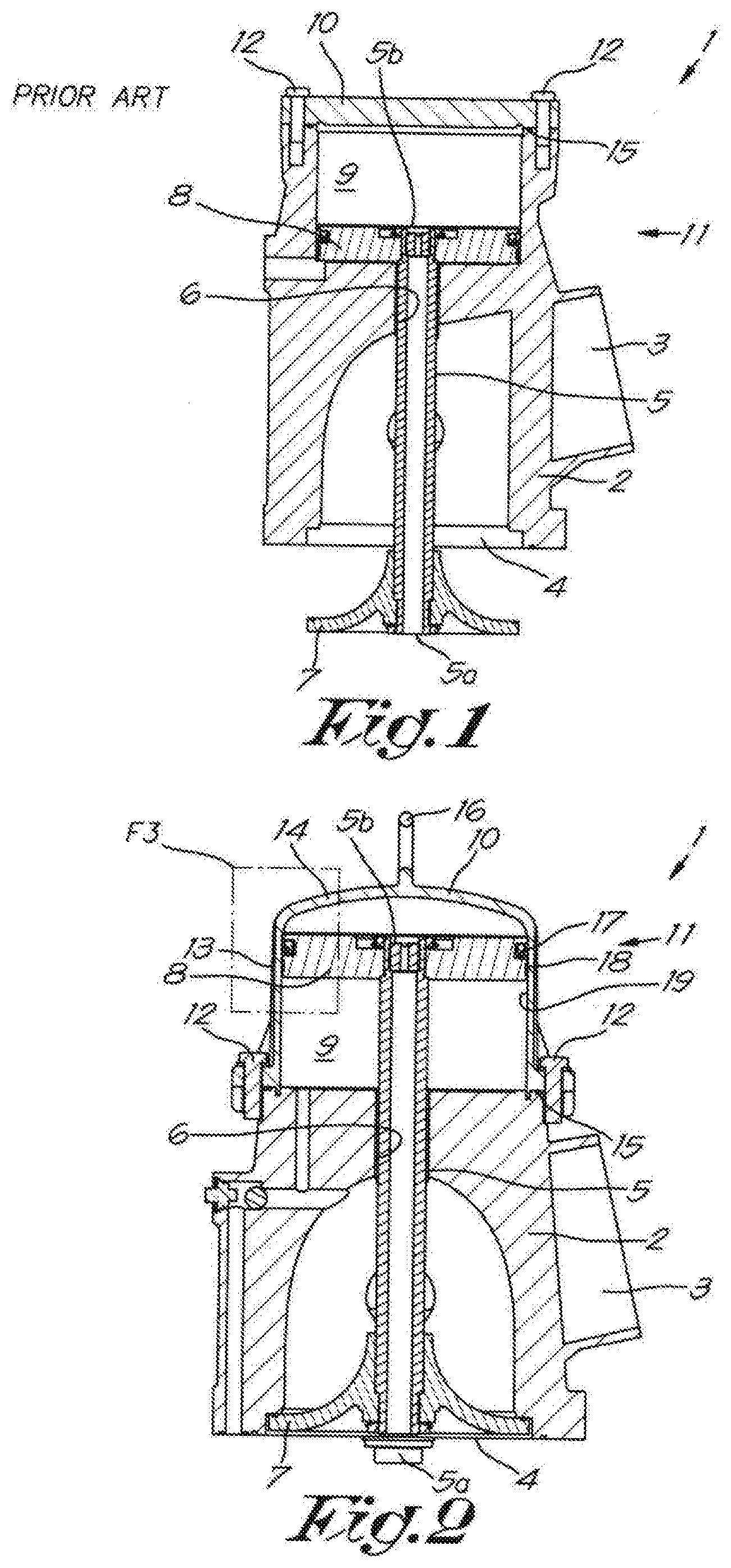
[0033] FIG. 1 schematically shows an existing embodiment of an unloader;
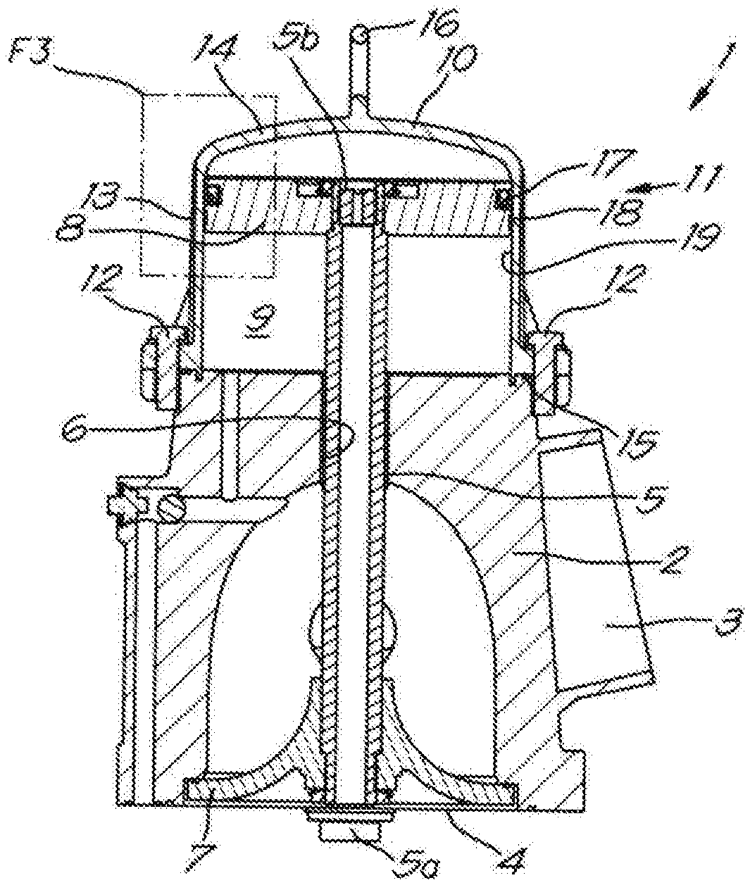
[0034] FIG. 2 schematically shows a preferred embodiment of a mounted unloader according to the invention;
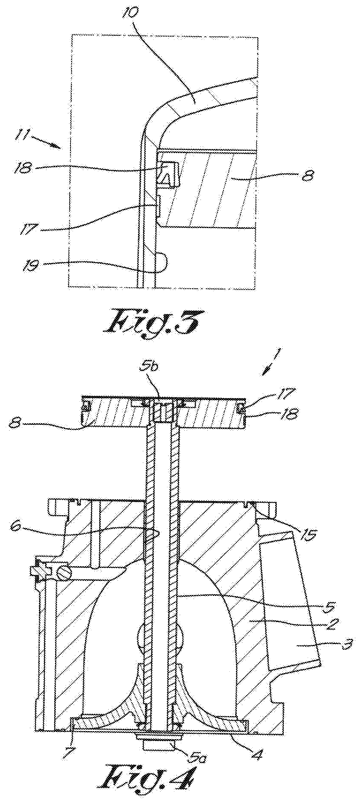
[0035] FIG. 3 schematically shows the section indicated in FIG. 2 with F3; and
[0036] FIG. 4 schematically shows a preferred embodiment of a demounted unloader according to the invention.
[0037] FIG. 1 shows an existing embodiment of an unloader 1.
[0038] The unloader 1 comprises a housing 2 with an inlet 3 and an outlet 4.
[0039] The outlet 4 is intended to be connected to the inlet of a compressor. The inlet 3 of the unloader 1 can be provided with or connected to an inlet filter, which will purify the gas that is sucked in by the compressor.
[0040] The unloader 1 is further provided with a piston rod 5 which is arranged moveably in a reciprocating manner in the unloader 1 in a shaft 6 provided for this purpose in the housing 2.
[0041] On one end 5a the piston rod 5 is provided with a valve 7 to be able to close said outlet 4 by the reciprocating movement of the piston rod 5 in the housing 2.
[0042] On the other end 5b of the piston rod 5, a piston 8 has been arranged moveably in a reciprocating manner in a thereto provided cavity 9 of the unloader 1.
[0043] The cavity 9 is provided in the housing 2 and is at least partially delimited by a lid 10 that can be mounted on the housing 2.
[0044] As can be clearly deducted from FIG. 1, the reciprocating movement of the piston 8 in the cavity 9 in the known way allows the valve 7 to be moved to close the outlet 4 of the unloader 1 or not.
[0045] To move the piston 8, use is made of a pressure difference in the cavity 9 between the top and bottom of the piston 8. To avoid the leakage of gas over the piston 8 as a result of this pressure difference, sealing means 11 have been provided which are applied on the contour of the piston 8.
[0046] To replace these sealing means 11, the unloader 1 of the compressor needs to be removed and subsequently the lid 10 needs to be removed by unscrewing the prestressed bolts 12. Subsequently the valve 7 can be detached from the piston rod 5 and the piston 8 can be taken out of the unloader 1 by lifting the piston rod 5 until the piston 8 lifts out of the cavity 9, to then remove and replace the sealing means 11.
[0047] FIG. 2 shows a mounted unloader 1 according to the invention.
[0048] The structure of the unloader 1 partially corresponds with the structure of the known unloader of FIG. 1.
[0049] An important difference is that said cavity 9 in this case is provided in the lid 10. To this end, in this example, the lid 10 is made as a cylindrical casing 13 and a hood 14 or in other words, like a kind of `hat` on a housing 2 flattened at the top. Between the lid 10 and the housing 2, in this case a seal, for example in the form of an O-ring 15, is provided, however, according to the invention this is not strictly necessary. Evidently, another type of seal, other than an O-ring, can also be applied. The cavity 9 is situated as a free inner space between the lid 10 and the housing 2.
[0050] According to a preferred characteristic of the invention, the lid 10 is further provided with a handle or handgrip 16 which, in this example, is provided on top of the lid 10, but can also be provided on a side thereof.
[0051] The piston rod 5 runs via a shaft 6 in the housing 2 into said free space 9 under the lid 10, such that the piston 8 can move up and down in the lid 10, more specifically in said cavity 9 or free inner space.
[0052] On its contour, the piston 8 is provided with sealing means 11, as shown in FIG. 3. They comprise a slide ring 17 and a seal 18 in this example, which ensure the sealing between the piston 8 and the inside 19 of the lid 10.
[0053] In this case, the seal 18 is a single-acting seal 18, as shown in the figure. This means that it will seal completely in one direction. In this case in the direction of the valve 7 toward the top of the lid 10. The invention is not limited to an embodiment comprising a slide ring 17 and a seal 18, however, there are also other possibilities to execute said sealing means, for example by only providing a seal 18 or only a slide ring 17.
[0054] To replace the seal 18 and the slide ring 17 in this case only the lid 10 needs to be unscrewed and removed from the housing 2 by unscrewing the bolts 12 and lifting up the lid 10 using the handle or handgrip 16, as shown in the FIGS. 2 and 4.
[0055] It goes without saying that the connection between the housing 2 and the lid 10 can be realised in all kinds of ways and is not limited to a bolt connection. For example, clamping means, screws or the like can be used.
[0056] By removing the lid 10, the contour of the piston 8 is free and the seal 18 and the slide ring 17 are easily accessible for replacement, by taking them out and putting in a new seal 18 and/or slide ring 17. The seal 18 and the slide ring 17 also remain in place correctly when the lid 10 is put over the piston 8 on the housing 2 and tightened by means of the bolts 12. The piston rod 5 stays fixed in the shaft 6 of the housing 2. Furthermore, when putting the lid 10 back on the housing 2, the lid 10 will slide from top to bottom over the single-acting seal 18, whereby this seal 18 cannot be damaged.
[0057] Other advantages are that there is no need to demount the entire unloader 1 from the compressor as the housing 2 can remain mounted on the inlet of the compressor, and that the piston 8 and/or the valve 7 do not need to be detached from the piston rod 5. Further, the inlet of the compressor remains sealed against dirt, as the unloader 1 itself will not be demounted.
[0058] The present invention is by no means limited to the embodiments described as an example and shown in the drawings, but an unloader according to the invention as defined by the claims can be realised according to all kinds of variants without departing from the scope of the invention.
* * * * *
D00000
D00001
D00002
XML
uspto.report is an independent third-party trademark research tool that is not affiliated, endorsed, or sponsored by the United States Patent and Trademark Office (USPTO) or any other governmental organization. The information provided by uspto.report is based on publicly available data at the time of writing and is intended for informational purposes only.
While we strive to provide accurate and up-to-date information, we do not guarantee the accuracy, completeness, reliability, or suitability of the information displayed on this site. The use of this site is at your own risk. Any reliance you place on such information is therefore strictly at your own risk.
All official trademark data, including owner information, should be verified by visiting the official USPTO website at www.uspto.gov. This site is not intended to replace professional legal advice and should not be used as a substitute for consulting with a legal professional who is knowledgeable about trademark law.