Switches For Controlling Downhole Tools
ROESSLER; Dennis E.
U.S. patent application number 16/976127 was filed with the patent office on 2021-01-07 for switches for controlling downhole tools. This patent application is currently assigned to GEODYNAMICS, INC.. The applicant listed for this patent is GEODYNAMICS, INC.. Invention is credited to Dennis E. ROESSLER.
| Application Number | 20210002981 16/976127 |
| Document ID | / |
| Family ID | |
| Filed Date | 2021-01-07 |


View All Diagrams
| United States Patent Application | 20210002981 |
| Kind Code | A1 |
| ROESSLER; Dennis E. | January 7, 2021 |
SWITCHES FOR CONTROLLING DOWNHOLE TOOLS
Abstract
A downhole tool for time delaying a downhole activity. The downhole tool includes a housing having a bore; a moving sleeve configured to move relative to the housing; an electronic valve configured to open and close when receiving an electrical signal; and a switch that is responsive to a fluid pressure inside the bore. The downhole tool electronically counts down a set time.
| Inventors: | ROESSLER; Dennis E.; (Fort Worth, TX) | ||||||||||
| Applicant: |
|
||||||||||
|---|---|---|---|---|---|---|---|---|---|---|---|
| Assignee: | GEODYNAMICS, INC. Millsap TX |
||||||||||
| Appl. No.: | 16/976127 | ||||||||||
| Filed: | March 11, 2019 | ||||||||||
| PCT Filed: | March 11, 2019 | ||||||||||
| PCT NO: | PCT/US19/21565 | ||||||||||
| 371 Date: | August 27, 2020 |
Related U.S. Patent Documents
| Application Number | Filing Date | Patent Number | ||
|---|---|---|---|---|
| 62648985 | Mar 28, 2018 | |||
| Current U.S. Class: | 1/1 |
| International Class: | E21B 34/14 20060101 E21B034/14; E21B 34/06 20060101 E21B034/06 |
Claims
1. A downhole tool for time delaying a downhole activity, the downhole tool comprising: a housing having a bore; a moving sleeve configured to move relative to the housing; an electronic valve configured to open and close when receiving an electrical signal; and a switch that is responsive to a fluid pressure inside the bore, wherein the downhole tool electronically counts down a set time.
2. The tool of claim 1, wherein the switch is configured to close an electrical circuit to energize an electronic block.
3. The tool of claim 2, wherein the switch is electrically wired to the electronic block.
4. The tool of claim 3, wherein the electronic valve is electrically wired to the electronic block.
5. The tool of claim 4, wherein the electronic block includes a timer that counts down the set time.
6. The tool of claim 5, wherein the timer counts down the set time after being energized and sends a command to a dump valve of the electronic valve to open.
7. The tool of claim 6, wherein the electronic valve, when opened, allows a fluid from the bore to reach the moving sleeve and move the moving sleeve.
8. The tool of claim 5, wherein the electronic block includes a power source.
9. The tool of claim 1, wherein the switch includes a biasing mechanism that resets the switch.
10. The tool of claim 1, wherein the switch includes a first pressure responsive switch and a second, resettable, pressure responsive switch.
11. The tool of claim 1, wherein the switch includes a first pressure responsive switch and a second switch that includes a pressure transducer.
12. The tool of claim 1, wherein the switch includes a first pressure responsive switch and a second switch that includes a velocity transducer.
13. The tool of claim 1, wherein the tool is a toe valve.
14. The tool of claim 1, wherein the tool is a setting tool.
15. A switch-valve assembly to actuate a downhole tool, the switch-valve assembly comprising: a switch located to have a part exposed to a fluid pressure associated with the downhole tool; an electronic block electrically connected to the switch; and an electronic valve electrically connected to the electronic block and configured to open and close when receiving an electrical signal from the electronic block, wherein the electronic block counts down a set time.
16. The assembly of claim 15, wherein the switch is configured to close an electrical circuit to energize the electronic block.
17. The assembly of claim 15, wherein the switch includes a biasing mechanism that resets the switch.
18. The assembly of claim 15, wherein the switch includes a first pressure responsive switch and a second, resettable, pressure responsive switch.
19. The assembly of claim 15, wherein the switch includes a first pressure responsive switch and a second switch that includes a pressure transducer.
20. The assembly of claim 15, wherein the switch includes a first pressure responsive switch and a second switch that includes a velocity transducer.
21. A method for actuating a downhole tool in a wellbore, the method comprising: lowering the downhole tool into the wellbore; increasing a pressure into the wellbore above a threshold pressure of a pressure responsive switch to close the switch; energizing an electronic block associated with the pressure responsive switch; starting a timer of the electronic block; and sending a command from the electronic block to an electronic valve at the end of a set time of the timer.
22. The method of claim 21, further comprising: decreasing the pressure into the wellbore to open the switch.
23. The method of claim 22, further comprising: resetting the timer when the switch is opened.
Description
BACKGROUND
Technical Field
[0001] Embodiments of the subject matter disclosed herein generally relate to downhole tools used for perforating and/or fracturing operations in a wellbore, and more specifically, to a pressure responsive switch that controls an action associated with a downhole tool.
Discussion of the Background
[0002] It has become a common practice to install a pressure responsive opening device at the bottom or toe of a casing string within horizontal well bores and in some vertical bores. These devices make up and run as an integral part of the casing string. After the casing has been cemented and the cement has been allowed to solidify, surface pressure is applied to the fluid inside the casing, which combined with the hydrostatic pressure of that fluid, makes a pressure responsive valve to open. The combination of hydrostatic and applied pressure is customarily used to overcome a number of shear pins or to overcome a precision rupture disc for actuating the valve.
[0003] After the pressure responsive valve has opened, communication between the bore of the casing and a formation (i.e., volume outside of the casing) around the well is achieved. At this time, the well can be hydraulically fractured or the valve can be used as an injection port to pump down wire line perforating guns, plugs or other conveyance means such as well tractors. Other known methods of establishing communication with the cemented and cased well include tubing conveyed or coil tubing conveyed perforators. These are all common methods to achieve an injection point, but they require increased time and money.
[0004] The pressure responsive valve is only one example of a downhole tool that may be activated by the pressure inside the well. Anther downhole tool that works in a similar way is the wellbore setting tool. Other downhole tools may use a similar technology. These pressure responsive tools rely on a burst disc that is typically ruptured by the increased well pressure. If the well pressure is suddenly applied to an interior mechanism of the pressure responsive tool, the tool may open instantaneously, in an uncontrolled manner, where a piston or sleeve slams a housing in an uncontrolled manner.
[0005] Therefore, there is a need for a pressure responsive tool that includes a time delay device for slowing down the move of the piston or sleeve. Such a device is shown in FIGS. 1A and 1B. FIG. 1A illustrates a controlled time delay tool 100 (e.g., toe valve apparatus) that is configured to be integrated into the casing string. FIG. 1B shows the controlled time delay tool 100 having an inner mandrel 29, that is inserted directly into the casing string. Slotted ports 28 allow fluid communication between the geologic formation surrounding the casing and the bore of the casing. The integral one-piece design of the mandrel carries all of the tensile, compressional and torsional loads encountered by the apparatus. The entire toe valve apparatus 100 is piped into the casing string as an integral part of the string and positioned where perforation of the formation and fluid injection into the formation is desired. The apparatus may be installed in either direction with no change in its function.
[0006] The structure of the toe valve apparatus 100 is now discussed with regard to FIG. 1B. FIG. 1B shows a pressure activated opening device 23, e.g., the conventional rupture disc. The mandrel is machined to accept the opening device 23 that ultimately controls an actuation of the piston 5. The piston 5 covers the inner and outer ports 25-27 and 28, in the apparatus, when in the closed state. Note that the inner ports 25-27 are formed in the mandrel 29 while the outer ports 28 are formed into a cover 6 or 8. A series of outer sections 4, 6, and 8 are threadedly connected to each other and to the mandrel 20 to form the fluid and pressure chambers 32 and 34 for the apparatus. The tandem 3, not only couples outer sections 4 and 6, but also houses a hydraulic restrictor 22. The chamber 32, to the left of the piston 5, is a fluid chamber and the chamber to the left of tandem 3 is the low pressure chamber 34 that accommodates the fluid volume from the fluid chamber 32 as it traverses across the hydraulic restrictor. The chambers are both capped by the upper cap 8.
[0007] The rupture disc 23 is the activation device that sets the valve opening operation into play. When ready to operate (i.e., open the piston), the casing pressure is increased to a test pressure condition. This increased pressure ruptures the rupture disc 23 and fluid at casing pressure (hydrostatic, applied or any combination) enters the chamber immediately below and adjacent to the piston 5. This entry of fluid causes the piston 5 to begin moving (to the left in the drawings). This fluid movement allows the piston to move inexorably closer to an open position. Inner ports 25-27 and the outer port 28 are initially closed or sealed off from the casing fluid by the piston 5. As piston 5 moves toward the open and final position, the ports 28, are uncovered allowing fluid to flow through ports 25, 26 and 27 through slots 28.
[0008] After the disc 23 is ruptured, piston 5 moves inside chamber 32, thus displacing the fluid in this chamber. This movement continues until the piston has moved to a position where the ports are fully opened. Piston 5 surrounds the inter wall of the mandrel 29. As fluid pressure increases through port 14, piston 5 displaces the fluid from the fluid chamber 32, into chamber 34, through the restrictor 22. The slow movement of the hydraulic fluid from the fluid chamber 32 to the chamber 34 restrains the movement of the piston 5. This flow restrictor 22 controls the rate of flow of fluid from chamber 32 to chamber 34 and thereby controls the speed of the movement of the piston as it moves to the full open position. Initially, this movement increases pressure in the fluid chamber to a value that closely reflects the hydrostatic plus applied casing pressure. There is considerable predetermined control over the delay time by learned manipulation of the fluid type, fluid volume, initial charging pressure of the low pressure chamber and the variable flow rate through the hydraulic restrictor. The time delay can be set as desired but generally will be about 5 to 60 minutes. Any hydraulic fluid will be suitable if capable of withstanding the pressure and temperature conditions that exist in the well bore.
[0009] However, these controlled devices and systems have limitations which include a lack of flexibility to change the timing, and the lack of the ability to abort an event or a tool's operation once initiated. Thus, there is a need for a new pressure responsive tool that is able not only to apply a constant delay time before the tool is activated, but also to control that delay time and possible to restart it.
SUMMARY
[0010] According to an embodiment, there is a downhole tool for time delaying a downhole activity. The downhole tool includes a housing having a bore, a moving sleeve configured to move relative to the housing, an electronic valve configured to open and close when receiving an electrical signal, and a switch that is responsive to a fluid pressure inside the bore. The downhole tool electronically counts down a set time.
[0011] According to another embodiment, there is a switch-valve assembly for actuating a downhole tool. The switch-valve assembly includes a switch located to have a part exposed to a fluid pressure associated with the downhole tool, an electronic block electrically connected to the switch, and an electronic valve electrically connected to the electronic block and configured to open and close when receiving an electrical signal from the electronic block. The electronic block counts down a set time.
[0012] According to yet another embodiment, there is a method for actuating a downhole tool in a wellbore, the method including lowering the downhole tool into the wellbore, increasing a pressure into the wellbore above a threshold pressure of a pressure responsive switch to close the switch, energizing an electronic block associated with the pressure responsive switch, starting a timer of the electronic block, and sending a command from the electronic block to an electronic valve at the end of a set time of the timer.
BRIEF DESCRIPTION OF THE DRAWINGS
[0013] The accompanying drawings, which are incorporated in and constitute a part of the specification, illustrate one or more embodiments and, together with the description, explain these embodiments. In the drawings:
[0014] FIGS. 1A and 1B illustrate a toe valve having a hydraulic based time delay mechanism;
[0015] FIG. 2 illustrates a toe valve having an electronic based time delay mechanism;
[0016] FIG. 3 illustrates an electronic valve associated with a toe valve;
[0017] FIG. 4 illustrates a pressure responsive switch associated with the toe valve;
[0018] FIG. 5 illustrates an implementation of a dump valve that is part of the electronic valve;
[0019] FIG. 6 illustrates a switch-valve assembly associated with a downhole tool that implements an electronic time delay;
[0020] FIG. 7 illustrates a pressure responsive switch associated with the switch-valve assembly;
[0021] FIG. 8 is a flowchart of a method for actuating a downhole tool after a set time implemented with an electronic timer;
[0022] FIG. 9 illustrates another switch-valve assembly associated with a downhole tool that implements an electronic time delay;
[0023] FIG. 10 illustrates a resettable switch associated with the switch-valve assembly of FIG. 9;
[0024] FIG. 11 illustrates a switch-valve assembly that has a pressure responsive switch and a resettable switch;
[0025] FIG. 12 illustrates a switch-valve assembly that has a pressure responsive switch and a pressure transducer;
[0026] FIG. 13 illustrates a switch-valve assembly that has a pressure responsive switch and a velocity transducer;
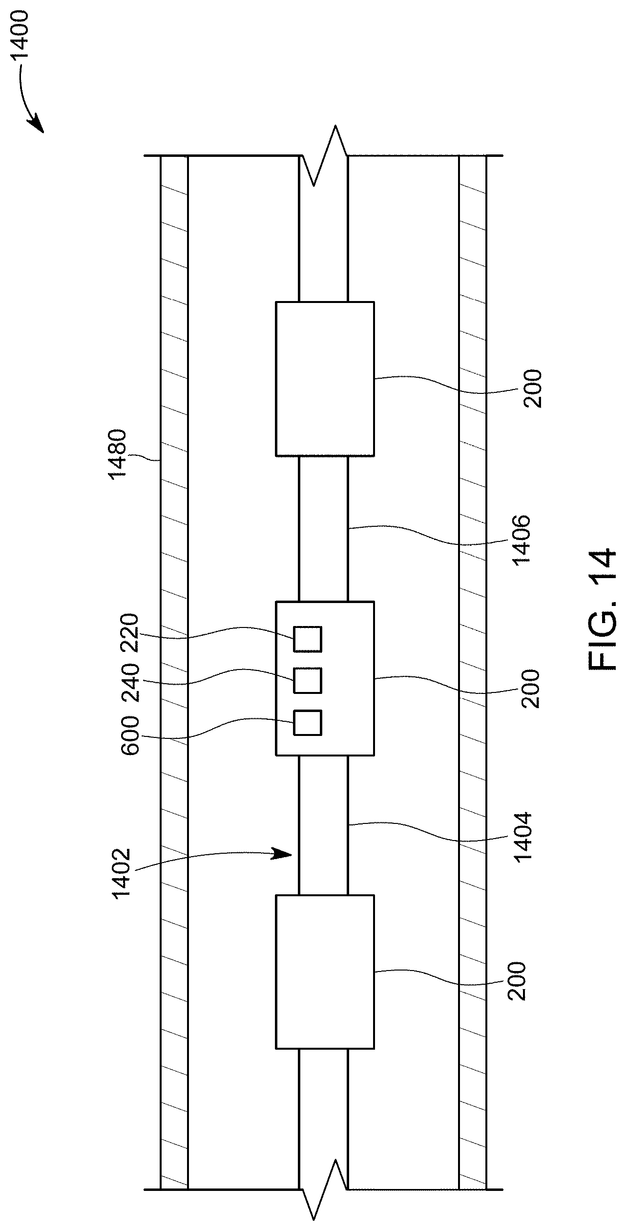
[0027] FIG. 14 illustrates plural downhole tools lowered into a downhole and having corresponding electronic time delays; and
[0028] FIG. 15 illustrates a toe valve having an electronic time delay and a mechanical time delay.
DETAILED DESCRIPTION
[0029] The following description of the embodiments refers to the accompanying drawings. The same reference numbers in different drawings identify the same or similar elements. The following detailed description does not limit the invention. Instead, the scope of the invention is defined by the appended claims. The following embodiments are discussed, for simplicity, with regard to a toe valve placed in a casing string. However, the embodiments discussed herein are also applicable to other oil and gas related devices that are pressure responsive, for example, a setting tool.
[0030] Reference throughout the specification to "one embodiment" or "an embodiment" means that a particular feature, structure or characteristic described in connection with an embodiment is included in at least one embodiment of the subject matter disclosed. Thus, the appearance of the phrases "in one embodiment" or "in an embodiment" in various places throughout the specification is not necessarily referring to the same embodiment. Further, the particular features, structures or characteristics may be combined in any suitable manner in one or more embodiments.
[0031] According to an embodiment, there is a downhole tool that has a sliding element, for example, a piston or a sleeve. The sliding element is initially in a first state (for example, closed). The downhole tool further includes a pressure responsive switch and an electronic valve. The pressure responsive switch may be activated by a given pressure inside the well. A switch-valve assembly that includes the switch has an electronic block which, after being activated, implements a desired time delay. After that time delay, the switch electronically instructs an electronic valve to open, to allow the high pressure from inside the casing to activate the sliding element. In this way, the sliding element moves to a second state (for example, opened). The time delay implemented by each electronic block is flexible, i.e., each tool in the tubing string may be configured to have a different time delay. The time delay may be easily changed at the surface, before lowering the tool into the well. The electronic block may be further configured to reset the time delay and/or cancel the time delay. Specific implementations of this switch-valve assembly are now discussed with regard to the figures.
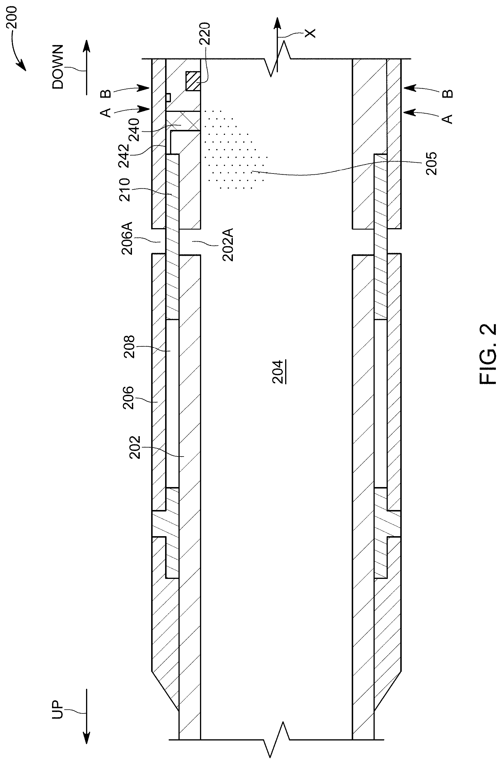
[0032] The following embodiments are discussed, for simplicity, for a toe valve. However, one skilled in the art, based on these teachings, would know how to implement the novel concepts to a setting tool or other tools that need to change from a first state to a second state. FIG. 2 shows a toe valve 200 that can be interconnected to a casing string. Note that the ends of the toe valve 200 shown in FIG. 2 are omitted as they can be identical to the ends of the toe valve 100 shown in FIGS. 1A and 1B. Different from the toe valve 100, the toe valve 200 does not have the low pressure chamber 34 and the hydraulic restrictor 22. These features are replaced by a switch 220 and an electronic valve 240.
[0033] FIG. 2 shows the toe valve having a mandrel 202 (also called a housing) that defines a bore 204. A cover 206 is attached, on the outside, to the mandrel 202, so that a sleeve chamber 208 is formed between the mandrel and the cover. A sleeve 210 is placed in the sleeve chamber 208 and is configured to slide from one end of the chamber to another one. FIG. 2 shows the sleeve 210 fluidly insulating the ports 206A formed in the cover 206, from the ports 202A, formed into the mandrel 202. However, when the sleeve 210 moves to the upstream end of the sleeve chamber (the upstream and downstream directions are indicated by corresponding arrows), fluid communication is established between these ports. This means that a fracturing fluid from the bore 204 may be pumped into the formation outside the well or the oil from the formation may flow into the bore. Note that the terms upstream and downstream are well defined in this context, as the upstream direction points to a head of a well and the downstream direction points to a toe of the well, irrespective of whether the well is horizontal, vertical or deviated.
[0034] In this embodiment, there is no other chamber or metering device for slowing down a movement of the sleeve in the sleeve chamber, different from the device discussed above with regard to FIGS. 1A and 1B. For this embodiment, there is an electronic valve 240 that has fluid access to the bore 204, and also fluidly communicates, via a passage 242, with the downstream end of the sleeve 210. The electronic valve 240 is set to be closed, i.e., does not allow a fluid 205 from the bore 204 to pass the valve to the passage 242. The electronic valve is electrically connected to the pressure responsive switch 220. When the switch 220 sends a signal to the electronic valve 240, the electronic valve 240 opens up and allows the fluid 205 to pass through the valve, and enter into the passage 242, and then move the sleeve 210 upstream, until fluid communication is established between the ports 202A and 206A.
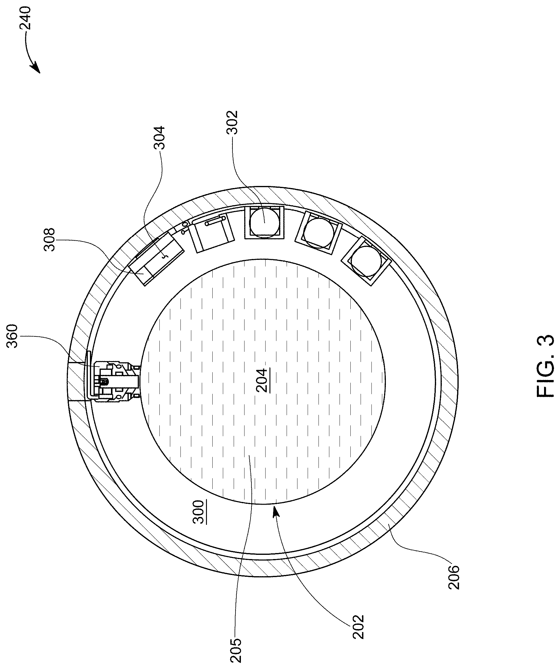
[0035] An example of an electronic valve 240 is now discussed with regard to FIGS. 3 and 4. FIG. 3 is a section A-A through the toe valve 200 that shows the electronic valve 240. In this figure, it is shown that various electronic modules may be placed in an empty pocket 300, formed in the body of the inner mandrel 202. Some of the electronic modules include a power source 302 (for example, a dry cell), a microprocessor 304, and a dump valve 360. The microprocessor 304 may be programmed in software or hardwired to have a timer 308, which is configured to have a given count down value, for example, 30 minutes. Other values are possible.
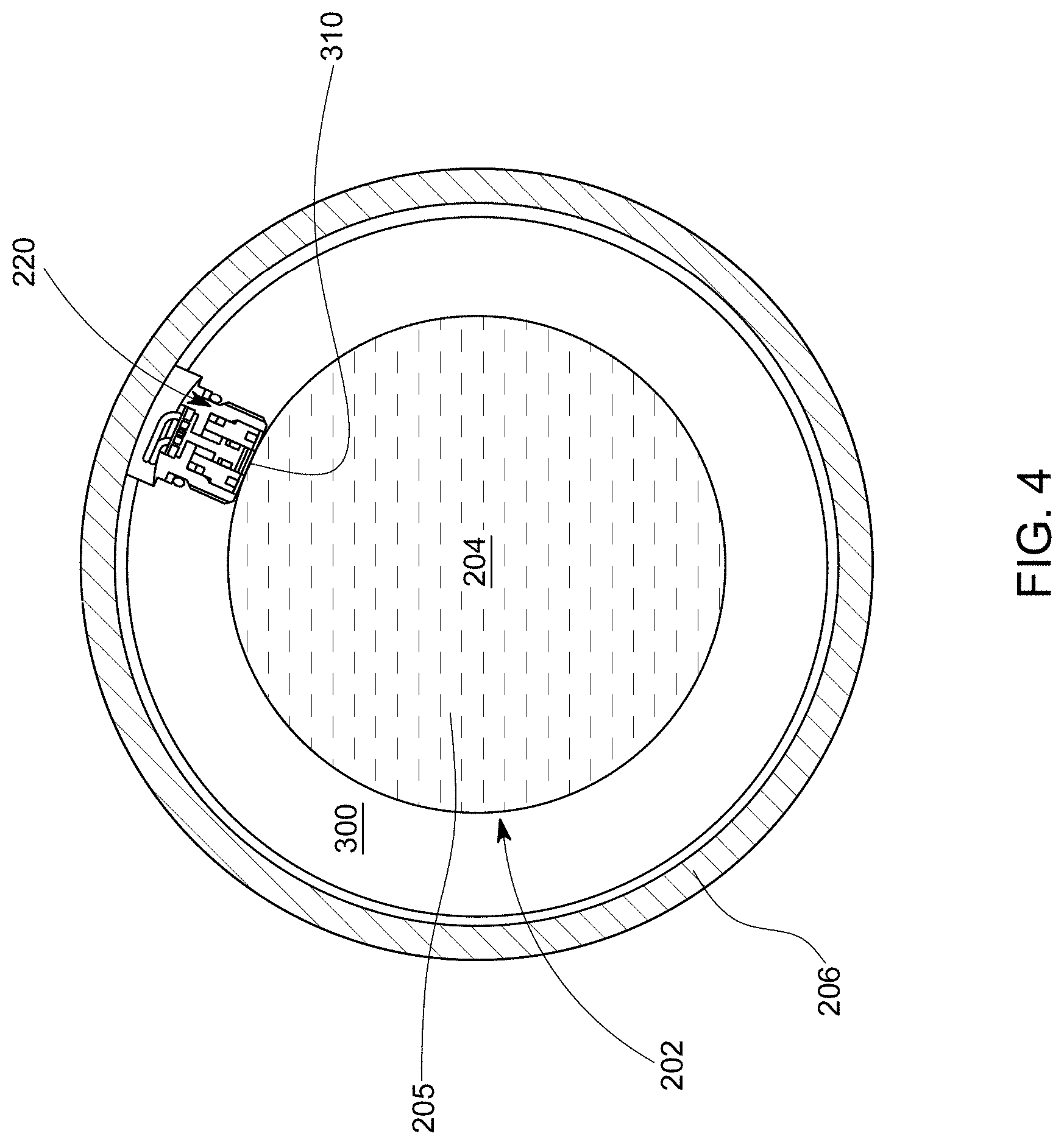
[0036] FIG. 4 is a section B-B through the toe valve 200 that shows the switch 220 placed in the same (or a different) pocket 300 of the mandrel 202. In both figures, the cover 206 is also shown. While FIG. 2 suggests that the switch 220 and the electronic valve 240 are not in the same cross-section of the mandrel, which is also illustrated in FIGS. 3 and 4, in one application it is possible to have them located in the same cross-section.
[0037] The switch 220 may have a burst disc 310 that is directly exposed to the pressure of the fluid 205 present in the bore 204, as shown in FIG. 4. The switch 220 is configured to activate the electronics inside the pocket 300, by providing power from the power source 302 to the other components. Note that this switch prevents draining the power source before the electronics are really necessary to be used to open the dump valve 360. Disc 310 can be broken by the fluid inside the bore 204 when its pressure is increased over the rated breaking pressure of the disk.
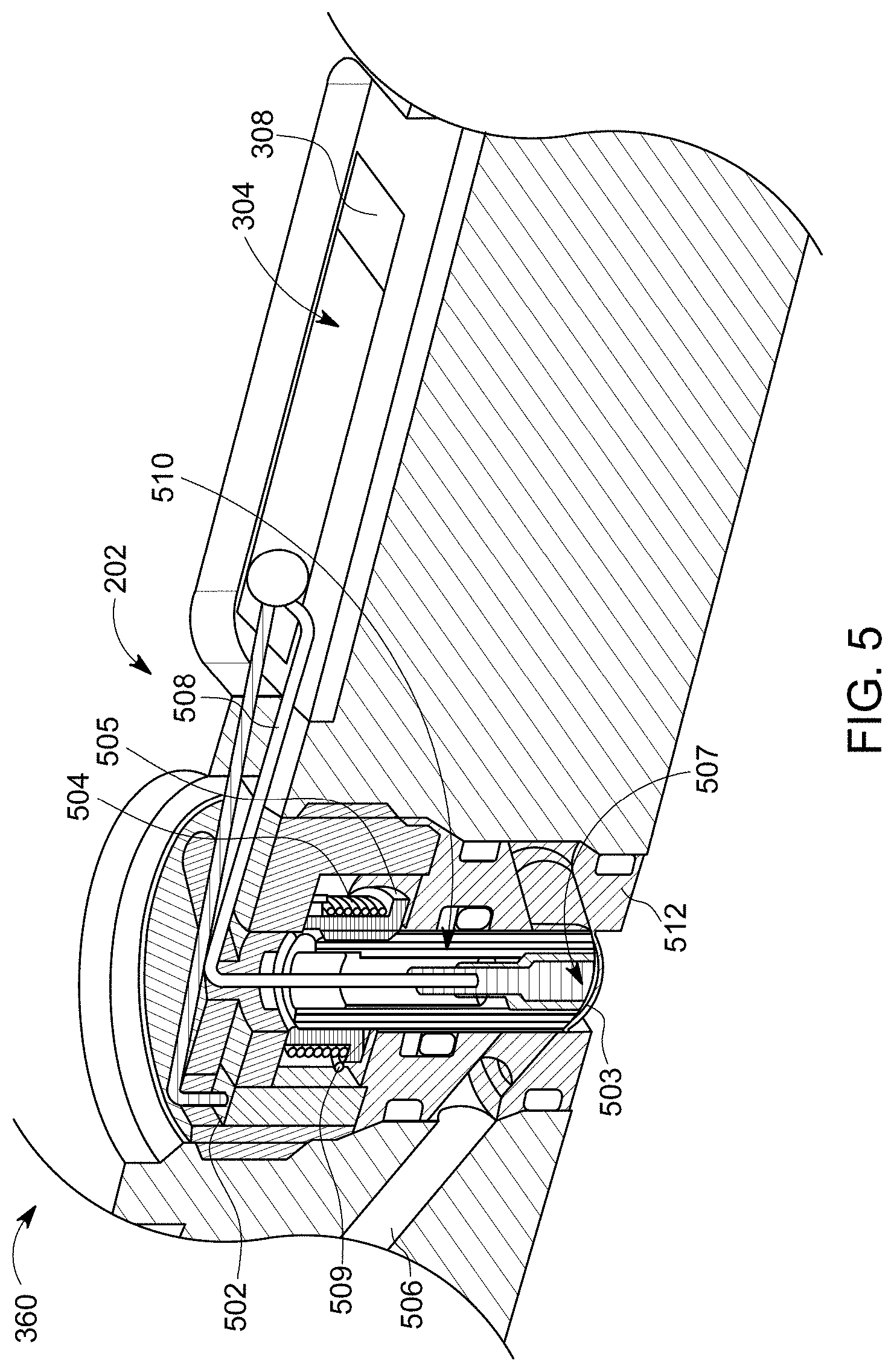
[0038] The dump valve 360 shown in FIG. 3 may be implemented in various ways. For example, FIG. 5 shows one possible configuration of the dump valve, that includes a fusible link 502 electrically connected to the processor 304, a split spool device 505, and a spring 504 surrounding the spool. The electrical connection of the fusible link to the processor is not shown. The split spool device 505 has a center pin assembly 510 held in place in a restrained position by the spool, and the spring 504 surrounding the spool. The timer 308 in the processor 304 may be actuated by the switch 220. After elapse of a predetermined time delay, set in the timer 308 by the operator before lowering the tool downhole, the timer generates a signal to initiate burning of the fusible link 502. The fusible link, which is mechanically restraining the spring 504, ruptures, thereby breaking the restraining connection 509 between the fusible link 502 and the spring 504. As a result, the center pin 510 travels upwards along with plunger 507 causing the rupture disk membrane 503 of rupture disk 512 to deflect upward and burst thereby opening the port 506 of the sliding valve to permit fluid flow to passage 242 (shown in FIG. 2). Of course, in another embodiment, the bursting of the rupture disk can be used to activate an entirely different activity in a downhole tool. In one application, the dump valve 360 may be implemented as a solenoid control valve or other types of known electronic valves.
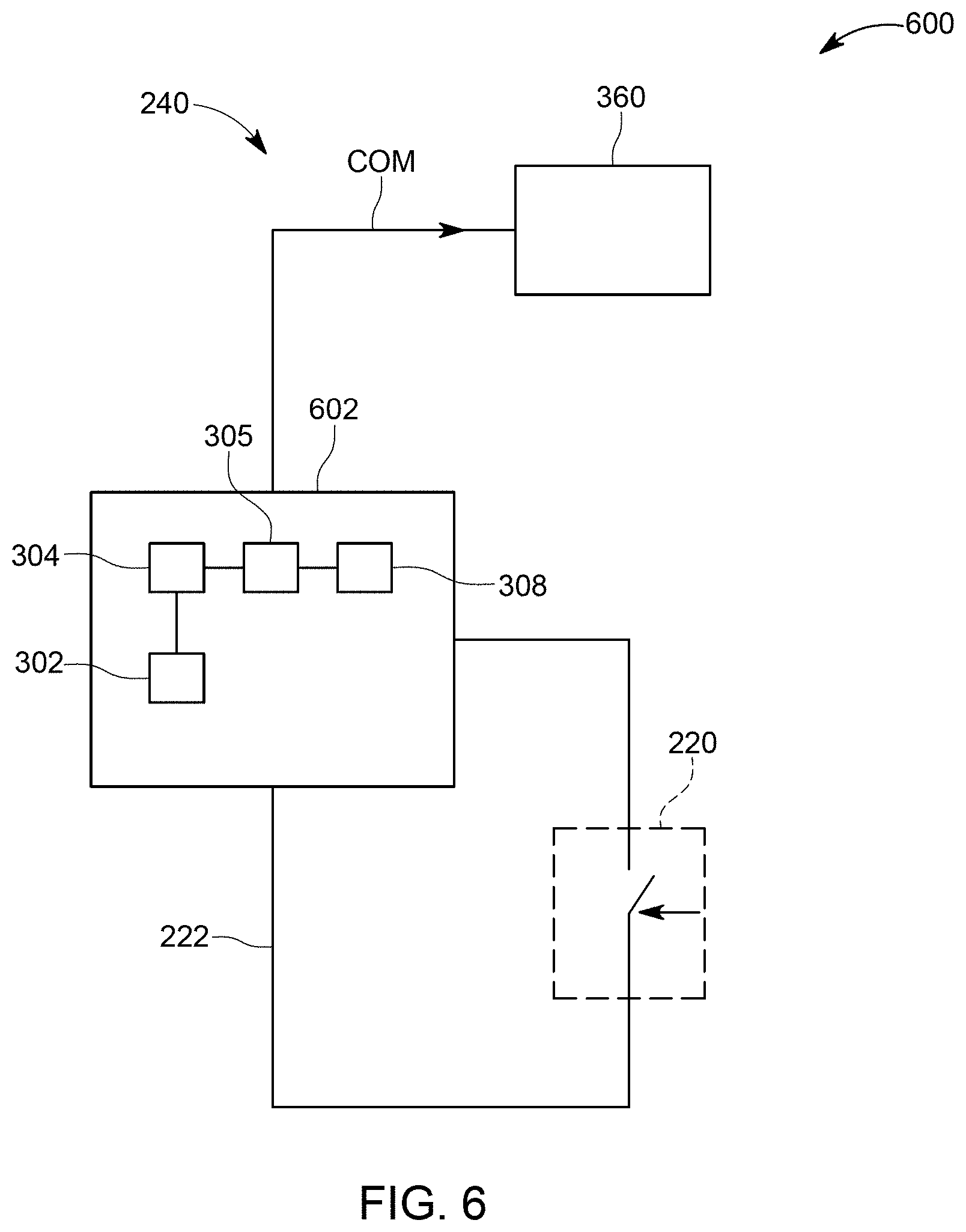
[0039] The possible implementations of the pressure responsive switch 220 are now discussed. In one embodiment, as illustrated in FIG. 6, the switch 220 is a pressure switch that closes an electrical circuit (represented by wires 222) for activating the processor 304. The switch 220, the electronic valve 240, and an associated electronic block 602 are referred to herein as a switch-valve assembly 600. Note that processor 304 and power source 302 were shown in FIG. 3 as being associated with electronic valve 240. This does not mean that these elements have to be part of the electronic valve 240. They may or may not be part of the electronic valve. When the switch 220 closes due to the fact that the fluid pressure inside the casing increases over a set value, an electrical connection is established between the power source 302 and the processor 304 and thus, the electronic block 602 is energized. At this time the electrical circuits in the processor 304 are activated and one or more software instructions, stored in a memory 305 associated with the processor 304, are executed. The software instructions may manage a timer 308 that was programmed by the operator of the toe valve to count down a certain time. This time may take any value between 1 and 1,200 minutes. This value can be electronically changed at any time before the toe valve is deployed in the well. If electrical wires or other communication medium is provided inside the casing, it is possible to change this time even after the toe valve has been deployed inside the well.
[0040] After the timer 308 counts down the set time, it sends a command COM to the dump valve 360 to open. When this happens, the pressured fluid 205 inside the casing 204 is allowed to pass the electronic valve 240 and to arrive at passage 242. The pressured fluid now exerts a casing pressure on the downstream end of the sleeve 210 and starts moving the sleeve 210 inside the sleeve chamber 208, until the ports 202A and 206A are in fluid communication. While the embodiment of FIG. 6 uses the switch 220 with the toe valve 200, as previously noted, it is possible to use the switch with a setting tool or any other downhole tool. The various electronic elements 302, 304, 306, and 308 shown in FIG. 6 may be part of the electronic valve 240, but they also may be implemented as a separate electronic block 602. In other words, it is possible to have three independent modules, the switch 220, the electronic valve 240, and the electronic block 602 and these three blocks may be added as a switch-valve assembly 600 to a downhole tool. Although the three modules are independent modules, they are electrically linked to each other and functionally work in tandem with each other.
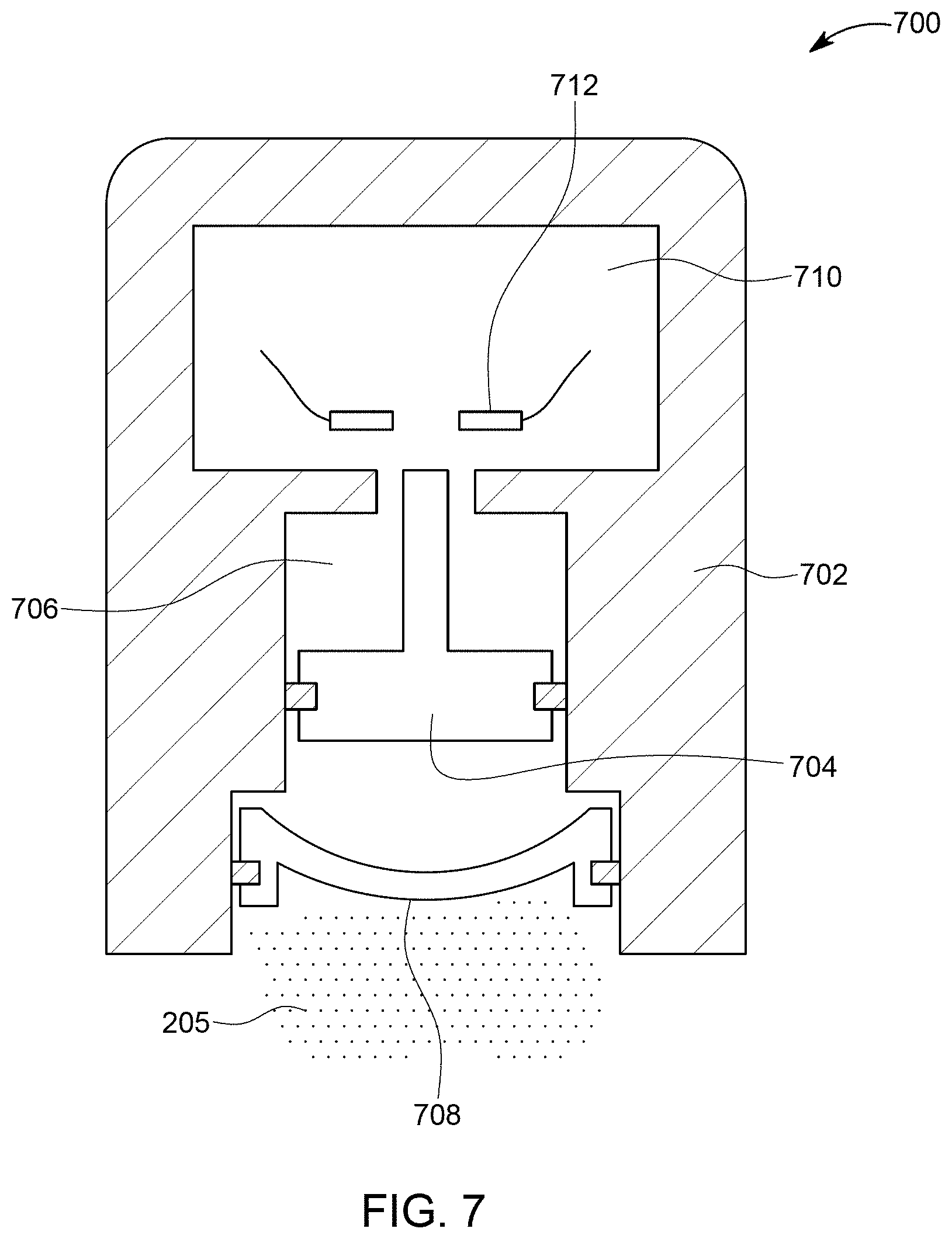
[0041] The switch 220 may be any known pressure sensitive switch. For example, as shown in FIG. 7, a switch 700 may have a housing 702 that holds a moving piston 704. The moving piston 704 is located in a chamber 706 that is closed by a burst disc 708. The burst disc 708 corresponds to disc 310 in FIG. 4. This disc is exposed to the fluid in the casing. However, the disc 708 is sealing the chamber 706 so that no fluid enters inside the chamber. Another chamber 710 (electrical chamber) houses an open electrical circuit 712. When the pressure inside the casing is increased over a set value, the pressure of the fluid 205 breaks the disc 708, and pushes the piston 704 inside the electrical chamber 710, so that the electrical circuit 712 is closed, which results in energizing the electronic block 602. Note that if this type of switch 220/700 is implemented, and multiple tools in the well bore are equipped with such switches, it is possible that the discs 708 for these switches are configured to break at different pressures, so that not all the tools are activated at the same time. Even if the discs break at the same time, the timers 308 of the tools may be programmed to have specific times for each tool, so that not all the tools open at the same time. In one embodiment, groups of tools may be configured to have the same time set for the timers or to have their discs break at the same pressure.
[0042] A method for using such a switch is now discussed with regard to FIG. 8. In step 800, a downhole tool (for example, a toe valve) is attached to a casing string and lowered into the well. In step 802, the pressure inside the casing is increased over a threshold value, so that the switch 700 associated with tool is activated as its disc is broken. In step 804, the electronic block 602 are becoming alive, as electrical power is supplied from the power source 302 to the other elements of the electronic block 602. The timer 308 is now triggered and starts to count down the set time in step 806. At the end of the set time, the electronic block 602 sends a command COM in step 808 to the valve 240 of the tool associated with the switch, e.g., the toe valve 200. The command actuates the electronic valve 240, which makes the pressured fluid inside the casing to exert a force on the sleeve 210. In step 810, the tool is actuated, i.e., the sleeve has moved from the closed position to the open position so that a fluid communication is established between the inside of the tool and its outside.
[0043] In another implementation, as illustrated in FIG. 9, the switch 220 is configured to be resettable. FIG. 9 shows the switch 220 being configured to close the circuit when a bore pressure is larger than a given threshold, similar to the switch 220 shown in FIG. 6. However, the switch 220 in FIG. 9 can also be re-set, as illustrated by the arrow inside the switch. More specifically, FIG. 10 shows one possible implementation of such a resettable switch/2201000. The structure of the switch 1000 is similar to the structure of the switch 700, except that a bias mechanism 1020 (e.g., a spring) is placed inside the chamber 706, to bias the piston 704 toward the bore 204. Another difference relative to the switch 700 is that there is no disc 708, so that the well fluid acts directly on the piston 704. This means that when the fluid pressure Pf increases beyond an equilibrium force applied by the bias mechanism 1020, the piston 704 moves toward the electrical chamber 710 and closes the contact 712. However, if the pressure inside the casing is lowered, the bias mechanism 1020 pushes away the piston 704, and opens the electrical contacts 712. Thus, by controlling the fluid pressure inside the casing, it is possible to switch on and off the switch 1000.
[0044] If the switch 220/1000 is switched off, then the electrical power from the power source 302 in FIG. 9 is cut from the processor 304, memory 305, and timer 308, and the countdown operation of the timer 308 is stopped. The processor 304 may be configured to reset the timer the next time that power is provided, i.e., when the switch 1000 energizes the electronic block 602 the next time. For this implementation, it is possible that at a depth in the well of 10,000 feet, the hydrostatic pressure might be about 5,000 psi. If the pumping pressure at the surface is raised by 3,000 psi, the bottom hole pressure would be 8,000 psi. If the set pressure for closing the contacts 712 is set at 7,000 psi and the pressure to open the contacts is set at 6,000 psi, by increasing the pressure above 2,000 psi and then reducing the surface pressure less than 1,000 psi, the switch will toggle On then Off. A method for using this configuration would have similar steps as the method illustrated in FIG. 8, except that an additional step of lowering the pressure inside the casing for resetting the timer is added.
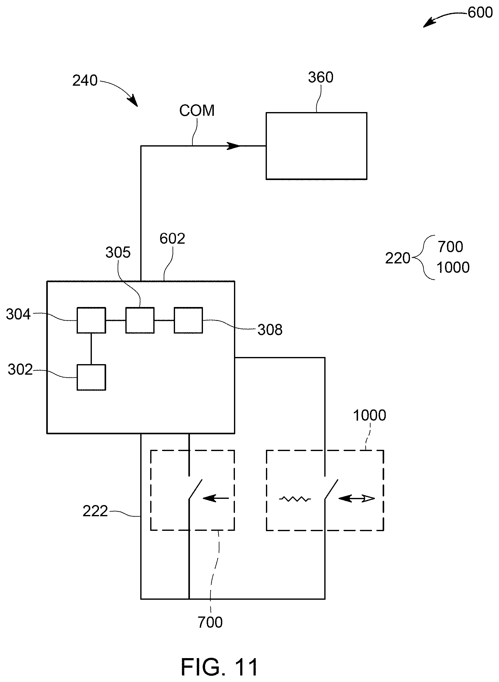
[0045] In still another implementation, as illustrated in FIG. 11, it is possible to implement both switches 700 and 1100 as the pressure activated switch 220. In this way, it is possible to use the switch 700 to electrically energize the electronics block 602 and/or other elements (when a first threshold pressure breaks the disc of the switch 700). However, the timer 308 would not be started when electrical power is supplied to the electronic block 602 as in the previous embodiments. For this action to happen, it would be necessary that the pressure in the casing becomes larger than a second threshold pressure. When this happens, the switch 1000 is activated and this action triggers the timer 308 to start the countdown.
[0046] In one application, as illustrated in FIG. 12, the switch 1000 is replaced by a pressure transducer 1210. The pressure transducer 1210 is capable of measuring a pressure inside the casing. A corresponding signal is transmitted from the pressure transducer 1210 to the processor 304, after the switch 700 has energized the electronics block 602. The processor compares the measured pressure with a threshold pressure stored in the memory 305, and determines when to activate the timer 308. The threshold pressure can be modified just before the toe valve is lowered into the well or even after the toe valve has been lowered into the well, if a communication medium is provided. If such a communication medium is provided, a transceiver 1220 may be added to the electronic block 602 for communicating with a global controller 1230 that is located at the head of the well. In one embodiment, the transceiver 1220 is configured to be wired to the surface and exchange electromagnetic signals with the global controller 1230. However, in one application, the transceiver is a sound modem that can receive and transmit sound signals, through the fluid present in the casing. Those skilled in the art, based on the teachings presented here, would be able to use other mediums and/or ways for communication.
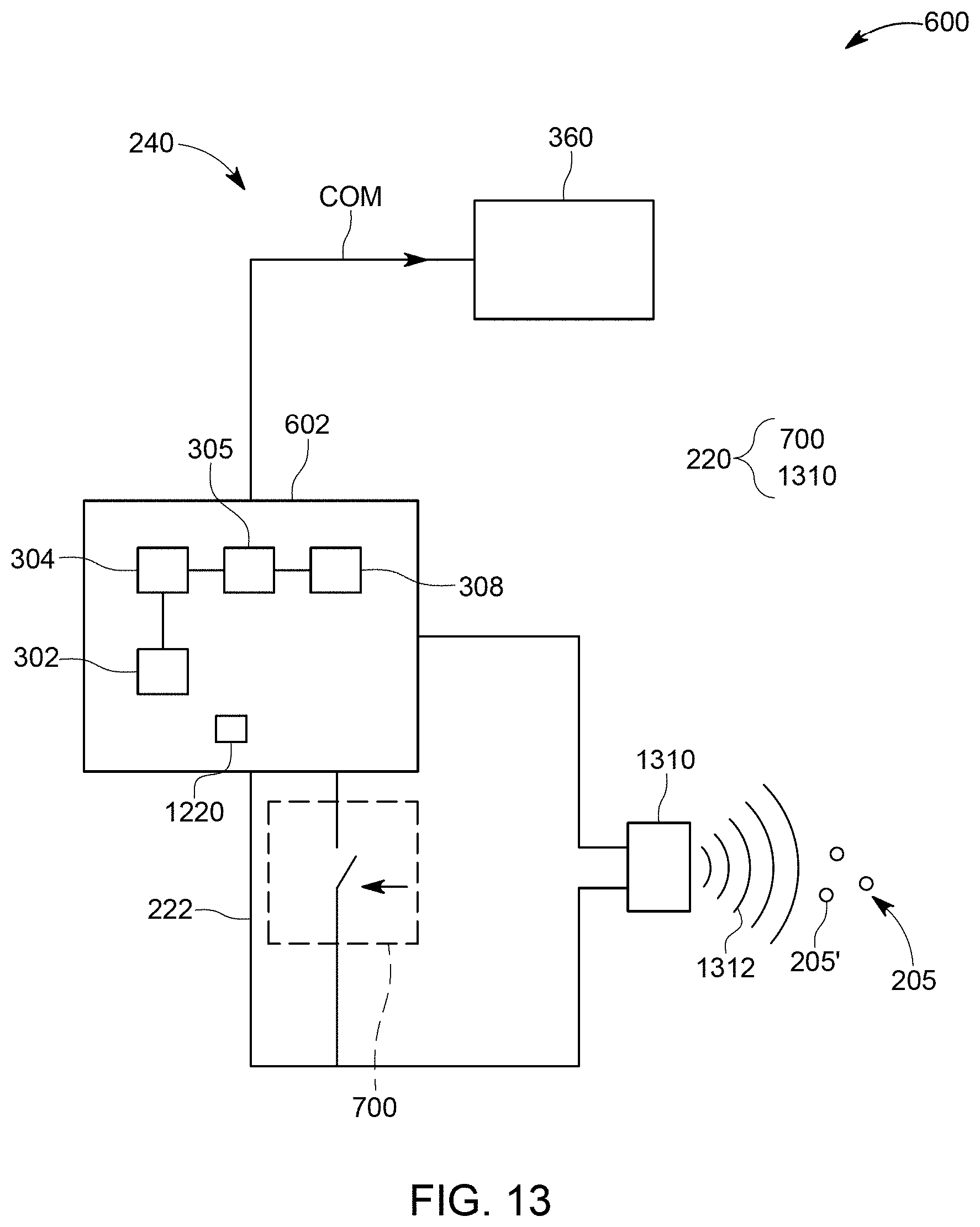
[0047] In still another embodiment, as illustrated in FIG. 13, it is possible to use a velocity transducer 1310 instead of the switch 1000 or pressure transducer 1210. The velocity transducer is configured to measure a velocity v of a particle 205' of the fluid 205 inside the casing. Any type of velocity transducer may be used. In this embodiment, an ultrasonic transducer is used. The velocity transducer 1310 would send an acoustic pulse 1312 that would reflect off of particles 205' of the fluid 205. The time of flight, or doppler shift would determine the velocity of these particles. As the fluid 205 is pumped inside the casing, particles 205' such as sand would be seen with the transducer. By changing the velocity and/or reversing the velocity direction, a command may be send to the electronic box 602. This command would be used to control various events (for example, starting the timer 308) in the same manner as explained in the previous embodiments. The switch 700 is used in this embodiment to energize the electronic block 602.
[0048] In one application, the velocity transducer may be replaced by a radar system or any other system that can measure a movement of the fluid, or another characteristic of the fluid, for example, its density, chemical composition, etc. Then, in that application, the density or chemical composition may be changed from the surface in order to send a command to the electronic block 602.
[0049] Having the electronic valve 240 implemented with a switch 220 as discussed in the previous embodiments, into a downhole tool, in effect achieves down-link communication. An example might be using the pressure transducer of FIG. 12 and monitoring the inner casing pressure. Before being deployed into the well, the electronic block of each tool could be programmed to each have a unique address. Then, after the switch 700 is activated, the pressure transducer 1210 would listen for its pattern. When a pattern is heard, the processor 304 determines whether that pattern belongs to this sensor. If the result of this determination is yes, then the instructions stored in the memory 305 for this particular tool are executed so that a desired event or events is achieved by this tool. A pattern might be as simple as: low pressure for 10 minutes, which might re-set all of the observations. Then increase the pressure to a high pressure=2 minutes, low pressure=1 minute, high pressure=2 minutes, and again low pressure=1 minute. When this pattern is recorded by the pressure sensor 1310 and recognized by the processor 304, it could activate the tool associated with this processor. Another pattern, like high pressure=1 minute, low pressure=1 minute, high pressure=1 minute, and low pressure=1 minute could be used to control another tool. The pattern could be frequency based, or amplitude based, and any combination.
[0050] Although the embodiments discussed herein have considered the act of simply actuating the sleeve of a toe valve, each tool need not be limited to just one task. One or more tools could be designed to perform other operations in addition to, or instead of opening and closing a sleeve.
[0051] As illustrated in the embodiment of FIG. 14, plural tools 200 may be interconnected with a casing string 1402 and provided in a well 1480. In this example, a single tool 200 is connected between tubular pipes 1404 and 1406. The tool 200 may include a switch 220, an electronic valve 240, and an electronic block 602. The other tools 200 may be identical to this tool or not. Tool 200 may be a toe valve, a valve, or a setting tool. Each tool 200 may be configured to have a different countdown time of a corresponding timer, or different implementations for the switch 220.
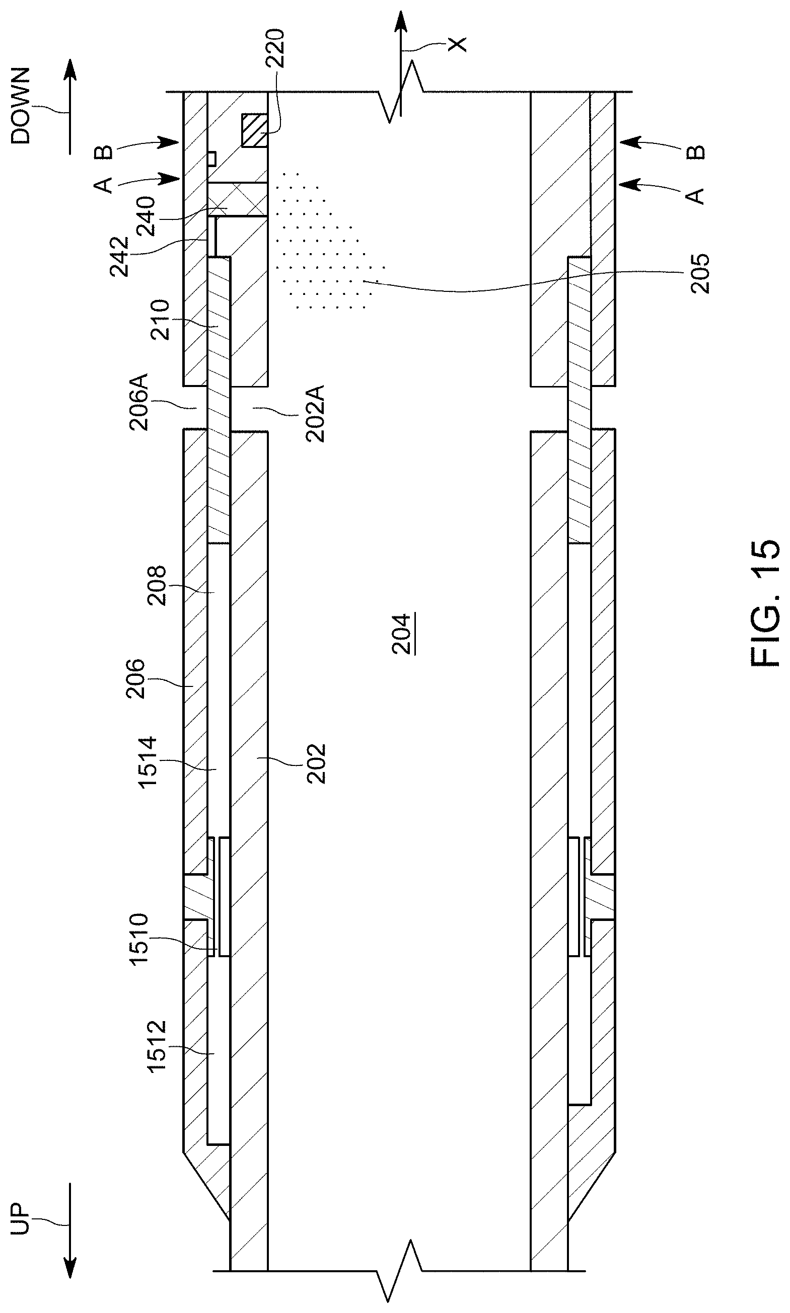
[0052] While the downhole tool 200 has been discussed herein as not including an additional metering device, it is also possible, as illustrated in FIG. 15, to combine the electronic valve 240 and the switch 220 with a hydraulically metering system as illustrated in FIG. 1B. In other words, as shown in FIG. 15, downhole tool 200 may be modified to have a narrow passage 1510 between the sleeve chamber 208 and a second chamber 1512. In this way, a fluid 1514, which is located in the sleeve chamber 208, is slowly pushed from the sleeve chamber to the second chamber when the sleeve 210 is opened. This achieves a controlled slow opening motion for the sleeve 210. The diameter of the passage 1510 dictates how slow the fluid 1514 moves from one chamber to another, i.e., how slow the sleeve 208 opens after the timer has counted down its set time.
[0053] The disclosed embodiments provide methods and systems for actuating a downhole tool with a desired time delay. It should be understood that this description is not intended to limit the invention. On the contrary, the exemplary embodiments are intended to cover alternatives, modifications and equivalents, which are included in the spirit and scope of the invention as defined by the appended claims. Further, in the detailed description of the exemplary embodiments, numerous specific details are set forth in order to provide a comprehensive understanding of the claimed invention. However, one skilled in the art would understand that various embodiments may be practiced without such specific details.
[0054] Although the features and elements of the present exemplary embodiments are described in the embodiments in particular combinations, each feature or element can be used alone without the other features and elements of the embodiments or in various combinations with or without other features and elements disclosed herein.
[0055] This written description uses examples of the subject matter disclosed to enable any person skilled in the art to practice the same, including making and using any devices or systems and performing any incorporated methods. The patentable scope of the subject matter is defined by the claims, and may include other examples that occur to those skilled in the art. Such other examples are intended to be within the scope of the claims.
* * * * *
D00000
D00001
D00002
D00003
D00004
D00005
D00006
D00007
D00008
D00009
D00010
D00011
D00012
D00013

D00014
D00015
D00016
XML
uspto.report is an independent third-party trademark research tool that is not affiliated, endorsed, or sponsored by the United States Patent and Trademark Office (USPTO) or any other governmental organization. The information provided by uspto.report is based on publicly available data at the time of writing and is intended for informational purposes only.
While we strive to provide accurate and up-to-date information, we do not guarantee the accuracy, completeness, reliability, or suitability of the information displayed on this site. The use of this site is at your own risk. Any reliance you place on such information is therefore strictly at your own risk.
All official trademark data, including owner information, should be verified by visiting the official USPTO website at www.uspto.gov. This site is not intended to replace professional legal advice and should not be used as a substitute for consulting with a legal professional who is knowledgeable about trademark law.