Concealed Air Vent Apparatus In Vehicle And A Method Thereof
KAKADE; Ritesh ; et al.
U.S. patent application number 16/980415 was filed with the patent office on 2021-01-07 for concealed air vent apparatus in vehicle and a method thereof. The applicant listed for this patent is MAHINDRA & MAHINDRA LIMITED. Invention is credited to Srinath JAYAN, Ritesh KAKADE, Prashant PANDEY.
| Application Number | 20210001693 16/980415 |
| Document ID | / |
| Family ID | |
| Filed Date | 2021-01-07 |


| United States Patent Application | 20210001693 |
| Kind Code | A1 |
| KAKADE; Ritesh ; et al. | January 7, 2021 |
CONCEALED AIR VENT APPARATUS IN VEHICLE AND A METHOD THEREOF
Abstract
Concealed air vent apparatus in a vehicle and a method thereof is provided. The apparatus includes an air vent casing, at least one air directing flap, at least one air diffusing flap, at least one closing flap, an air directing flap actuator, an air diffusing flap actuator and a closing flap actuator. The air diffusing flap actuator is adapted to move air diffusing flap to a diffused position in which a plurality of air diffusing portions of air diffusing flap is adapted to facilitate uniform distribution of air to an occupant compartment. The closing flap actuator is adapted to move closing flap between an open position in which closing flap is adapted to allow air flow to the occupant compartment, and a closed position in which closing flap is adapted to restrict air flow to the occupant compartment.
| Inventors: | KAKADE; Ritesh; (Tamil Nadu, IN) ; PANDEY; Prashant; (Tamil Nadu, IN) ; JAYAN; Srinath; (Tamil Nadu, IN) | ||||||||||
| Applicant: |
|
||||||||||
|---|---|---|---|---|---|---|---|---|---|---|---|
| Appl. No.: | 16/980415 | ||||||||||
| Filed: | November 29, 2018 | ||||||||||
| PCT Filed: | November 29, 2018 | ||||||||||
| PCT NO: | PCT/IN2018/050798 | ||||||||||
| 371 Date: | September 13, 2020 |
| Current U.S. Class: | 1/1 |
| International Class: | B60H 1/34 20060101 B60H001/34; B60H 1/00 20060101 B60H001/00 |
Foreign Application Data
| Date | Code | Application Number |
|---|---|---|
| Mar 13, 2018 | IN | 201841009253 |
Claims
1. A concealed air vent apparatus 100 for a vehicle, said apparatus 100 comprising: at least one air diffusing flap 106 having a plurality of air diffusing portions 106a; at least one closing flap 108; an air diffusing flap actuator 112 adapted to be coupled to said air diffusing flap 106; and a closing flap actuator 114 adapted to be coupled to said closing flap 108, wherein said air diffusing flap actuator 112 is configured to receive input from a controller unit and accordingly moves said air diffusing flap 106 to a diffused position in which the plurality of air diffusing portions 106a of said air diffusing flap 106 is adapted to facilitate uniform distribution of air to an occupant compartment of the vehicle; and said closing flap actuator 114 is configured to receive input from the controller unit and accordingly moves said closing flap 108 between an open position in which said closing flap 108 is adapted to allow air flow to the occupant compartment, and a closed position in which said closing flap 108 is adapted to restrict air flow to the occupant compartment.
2. The apparatus 100 as claimed in claim 1, wherein at least a portion of each of said air diffusing portion 106a of said air diffusing flap 106 substantially defines at least a cone shape configuration.
3. The apparatus 100 as claimed in claim 2, wherein said air diffusing flap 106 and said closing flap 108 are co-planar to each other.
4. The apparatus 100 as claimed in claim 3 comprising at least one air directing flap 104 adapted to direct the air flow in selective directions in occupant compartment according to user requirement.
5. The apparatus 100 as claimed in claim 4 comprising an air directing flap actuator 110 configured to receive input from the controller unit and accordingly moves said air directing flap 104 to a plurality of air directing positions according to user requirement.
6. The apparatus 100 as claimed in claim 5, wherein said air directing flap 104 is disposed opposite to said air diffusing flap 106 and said closing flap 108.
7. The apparatus 100 as claimed in claim 6 wherein said air directing flap 104 is adapted to be moved manually through a control knob arrangement to direct the air flow in selective directions in occupant compartment according to user requirement.
8. The apparatus 100 as claimed in claim 1, wherein said air directing flap actuator 110, said air diffusing flap actuator 112 and said closing flap actuator 114 are at least electric motors.
9. The apparatus 100 as claimed in claim 1, wherein the controller unit is configured to receive inputs from at least one of an user interface unit and an electronic device, and accordingly actuates at least one of said air directing flap actuator 110, said air diffusing flap actuator 112 and said closing flap actuator 114 based on the user requirement.
10. The apparatus 100 as claimed in claim 1 is configured to be concealed in at least an instrumental panel of the vehicle.
11. A method 200 for providing and operating an air vent apparatus 100 in a vehicle, said method 200 comprising: providing the air vent apparatus 100 with at least one air directing flap 104, at least one air diffusing flap 106, at least one closing flap 108, an air diffusing flap actuator 112 and a closing flap actuator 114; concealing the air vent apparatus 100 in a vehicular structure; directing the air flow in selective directions in occupant compartment through the air directing flap 104 according to user requirement; diffusing uniformly the air flow in an occupant compartment through the air diffusing flap 106 by moving the air diffusing flap 106 to an air diffusing position through the air diffusing flap actuator 112 based on an input from a controller unit to the air diffusing flap actuator 112; and restricting air flow to the occupant compartment by moving the closing flap 108 to a closed position through the closed flap actuator 114 based on an input from the controller unit to the closed flap actuator 114.
12. The method 200 as claimed in claim 9 comprising providing user defined inputs to the controller unit through at least one of an user interface unit and an electronic device, and accordingly the controller unit actuates at least one of the air directing flap actuator 110, the air diffusing flap actuator 112 and the closing flap actuator 114 based on the user requirement.
Description
CROSS REFERENCE TO RELATED APPLICATION
[0001] This application is based on and derives the benefit of Indian Provisional Application 201841009253 filed on 13 Mar. 2018, the contents of which are incorporated herein by reference.
TECHNICAL FIELD
[0002] The embodiments herein relate to a concealed air vent apparatus for a HVAC system in a vehicle, and a method for providing and operating the concealed air vent apparatus in the vehicle.
BACKGROUND
[0003] Generally, heating, ventilation and air conditioning system (hereinafter called as HVAC system) in a vehicle is used to clean, cool, warm, regulate, ventilate and dehumidify the air entering a cabin of the vehicle thereby enhancing the comfort level of occupants in the vehicle. Typically, HVAC system comprises an air conditioner unit for cooling or conditioning the air entering the cabin of the vehicle and a cabin heater for warming the air entering the cabin. In conventional vehicles, air vents are provided to a dashboard (instrumental panel) at a fixed location and is visible to the occupants in the vehicle. The air vents are controlled mechanically through knobs which are operated by the occupants to receive the air towards corresponding occupant or to the desired location of the occupant by changing the angle and position of flaps provided on air vents. The air ducts are connected between the air vents and an air blower of the HVAC system to provide cool air or warm air to the cabin. Usually, the passenger and the driver tend to adjust two or three air vents to receive the cool air or warm air that is discharged towards them. The air vents should be located towards the respective occupant seating location or to the desired location of the occupant, for better discharging of air. However, packaging and arranging the air vents to corresponding occupant seating location or the desired location of the corresponding occupants is complex and is one of the challenges posed to the original equipment manufacturers (OEM). Further, the air from the air vents is not uniformly distributed in the occupant compartment.
[0004] Therefore, there exists a need for a concealed air vent apparatus for a HVAC system in a vehicle, which obviates the aforementioned drawbacks. Further, there exists a need for a method for providing and operating a concealed air vent apparatus in a vehicle.
OBJECTS
[0005] The principal object of an embodiment is to provide a concealed air vent apparatus for a HVAC system in a vehicle.
[0006] Another object of an embodiment is to provide a method for providing and operating a concealed air vent apparatus in a vehicle.
[0007] Another object of an embodiment of this invention is to provide a concealed multimode air vent apparatus for a HVAC system in a vehicle, which enhances comfort of the occupants in the vehicle.
[0008] Another object of an embodiment of this invention is to provide a concealed air vent apparatus for a HVAC system in a vehicle, in which air vent controls are operated electronically through a user interface (UI) unit.
[0009] These and other objects of the embodiments herein will be better appreciated and understood when considered in conjunction with the following description and the accompanying drawings. It should be understood, however, that the following descriptions, while indicating embodiments and numerous specific details thereof, are given by way of illustration and not of limitation. Many changes and modifications may be made within the scope of the embodiments herein without departing from the spirit thereof, and the embodiments herein include all such modifications.
BRIEF DESCRIPTION OF DRAWINGS
[0010] The embodiments of the invention are illustrated in the accompanying drawings, throughout which like reference letters indicate corresponding parts in the various figures. The embodiments herein will be better understood from the following description with reference to the drawings, in which:
[0011] FIG. 1 depicts a front view of the concealed air vent apparatus, where the apparatus is in an air directing mode, according to an embodiment of the invention as disclosed herein;
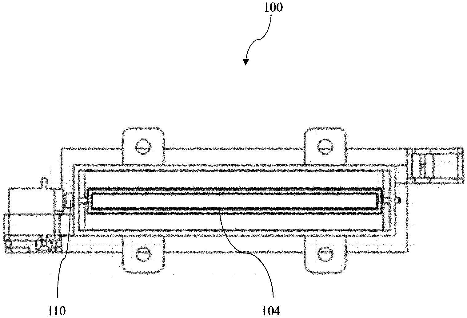
[0012] FIG. 2 depicts a top view of the concealed air vent apparatus, where an air diffusing flap is in an open position, according to an embodiment of the invention as disclosed herein;
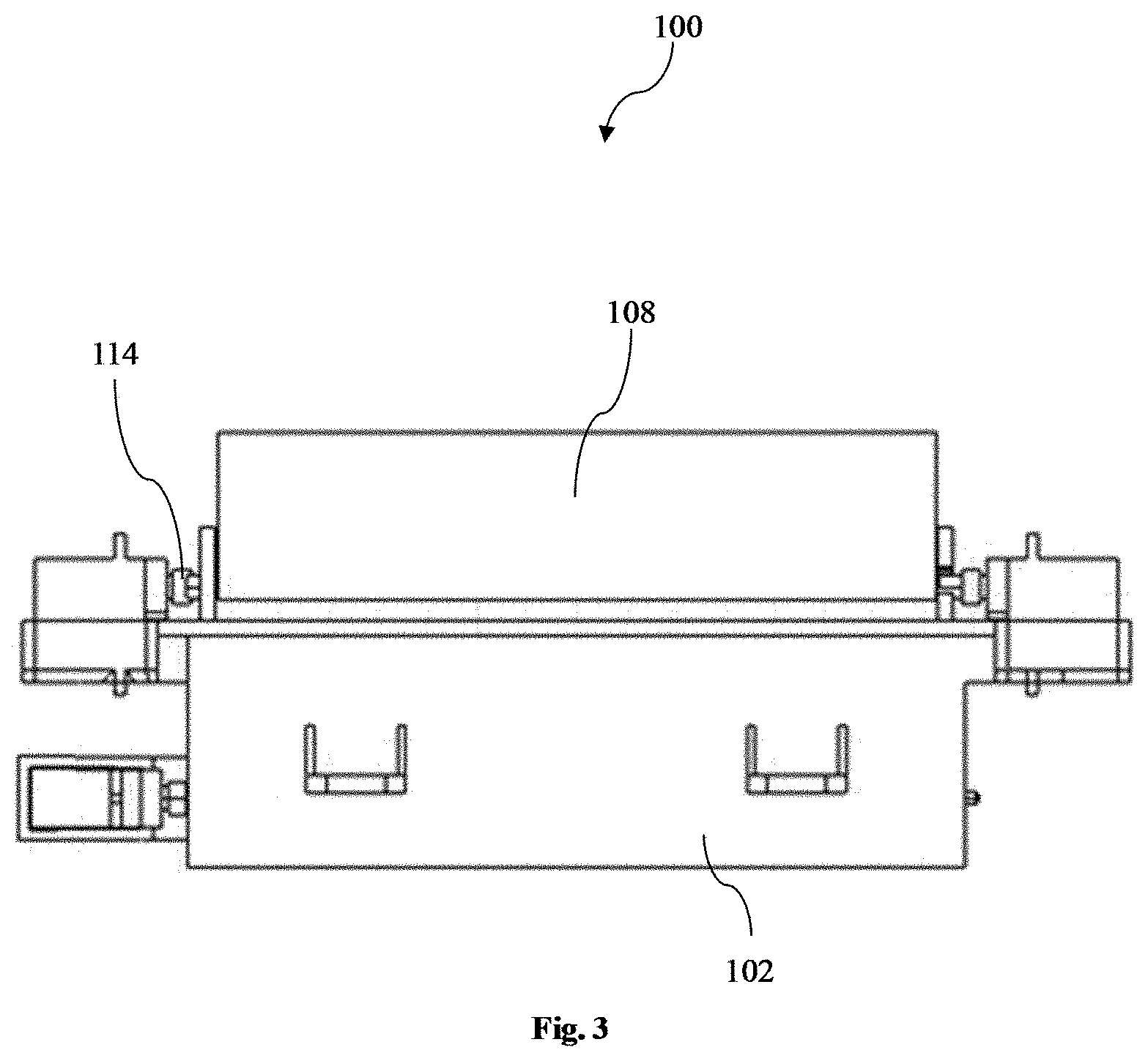
[0013] FIG. 3 depicts a top view of the concealed air vent apparatus, where a closing flap is in an open position, according to an embodiment of the invention as disclosed herein; and
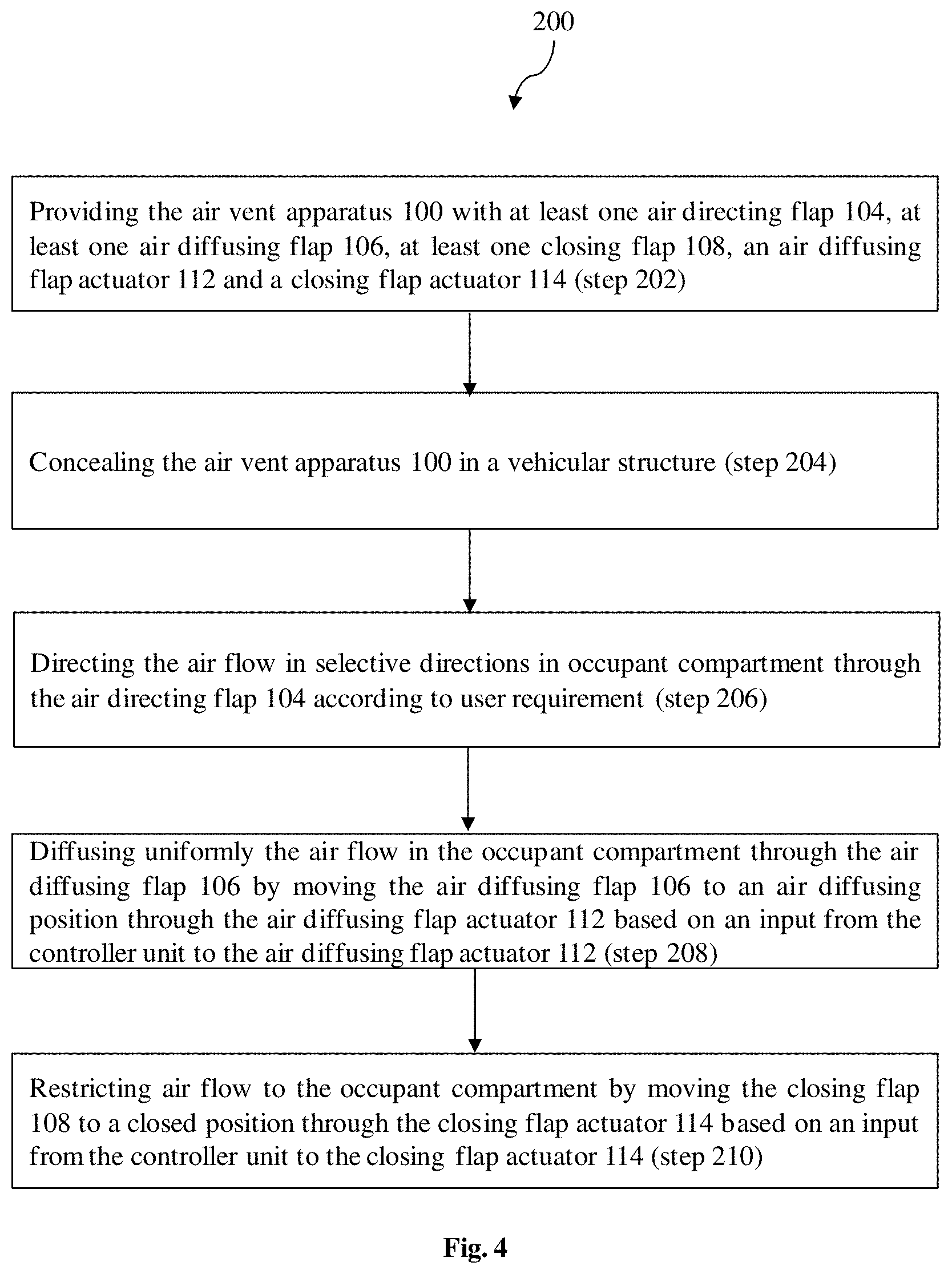
[0014] FIG. 4 depicts a flowchart showing the steps of a method for providing and operating a concealed air vent apparatus in a vehicle, according to an embodiment of the invention as disclosed herein.
DETAILED DESCRIPTION
[0015] The embodiments herein and the various features and advantageous details thereof are explained more fully with reference to the non-limiting embodiments that are illustrated in the accompanying drawings and detailed in the following description. Descriptions of well-known components and processing techniques are omitted so as to not unnecessarily obscure the embodiments herein. The examples used herein are intended merely to facilitate an understanding of ways in which the embodiments herein may be practiced and to further enable those of skill in the art to practice the embodiments herein. Accordingly, the examples should not be construed as limiting the scope of the embodiments herein.
[0016] The embodiments herein achieve a concealed air vent apparatus for a HVAC system in a vehicle. Further, embodiments herein achieve a method for providing and operating a concealed air vent apparatus in a vehicle. Referring now to the drawings, and more particularly to FIGS. 1 through 4, where similar reference characters denote corresponding features consistently throughout the figures, there are shown embodiments.
[0017] FIG. 1 depicts a front view of the concealed air vent apparatus 100, where the apparatus 100 is in an air directing mode, according to an embodiment of the invention as disclosed herein. In an embodiment, the air vent apparatus 100 is concealed in a vehicular structure. The air vent apparatus 100 is used to provide cool air or warm air to an occupant compartment of the vehicle and is not visible to the occupants in the vehicle. In an embodiment, the concealed air vent apparatus 100 includes an air vent casing 102, at least one air directing flap 104, at least one air diffusing flap 106, at least one closing flap 108, an air directing flap actuator 110, an air diffusing flap actuator 112 and a closing flap actuator 114. For the purpose of this description and ease of understanding, the air vent apparatus 100 is concealed in an instrumental panel of a passenger vehicle. However, it is also within the scope of the invention to conceal the air vent apparatus 100 in roof structure or door panel or any other vehicular structure of a commercial vehicle or any other type of vehicle. The concealed air vent apparatus 100 is operated in three modes which include a directed mode, a diffused mode and a closed mode. In directed mode, the air from the concealed air vent apparatus 100 is directed in selective directions in occupant compartment according to user requirement. In diffused mode, the air from the concealed air vent apparatus 100 is distributed uniformly across the occupant compartment. In closed mode, the concealed air vent apparatus 100 is adapted restrict the air flow to the occupant compartment.
[0018] The air vent casing 102 is used to house and support the air directing flap 104, the air diffusing flap 106 and the closing flap 108.
[0019] The air directing flap 104 is used to direct the air flow in selective directions in occupant compartment according to user requirement. In an embodiment, the air directing flap 104 is angularly moved by the air directing flap actuator 110 at a plurality of air directing positions to direct air flow to the user according to user requirement. In another embodiment, the air directing flap 104 is moved manually through a control knob arrangement.
[0020] In an embodiment, the air diffusing flap 106 is adapted to distribute the air flow uniformly in the occupant compartment. In an embodiment, the air diffusing flap 106 defines a plurality of air diffusing portions 106a (as shown in FIG. 2) adapted to facilitate uniform distribution of air inside the occupant compartment of the vehicle. For the scope of description and ease of understanding, at least a portion of each air diffusing portion 106a of the air diffusing flap 106 substantially defines at least a cone shape configuration. However, it is also within the scope of the invention to provide each air diffusing portion of the air diffusing flap 106 in any other shape and any other configuration without otherwise deterring the intended function of each air diffusing portion of the air diffusing flap 106 as can be deduced from the description and corresponding drawings. Further, it is also within the scope of the invention to air diffusing element attached to the air diffusing portions 106a of the air diffusing flap 106 for uniform distribution of air inside the occupant compartment of the vehicle. The air diffusing flap 106 is moved by the air diffusing flap actuator 112 to an air diffusing position to facilitate uniform distribution of air to an occupant compartment of the vehicle.
[0021] In an embodiment, the closing flap 108 is adapted to restrict the air flow to the occupant compartment. The closing flap 108 is movable between an open position in which the closing flap 108 is adapted to allow air flow to the occupant compartment, and a closed position in which the closing flap 108 is adapted to restrict air flow to the occupant compartment.
[0022] The air diffusing flap 106 and the closing flap 108 are co-planar to each other. The air directing flap 104 is disposed opposite to the air diffusing flap 106 and the closing flap 108.
[0023] The air directing flap actuator 110 is coupled to the air directing flap 104 and adapted to move the air directing flap 104 based on the input received from a controller unit (not shown). The air directing flap actuator 110 is at least an electric motor.
[0024] The air diffusing flap actuator 112 is coupled to the air diffusing flap 106. The air diffusing flap actuator 112 is adapted to receive an input from the controller unit (not shown) and accordingly moves the air diffusing flap 106 to the air diffusing position in which the plurality of air diffusing portions 106a of the air diffusing flap 106 is adapted to facilitate uniform distribution of air to the occupant compartment of the vehicle. The air diffusing flap actuator 112 is at least an electric motor.
[0025] The closing flap actuator 114 is coupled to the closing flap 108. The closing flap actuator 114 is adapted to receive an input from the controller unit and accordingly moves the closing flap 108 between an open position in which said closing flap 108 is adapted to allow air flow to the occupant compartment, and a closed position in which said closing flap 108 is adapted to restrict air flow to the occupant compartment.
[0026] The controller unit is adapted to receive the user defined inputs from at least one of a user interface unit (not shown) and an electronic device, and accordingly actuates at least one of the air directing flap actuator 110, the air diffusing flap actuator 112 and the closing flap actuator 114 based on the user requirement. The user interface unit is connected to the instrumental panel of the vehicle. The user interface unit is at least a touchscreen having a plurality of air vent control icons. The electronic device is at least one of a smartphone and a computing means. In an embodiment, a smartphone based application provides user defined inputs to the controller unit. In another embodiment, the controller unit is configured to identify the user in the vehicle through user identification modules such as fingerprint access, and accordingly the controller unit actuates at least one of the air directing flap actuator 110, the air diffusing flap actuator 112 and the closing flap actuator 114.
[0027] FIG. 4 depicts a flowchart showing the steps of a method 200 for providing and operating an air vent apparatus 100 in a vehicle, according to an embodiment of the invention as disclosed herein. The method 200 for providing and operating the air vent apparatus 100, includes providing the air vent apparatus 100 with at least one air directing flap 104, at least one air diffusing flap 106, at least one closing flap 108, an air diffusing flap actuator 112 and a closing flap actuator 114 (step 202), concealing the air vent apparatus 100 in a vehicular structure (step 204), directing the air flow in selective directions in occupant compartment through the air directing flap 104 according to user requirement (step 206), diffusing uniformly the air flow in the occupant compartment through the air diffusing flap 106 by moving the air diffusing flap 106 to an air diffusing position through the air diffusing flap actuator 112 based on an input from the controller unit to the air diffusing flap actuator 112 (step 208) and restricting air flow to the occupant compartment by moving the closing flap 108 to a closed position through the closing flap actuator 114 based on an input from the controller unit to the closing flap actuator 114 (step 210). Further, the method 200 includes providing user defined inputs to the controller unit through at least one of an user interface unit and an electronic device, and accordingly the controller unit actuates at least one of the air directing flap actuator 110, the air diffusing flap actuator 112 and the closing flap actuator 114 based on the user requirement.
[0028] Therefore, a concealed multimode air vent apparatus 100 for a vehicle is provided. Further, a method for providing and operating an air vent apparatus 100 in a vehicle is provided.
[0029] The foregoing description of the specific embodiments will so fully reveal the general nature of the embodiments herein that others can, by applying current knowledge, readily modify and/or adapt for various applications such specific embodiments without departing from the generic concept, and, therefore, such adaptations and modifications should and are intended to be comprehended within the meaning and range of equivalents of the disclosed embodiments. It is to be understood that the phraseology or terminology employed herein is for the purpose of description and not of limitation. Therefore, while the embodiments herein have been described in terms of embodiments, those skilled in the art will recognize that the embodiments herein can be practiced with modification within the spirit and scope of the embodiments as described herein.
* * * * *
D00000
D00001
D00002
D00003
D00004
XML
uspto.report is an independent third-party trademark research tool that is not affiliated, endorsed, or sponsored by the United States Patent and Trademark Office (USPTO) or any other governmental organization. The information provided by uspto.report is based on publicly available data at the time of writing and is intended for informational purposes only.
While we strive to provide accurate and up-to-date information, we do not guarantee the accuracy, completeness, reliability, or suitability of the information displayed on this site. The use of this site is at your own risk. Any reliance you place on such information is therefore strictly at your own risk.
All official trademark data, including owner information, should be verified by visiting the official USPTO website at www.uspto.gov. This site is not intended to replace professional legal advice and should not be used as a substitute for consulting with a legal professional who is knowledgeable about trademark law.