Flexographic Printing Device And A Method Of Simultaneously Printing At Least Two Material Webs Having Different Thicknesses
Blomstrom; Philip ; et al.
U.S. patent application number 16/982674 was filed with the patent office on 2021-01-07 for flexographic printing device and a method of simultaneously printing at least two material webs having different thicknesses. The applicant listed for this patent is Essity Hygiene and Health Aktiebolag. Invention is credited to Philip Blomstrom, Lisa Palmqvist.
| Application Number | 20210001619 16/982674 |
| Document ID | / |
| Family ID | |
| Filed Date | 2021-01-07 |


| United States Patent Application | 20210001619 |
| Kind Code | A1 |
| Blomstrom; Philip ; et al. | January 7, 2021 |
FLEXOGRAPHIC PRINTING DEVICE AND A METHOD OF SIMULTANEOUSLY PRINTING AT LEAST TWO MATERIAL WEBS HAVING DIFFERENT THICKNESSES
Abstract
A flexographic printing device and a method are provided for simultaneously printing at least two material webs having different thicknesses in the printing device. The flexographic printing device includes a printing unit having a printing roller carrying on a surface thereof an image to be printed, an impression roller, and an anilox roller adapted to feed printing ink from a printing ink chamber onto a printing cliche mounted on the printing roller. The printing unit is configured for simultaneously printing the material webs having different thicknesses, by adjusting the radial extension of the surface of the printing roller, impression cylinder and/or anilox roller to be adapted to the respective material web to be printed.
| Inventors: | Blomstrom; Philip; (Goteborg, SE) ; Palmqvist; Lisa; (Goteborg, SE) | ||||||||||
| Applicant: |
|
||||||||||
|---|---|---|---|---|---|---|---|---|---|---|---|
| Appl. No.: | 16/982674 | ||||||||||
| Filed: | April 5, 2018 | ||||||||||
| PCT Filed: | April 5, 2018 | ||||||||||
| PCT NO: | PCT/SE2018/050357 | ||||||||||
| 371 Date: | September 21, 2020 |
| Current U.S. Class: | 1/1 |
| International Class: | B41F 5/24 20060101 B41F005/24; A61F 13/84 20060101 A61F013/84; B41F 13/10 20060101 B41F013/10; B41F 13/18 20060101 B41F013/18; B41M 1/04 20060101 B41M001/04; B41N 7/04 20060101 B41N007/04; B41N 7/06 20060101 B41N007/06 |
Claims
1. A flexographic printing device comprising a printing unit comprising: a printing roller carrying on a surface thereof an image to be printed, an impression roller having a surface, and an anilox roller adapted to feed printing ink from a printing ink chamber onto the printing roller, wherein the printing unit is configured for simultaneously printing at least two material webs having different thicknesses, the at least two material webs being printed when they pass a printing nip formed between the printing roller and the impression roller, and wherein at least one of the following (I)-(III) is included: I. a radial extension of the surface carrying the image to be printed of the printing roller is adapted in respect to a thickness of the respective material web to be printed; II. a radial extension of the surface of the impression roller is adapted in respect to the thickness of the material webs to be printed; and III. a radial extension of the anilox roller is adapted in respect to the thickness of the material web to be printed.
2. The flexographic printing device of claim 1, wherein the image to be printed is provided as a cliche mounted on the printing roller.
3. The flexographic printing device of claim 2, wherein an amount of cliche s is equal to an amount of material webs and wherein the cliche s have a radial extension adapted to the thickness of the respective material web to be printed.
4. The flexographic printing device of claim 1, wherein the image to be printed is provided as an engraved printing sleeve or as an engraved printing roller.
5. The flexographic printing device of claim 1, wherein the surface of the impression roller has an equal amount of surface zones as there are material webs, and wherein the surface zones have a radial extension adapted to the thickness of the respective material web to be printed.
6. The flexographic printing device of claim 1, wherein the anilox roller is axially inclined to adapt the radial extension of the anilox roller to the thickness of the respective material web to be printed.
7. The flexographic printing device of claim 1, wherein the printing unit comprises an equal amount of anilox rollers as there are material webs, and wherein each of the anilox rollers has a radial extension or a radial position adapted to a thickness of the respective material web to be printed.
8. The flexographic printing device of claim 5, wherein the surface zones of the impression roller each comprise a cover having a radial extension adapted to the thickness of the respective material web to be printed.
9. The flexographic printing device of claim 1, further comprising: at least one feeding device for the at least two material webs.
10. A method of simultaneously printing at least two material webs having different thicknesses in a printing device, comprising: feeding printing ink from a printing ink chamber onto a printing roller using an anilox roller: moving at least two material webs having different thicknesses through a printing nip defined between the printing roller and an impression roller, the printing roller carrying on a surface thereof an image to be printed and the impression roller having a surface, to thereby print the image onto the at least two material webs; and adapting the printing device by arranging at least one of the following (I)-(III): I. a radial extension of the surface of the printing roller carrying the image to be printed such that it is adapted in respect to a thickness of the respective material web to be printed; II. the surface of the impression roller such that a radial extension along the surface of the impression roller is adapted to the thickness of the material webs to be printed; and III. a surface of the anilox roller such that a radial extension along the surface of the anilox roller is adapted to the thickness of the material web to be printed.
11. The method of claim 10, wherein the image to be printed is provided in the form of one of the following: at least one printing cliche, an engraved printing sleeve, and as an engraved printing roller comprising an equal amount of printing pattern zones as an amount of the material webs to be printed.
12. The method of claim 11, wherein the image to be printed is provided as printing cliche s, with an amount of printing cliche s corresponding to the amount of the material webs, and wherein each of the printing cliche s is configured to print on the respective material web.
13. The method of claim 10, wherein the method further comprises simultaneously feeding the material webs to the printing unit and printing a respective printing pattern on the respective webs.
14. The method of claim 10, wherein the material webs are separate webs, and wherein the method comprises feeding the material webs from separate feeding devices.
15. The method of claim 10, wherein the material webs are connected to each other in a parallel manner, and the method comprises feeding the material webs from a common feeding device.
16. The method of claim 10, wherein the amount of material webs is two.
17. The method of claim 10, wherein the amount of material webs is three, and wherein two of the three material webs have a same thickness and one of the material webs is thicker or thinner than the two having the same thickness.
18. The method of claim 12, wherein the printing patterns provided by the printing cliche s are different from each other.
19. The method of claim 10, further comprising: printing a material defining the at least two material webs that includes one or more of: a nonwoven, a plastic film, a woven material, and a laminate, and incorporating the at least two material webs in a hygiene absorbent article comprising a topsheet, backsheet, and an absorbent core between the topsheet and the backsheet.
20.-21. (canceled)
22. The flexographic printing device of claim 3, wherein the surface of the impression roller has an equal amount of surface zones as there are material webs, and wherein the surface zones have a radial extension adapted to the thickness of the respective material web to be printed, wherein the anilox roller is axially inclined to adapt the radial extension of the anilox roller to the thickness of the respective material web to be printed, wherein the printing unit comprises an equal amount of anilox rollers as there are material webs, and wherein each of the anilox rollers has a radial extension or a radial position adapted to a thickness of the respective material web to be printed, wherein the surface zones of the impression roller each comprise a cover having a radial extension adapted to the thickness of the respective material web to be printed, and the flexographic printing device further comprises: at least one feeding device for the at least two material webs.
Description
TECHNICAL FIELD
[0001] The present disclosure relates to a flexographic printing device and a method of simultaneously printing at least two material webs having different thicknesses in the printing device as defined in the appended claims.
BACKGROUND ART
[0002] Absorbent articles for absorption of body fluids are available in a number of different designs. For absorption of urine and excrement, use is generally made of diapers or incontinence guards with a shape which, during use, simulates a pair of briefs. There are other types of absorbent articles, such as feminine hygiene products. These products typically include a topsheet facing the body of the user, a backsheet facing the garment of a user, and an absorbent layer sandwiched between the inner, topsheet and outer, backsheet. To increase the aesthetics and functionality of the particular article, graphics may be printed on various portions of the article. The absorbent articles may comprise further structural elements adapted to improve the fit of the articles to the body of the user or to improve leakage protection. For example, the absorbent articles may comprise side panels and some known hygiene articles, such as diapers which can be both open-type and pant-type, are provided with liquid side barriers along the longitudinal edges of the absorbent core which are intended to reduce the risk of side-edge leakage. To increase the aesthetic appearance and functionality of the particular article, different types printing patterns may be printed on various portions of the article.
[0003] The topsheet and backsheet of the absorbent article may be made from a nonwoven material. Printing is typically applied to the particular nonwoven layer prior to attaching it to the other layers of the absorbent article. One example of printing is by way of a flexographic printing press machine, e.g. as shown by US2010/0129620. In a typical printing configuration, a master roll of nonwoven material is fed between a print roller and an impression roller. Adjacent to the print roller is an anilox roller, which feeds ink from the ink cavity onto the print roller. Upon rotation of the anilox roller and print roller, ink is transferred to the print roller. Depending on the design of the print roller, a particular graphic is printed onto the nonwoven material when it is fed between the print roller and anilox roller.
[0004] The nonwoven materials used in the topsheet and side panels of an absorbent product may have different thicknesses. To handle materials with different thicknesses in printing processes is difficult, e.g. since the nip pressure in the printing unit between a printing roller and the compression roller will be different.
[0005] To print materials with different thicknesses inline in the existing manufacturing processes has been challenging and therefore, the side panel materials have often been pre-printed while the topsheet material is printed in-line with the manufacturing process. However, the manufacturing process is thus dependent on the delivery of the pre-printed material. Also, it may be difficult to optimize the exact amount of the pre-printed material, whereby the production process may suffer from insufficient amount of pre-printed material or high costs are involved if too much of the pre-printed material is ordered.
[0006] To be able to print substrates having different thicknesses has been challenging. In the prior art there are solutions which relate to making adjustments in the printing equipment when there are variations in the printing device components e.g. as shown in U.S. Pat. No. 5,894,799. However, the cushion element is not configured to compensate for variation in the thicknesses of the material to be printed. Therefore, there is a desire to perform the printing of both the topsheet and the side panels in a single process in a simple way, while the quality of the printed product is maintained.
SUMMARY OF THE INVENTION
[0007] It is an objective with the present invention to provide a one-step printing process in which printing substrates having different thicknesses can be printed simultaneously. Also, it is an objective to enable a printing process in-line with the manufacturing process of an absorbent article.
[0008] Another objective is to provide a cost efficient printing process which can be used in the existing manufacturing process without a need to increase the amount of printing units.
[0009] It is also an objective to provide for better control of the manufacturing process such that the supply of for the printed material corresponds to the need of the printed material.
[0010] Further, it is an objective to improve the flexibility of the printing process, and thus for example to obtain a method which enables a more easy change of printing pattern.
[0011] The objectives above are attained by the flexographic printing device of the present disclosure comprising a printing unit comprising a printing roller carrying on a surface thereof an image to be printed, an impression roller and an anilox roller adapted to feed printing ink from a printing ink chamber onto the printing roller. The printing unit is configured for simultaneously printing at least two material webs having different thicknesses, the material webs being printed when they pass a printing nip formed between the printing roller and the impression roller, and wherein [0012] I. the radial extension of the surface carrying the image to be printed of the printing roller, is adapted in respect to the thickness of the respective material web to be printed; and/or [0013] II. the radial extension of the surface of the impression roller is adapted in respect to the thickness of the material webs to be printed; and/or [0014] III. the radial extension of the anilox roller is adapted in respect to the thickness of the material web to be printed.
[0015] By configuring the printing unit according to any one or any combination of the alternatives a), b) and c) above, only a simple structural adaptation of the printing unit is required while printing of two material webs having different thicknesses is provided. Also, the printing device of the claimed type will not deteriorate the web materials, which may be of nonwoven type. Also, an even printing quality on all material webs will be obtained.
[0016] The image to be printed may be provided as a cliche mounted on the printing roller. The printing roller may contain an equal amount of cliche s as there are material webs. The cliche or cliche s may have a radial extension adapted to the thickness of the respective material web to be printed. In this way, it is possible to provide a suitable printing cliche for the material in question, and the configuration of the printing device is simple. Alternatively, the image to be printed may be provided as an engraved printing sleeve or as an engraved printing roller.
[0017] Alternatively or additionally, the surface of the impression roller may have an equal amount of surface zones as there are material webs. The zones may have a radial extension adapted to the thickness of the respective material web to be printed. The zone or zones of the impression roller may comprise a covering means having a radial extension adapted to the thickness of the respective material web to be printed. In this way, an easy configuration of the printing device can be made if needed. This allows also for quick adaptation of the printing unit. Also, the cliche s may be prepared in a standard manner and have same dimensions, or a single cliche for printing different webs may be used.
[0018] In an alternative variant, the anilox roller may be axially inclined to adapt the radial extension of the anilox roller to the thickness of the respective material web to be printed. In this way, more printing ink may be provided to the printing roller in a controlled manner.
[0019] Alternatively or additionally, the printing unit may comprise an equal amount of anilox rollers as there are material webs. Each of the anilox rollers may have a radial extension adapted to the thickness of the respective material web to be printed. Alternatively or additionally, the radial position of each of the anilox rollers may be adapted to the thickness of the respective material web to be printed. By this configuration, the delivery of the printing ink from the printing ink chamber to the printing roller may be controlled in a desired way.
[0020] The printing device may further comprise at least one feeding device for the at least two material webs. The feeding device may comprise one or several master rolls, i.e. storage rolls for the material webs to be printed. In this way, the feeding system is flexible and the materials can be printed as separate or combined material webs.
[0021] The present disclosure also relates to a method of simultaneously printing at least two material webs having different thicknesses in a printing device described above. The method comprises a step of adapting the printing unit by arranging: [0022] I. the radial extension of the surface of the printing roller carrying the image to be printed such that it is adapted in respect to the thickness of the material web to be printed; and/or [0023] II. the surface of the impression roller such that the radial extension along the surface of the impression roller is adapted to the thickness of the material webs to be printed; and/or [0024] III. the surface of the anilox roller such that the radial extension along the surface of the anilox roller is adapted to the thickness of the material web to be printed by means of arranging a respective anilox roller to the respective material web and/or by axially inclining the anilox roller.
[0025] By the method, it is possible to adapt a printing device to print materials of different thicknesses in one process. Also materials suitable for use in absorbent articles, which often are sensitive and have elastic properties or properties that make the materials rather soft than strong and dimensionally stable, can be printed with the printing device as arranged by the present method.
[0026] In the method the image to be printed may be provided in the form of at least one printing cliche, an engraved printing sleeve or as an engraved printing roller comprising an equal amount of printing pattern zones as the amount of the material webs to be printed. Alternatively, the image to be printed may be provided as printing cliche s, the amount of printing cliche s corresponding to the amount of the material webs, and wherein each printing cliche is configured to print on the respective material web. The configuration of the printing cliche s may be done as described above by adapting the radial extension of the respective cliche to the respective material web. Thus, the printing unit can be configured to the different thicknesses of the material webs in a simple way.
[0027] The method may further comprise simultaneously feeding the material webs to the printing unit and printing a respective printing pattern on the respective webs. Thus, the material webs can be simultaneously printed. The material webs may be separate webs, and the method may comprise feeding the webs from separate feeding devices. Thus, the material webs can be printed without pre-processing the webs before printing e.g. by attaching the webs together or by winding the webs to a common roll. Alternatively, the material webs may be connected to each other in a parallel manner, such as by means of welding or gluing, and the method comprises feeding the webs from a common feeding device. Thus, the method allows for printing the material webs in a flexible way.
[0028] The method may comprise printing on two material webs. Alternatively three material webs having at least two different thicknesses may be printed by the method. The amount of webs may be higher. The printing roller may comprise a printing cliche for the respective material web. The method thus allows for printing several webs simultaneously. The material webs may be connected to each other in a parallel manner, such as by means of welding or gluing, and the method may comprise feeding the webs from a common feeding device. For example, there may be three separate material webs and the method may comprise feeding the webs from separate feeding devices. Further, the three material webs may be connected to each other in a parallel manner, such as by means of welding or gluing. The method may comprise feeding the webs from a common feeding device. Thus, the feeding of the material webs may be done in a flexible way. In a variant, the method may comprise printing on three material webs wherein two of the three material webs may have the same thickness and one of the webs is thicker or thinner than the two having the same thickness.
[0029] In the method, the printing patterns provided by the cliche s may be different from each other, whereby printed material webs having different purposes may be provided in a single printing process.
[0030] The present disclosure also relates to a material web printed by the method as defined above. The adaptation of the printing unit may affect the printed images in such a way that for example, when the material webs are attached to each other, the printing quality is very similar to each other in the material webs compared to material webs printed in a printing unit which is not adapted for printing material webs with different thicknesses. Also, by the present method the material for the material webs can be a nonwoven, a plastic film, a woven material, a laminate or a combination thereof.
[0031] The present disclosure also relates to the use of the printed material web or webs in a hygiene absorbent article comprising a topsheet, backsheet, an absorbent core between the topsheet and the backsheet, and optionally side panels, leg elastics, waist elastics and/or a belt. The printed material can be used in at least one or all of the parts of such absorbent article.
[0032] Further features and advantages of the present disclosure are described below in the detailed description.
BRIEF DESCRIPTION OF THE DRAWINGS
[0033] The disclosure will be defined with reference to the appended drawings in which:
[0034] FIG. 1a shows schematically an open diaper from a side view as an example of an absorbent article according to the present disclosure.
[0035] FIG. 1b shows schematically a cross sectional view of the diaper in FIG. 1a;
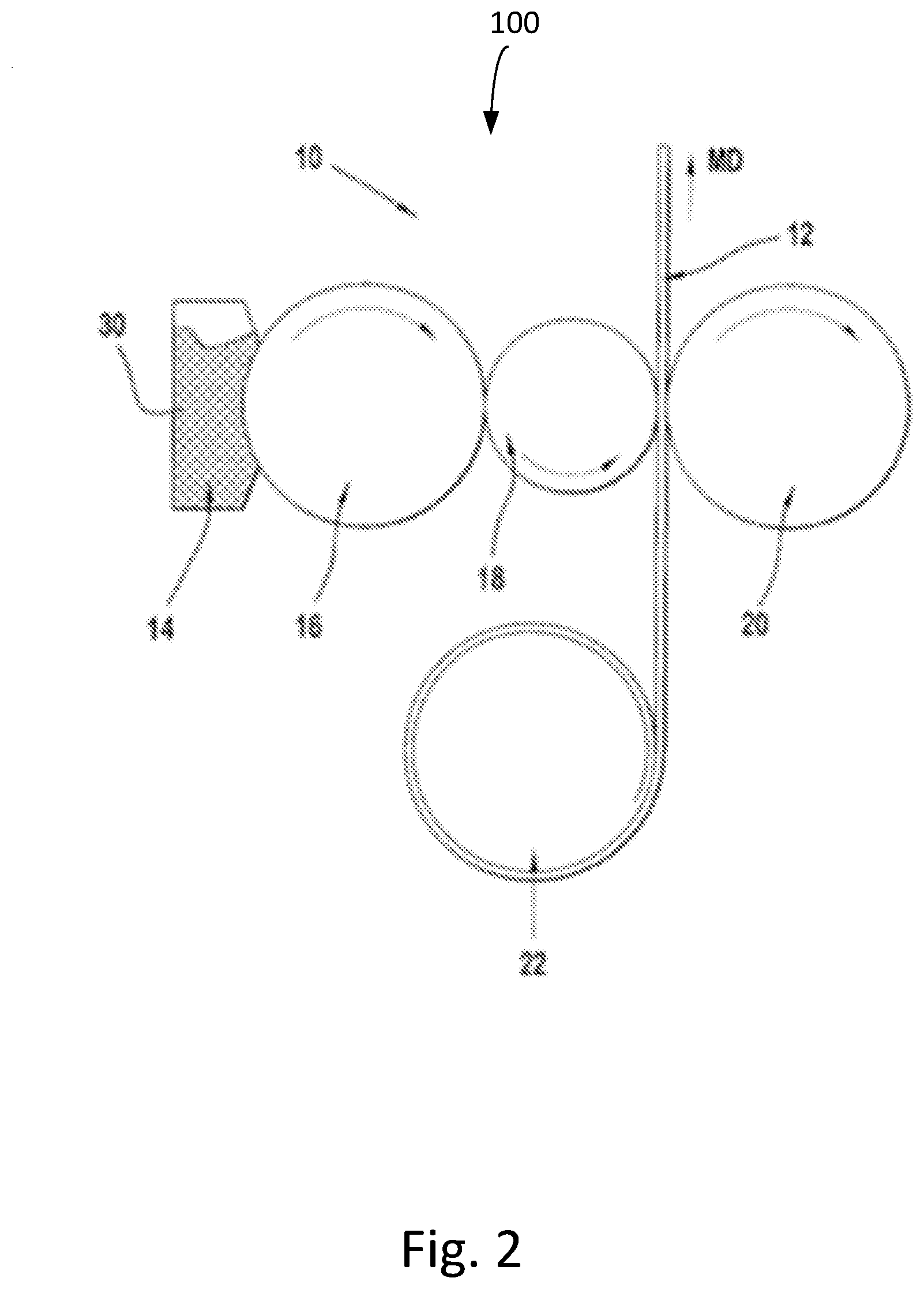
[0036] FIG. 2 is a schematic side view illustration of a flexographic printing unit;
[0037] FIG. 3 is a schematic front view illustration of a flexographic printing unit according to an embodiment of the present disclosure;
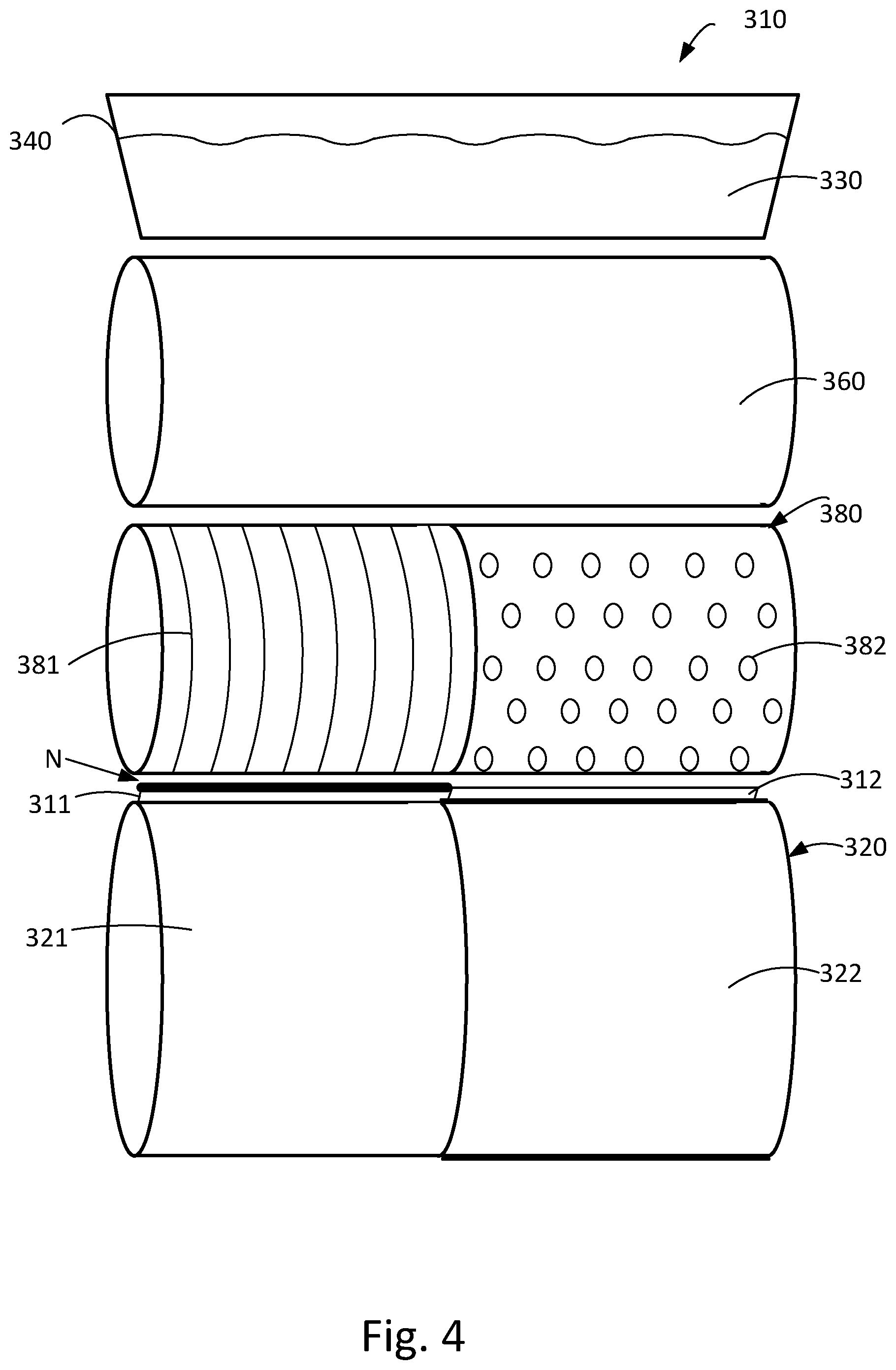
[0038] FIG. 4 is a schematic front view illustration of a flexographic printing unit according to an embodiment of the present disclosure;
[0039] FIG. 5 is a schematic front view illustration of a flexographic printing unit according to an embodiment of the present disclosure; and
[0040] FIG. 6 schematically illustrates an absorbent article with two printed nonwoven materials having different thicknesses.
DETAILED DESCRIPTION
[0041] According to the present disclosure at least two material webs having different thicknesses are simultaneously printed in a common printing unit of a printing device as described more in detail below. The material webs are usable in absorbent articles. By thickness is meant a measure of the material dimension in a plane perpendicular to the plane of the extension of the machine direction and cross direction of the material web, herein also referred to as a Z-direction. In case the material is compressible, the thickness and the average density of the material may be measured at a pressure of 0.5 kPa as defined below.
[0042] A pressure of 0.5 kPa is applied to the nonwoven material via a foot which is smaller than the area of the sample. The foot is placed inside the area to be measured. The thickness of the sample is measured while subject to this pressure. The samples for which densities are to be calculated are cut out from the sample, and the surface weight (g/cm.sup.2) of these samples is calculated from their mass/surface area. From the surface weight and the thickness, the average density of these areas is calculated. The average density (kg/m.sup.3) is calculated by dividing the surface weight by the thickness.
[0043] An absorbent article or garment as understood in the present disclosure is defined as an article or garment used for the absorption of body fluids, including but not limited to, infant diapers and training pants, adult incontinence products, feminine hygiene products such as sanitary napkins and panty liners, gender specific absorbent products, and pet training absorbent articles. The absorbent articles of the mentioned type may also be referred to as wearable absorbent articles. The absorbent articles usually comprise a liquid permeable topsheet, a liquid impermeable backsheet and an absorbent core sandwiched there between. However, an absorbent article may also include other types of products, such as household, medical products, or the like.
[0044] An example of a wearable absorbent article 1, in which the printed material webs of the present disclosure can be used, is shown in FIGS. 1a and 1n cross in FIG. 1b. The example shown is in the form of an open diaper 1. However, other types of absorbent articles could be the above-mentioned types, e.g. pant-type diapers, sanitary napkins, panty liners, and incontinence protection articles such as incontinence pads. Also, the absorbent article could be a wound care product (not shown). The absorbent article 1 typically comprises a liquid-permeable topsheet 3, a backsheet 5 and an absorbent body 7 enclosed between the liquid-permeable topsheet 3 and the backsheet 5. The liquid permeable topsheet 3 faces the wearer's body during use and is arranged to absorb body liquids such as urine and blood. The material of the topsheet 3 may e.g. comprise a nonwoven material of spunbond type, a meltblown material etc, and may be comprise several types of materials. The topsheet may comprise topsheet materials having different thicknesses. The backsheet 5 is typically liquid-impermeable, optionally breathable and may e.g. comprise a plastic (e.g. polyolefin) film, a plastic coated nonwoven or a hydrophobic nonwoven, and may also comprise a combination of different materials, which may have different thicknesses. Any one of the topsheet, backsheet and the core may comprise a printed image or pattern, and may thus be printed by the printing device or by using the printing method of the present disclosure.
[0045] The absorbent body 7 acts to receive and contain liquid and other bodily exudates. The absorbent article contains absorbent materials. Examples of commonly occurring absorbent materials are cellulosic fluff pulp, tissue layers, superabsorbent polymers, absorbent foam materials, absorbent nonwoven materials or the like. The absorbent body 7 may be constructed from several layers, such as a liquid acquisition or distribution layer or a storage layer in order to fulfil functions which are desired for an absorbent body; i.e. capacity to quickly receive liquid, distribute it within the body and store it. The layers of the absorbent body are designed to receive a large amount of liquid in a short time and distribute it evenly across the absorbent body. The size and absorbent capacity of the absorbent body may be varied to be suited for different uses such as for baby diapers, sanitary napkins and incontinence pads.
[0046] Various parts of the absorbent article may include a printed image or pattern, such as the backsheet, topsheet and the core. Wearable absorbent articles may comprise further parts to improve the fit or to assist the attachment of the article to the user, such as wings, leg cuffs, waist elastics or a waist portion, a fastening system, a landing zone, side panels, handles, fastening tabs, a pocket, spacers, or combinations thereof (not shown). Each of these parts may include a printed image or pattern.
[0047] Thus, the material webs to be printed according to the present disclosure includes various types of materials, such as nonwoven materials and plastic films, such as plastic films of PE (polyethylene) or PP (polypropylene), PET (polyethylene terephthalate), PLA (polylactic acid) and/or amyl, or, for that matter, any other thermoplastic polymer, or a mixture or copolymers of the aforementioned polymers. The material web may also be a laminate comprising at least two or more material layers of the above-mentioned type.
[0048] The term "nonwoven material" refers to a primarily fibrous assembly, which has structural integrity obtained by mechanical interlocking or by fusing fibers or by bonding by means of a cementing medium, such as starch the fibers. Thus, no weaving and/or knitting are/is involved. Also, the nonwoven is other than a traditional paper, woven, or knit. Nonwoven materials can be produced from the binding of natural and/or synthetic fibers, and are materials such as spun-bonded, SMS (spun bond, melt blown spun bond), SSMS, SMMS, carded, hydroentangled, spun laced, ultrasonically welded, as well as nonwovens made out of nanofibers, polypropylene tow, spunmelt highloft and the like. The nonwoven material may be also an airlaid material, meaning that a web of separated fibers or staple fibers is produced by laying the fibres on a wire and by forming a web in the presence of an airstream. The web may be bonded by using e.g. thermal resins. However, other types of nonwoven material may be included, particularly those that may be applied as an inner or outer layer of an absorbent article or garment. Preferably, the grammage of the nonwoven material is in the range of 1-100 gsm (grams per square meter). However, this range may be more or less, depending on application and design preference. The material web may consist or comprise of other materials present in an absorbent article.
[0049] According to a variant, the material web to be printed may be a spunlace, also referred to as spunbond, nonwoven material. A spunlace nonwoven product is derived from a process of entangling a web of loose fibres through multiple rows of jets of water at high pressure; this process entangles the fabrics and interlinks the fibres. There are several terms for spunlace nonwoven fabric or spunlaced, such as jet entangled, needled, hydroenentangled or hydraulic, but the term spunlace or spunlaced is the most popular in the nonwoven industry. The raw material for spunlace web material can be polypropylene (PP), polyethylene (PE) polyester (PET), polyamide (PA), cellulosic fibres or a combination of these and different weights and compositions are possible, such as viscose, polyester, cotton, nylon and microfibre, wherein viscose is the most commonly used raw material. Thus, if a combination of different fibres is used, this can be a mixture of fibres from different polymers, although each fibre can also include different polymers (e.g. PP/PE bi-component fibres or PP/PE copolymers). The spunlace material usually comprises polypropylene or polyethylene fibres which provide for optimal comfort for the nonwoven material. Other suitable fibres for making the nonwoven material are for example natural fibres such as bamboo, cotton and flax. The grammage of the spunlace nonwoven material can be typically from 25-120 gsm or from 40-90 gsm. The thickness of the material may vary of from 0.1 to 3 mm, such as 0.3 to 2.5 mm.
[0050] One type of the material web to be printed may be high loft nonwoven, which may be a spunmelt nonwoven. Spunmelt is a generic term describing the manufacturing of nonwoven webs directly from thermoplastic polymers. It encompasses two processes and the combination of both: spunlaid (also known as spunbond) nonwoven and meltblown nonwoven. In a spunlaid process, polymer granules are melted and molten polymer is extruded through spinnerets. The continuous filaments are cooled and deposited on to a conveyor to form a uniform web. Some remaining temperature can cause filaments to adhere to one another, but this cannot be regarded as the principal method of bonding. The spunlaid process has the advantage of giving nonwovens greater strength, but raw material flexibility is more restricted. Co-extrusion of second components is used in several spunlaid processes, usually to provide extra properties or bonding capabilities. In meltblown web formation, low viscosity polymers are extruded into a high velocity airstream on leaving the spinneret. This scatters the melt, solidifies it and breaks it up into a fibrous web. The liquid acquisition sheet material may be of a spunbonded material and may be a spunbond-meltbond-spunbond (SMS) material. The high loft nonwoven layer may in particular have a thickness ranging from 0.3 mm to 4.0 mm, for example 1.0 mm as measured at a pressure of 0.5 kPa (according to the test method described further below). The grammage, i.e. basis weight of the high loft material may for example range from 15 gsm to 500 gsm, in particular from 30 gsm to 200 gsm, such as 30-90 gsm, for example 64 gsm.
[0051] The material web to be printed may further be a carded nonwoven, which can be produced by means of airlaid process after fibers have been separated and aligned. The carded web can be bonded by means of one or more technologies used in connection with airlaid technology to provide integrity for the fabric. Further, the material web can be an airlaid nonwoven which can be produced with fluff or wood pulp. The fluff fibres are dispersed into a fast mowing air stream and condensed onto a moving screen by means of pressure and vacuum. The web can be bonded with resin and/or thermal plastic resin dispersed within the pulp. The web can be thermobonded (by heat), latex bonded (with adhesive) or multibonded (a combination of thermo and latex bonding) or mechanically bonded (high compression and temperature, bonding by hydrogen). The grammage of the airlaid nonwoven can suitably be from 30-150 gsm or from 50 to 100 gsm. The thickness of the web can vary from 0.1 to 3 mm, such as from 0.5 to 2.5 mm.
[0052] The material web to be printed may be aimed for use as a topsheet material, which normally lies in direct contact with the wearer's body. The topsheet material is preferably soft, comfortable and liquid-permeable. The topsheet can comprise any of the nonwoven materials discussed above and may be a combination of several types of material webs which are placed in different parts of the topsheet. Further examples of topsheet materials are porous foams, apertured plastic films etc. The topsheet may comprise different materials having different thicknesses. The present printing device comprising a printing unit configured for simultaneously printing at least two material webs having different thicknesses can be used for printing the topsheet material which has different thicknesses in different parts of the absorbent article.
[0053] The backsheet lies in contact with the wearer's garments, and is liquid-impermeable. The backsheet refers to the liquid impervious material forming the outer cover of the absorbent article. The backsheet can comprise a thin plastic film, e.g. a polyethylene or polypropylene film, a nonwoven material coated with a liquid impervious material, a hydrophobic nonwoven material, which resists liquid penetration, or a laminate of a plastic film and a nonwoven material. Other laminate materials which are suitable for use as the backsheet are laminates of a nonwoven material and high loft material. The backsheet material may be breathable so as to allow vapour to escape from the absorbent core, while still preventing liquids from passing there through. Examples of breathable backsheet materials are porous polymeric films, nonwoven laminates of spunbond and meltblown layers and laminates of porous polymeric films and nonwoven materials. Preferably, the backsheet comprises nonwoven material in at least the garment-facing surface thereof. The backsheet material may also comprise different materials having different thicknesses. The present printing device comprising a printing unit configured for simultaneously printing at least two material webs having different thicknesses can be used for printing the backsheet material which has different thicknesses in different parts of the absorbent article.
[0054] With reference to FIG. 2, an example of a flexographic printing device 10 for printing on a continuous web of nonwoven material 12 is schematically shown in a side view. The device includes one printing unit 100, which includes a printing ink chamber 14, an anilox roller 16, a print roller 18, and an impression roller 20. It should be noted that the printing device 10 may include several printing units, for example if multi-color printed designs are to be provided on the printing materials. In the FIG. 1 only one web of nonwoven material can be seen in the side view, but as is clear, the printing device of the present disclosure is configured to print at least two material webs having different thicknesses. The webs are fed between a print roller 18 and an impression roller 20 from a master roll 22, which is a storage roll, for a nonwoven material. The material web is fed in a machine direction (MD). The material webs are printed when the webs pass a printing nip formed between the printing roller, on which a printing cliche is mounted, and the impression roller.
[0055] By cliche, which is also referred to as cliche or flexographic (flexo) printing plate, is in this disclosure meant a substrate, a plate of polymeric rubber type or plastic material sheet, such as photopolymeric material, or an engraved metallic plate, which carriers the image to be printed. The image to be printed may also be provided an engraved printing sleeve or as an engraved printing roller. The plate used may have the image areas raised above the non-image areas. The thickness of the cliche may be for example within 0.5 to 4 mm, but is not limited thereto. The cliche is mounted on a printing roller and therefore the thicker the cliche is, the larger the radial extension of the cliche will be. The amount of cliche s mounted on the printing roller can be varied, but at least one printing cliche is used to print one or several material webs. The cliche may have substantially the same radial extension over the whole area of the cliche. Alternatively, and according to a variant of the present invention, the thickness of the cliche and thus the radial extension of the cliche when mounted on the printing cylinder, is adapted to the thickness of the material web to be printed. In case of only one printing cliche, the cliche may have areas of different thicknesses adapted to the thickness of the material web to be printed. Alternatively, there may be a dedicated cliche for each respective material web to be printed, and each of the cliche s may have a thickness adapted to the thickness of the material web to be printed.
[0056] Each of the nonwoven material webs may comprise multiple layers of material and they may be fed from a feeding device. The feeding device may comprise at least one master roll, i.e. a storage roll containing the material web or webs to be printed, for the at least two material webs. The at least two material webs having different thicknesses may be attached to each other in a parallel manner in machine direction prior to the printing process, and thus the webs may be fed from a common master roll 22. However, the feeding device may comprise a respective master roll 22 for each of the material webs to be printed.
[0057] In general, the anilox roller 16 rotates in a clockwise (CW) direction and carriers ink 30 from the printing ink chamber 14 to the print roller 18. The print roller 18 is disposed adjacent to the anilox roller 16 and rotates in an counterclockwise direction (CCW). Ink 30 from the anilox roller 16 is transferred to protruding graphic design portions on a printing cliche on the outer circumference of the print roller 18. The printing cliche mounted on the print roller 18 may include a removable sleeve, printing plate, or the like, for containing the particular design.
[0058] The impression roller 20, which rotates in a clockwise (CW) direction, is disposed adjacent to the print roller 18 and on the opposite side of the material web 12, such that the cliche on the print roller 18 is pressed against and printed on the material web 12. However, it should be understood that the rollers may rotate in the opposite direction, so long as the rollers are appropriately coordinated.
[0059] With reference to FIG. 3 an example of a flexographic printing unit 210 in a flexographic printing device according to the present disclosure is schematically shown. The printing unit 210 comprises a printing ink chamber 240 for a printing ink 230, an anilox roller 260, which transfers the printing ink to the printing roller 280 comprising two printing cliche s 281 and 282 and an impression roller 220, which presses towards the printing roller 280 during printing. The printing unit is configured for simultaneously printing at least two material webs 211, 212 having different thicknesses. The first material web 211 is thicker than the second material web 212. In the illustrated example, the radial extension of the at least one cliche 282, when mounted on the printing roller 280, is adapted in respect to the thickness of the thinner second material web 212 to be printed. More specifically, the printing roller 280 contains an equal amount of cliche s and material webs, i.e. two cliche s 281 and 282, and two material webs 211 and 212. The cliche s 281 and 282 have a radial extension adapted to the thickness of the respective material web to be printed, and thus the second cliche 282 and therefore has a larger radial extension than the first cliche 281. Suitably, the larger radial extension may be provided by means of providing cliche s having different thicknesses in a way corresponding to the different thicknesses of the material webs. The material of the thicker cliche may be more flexible than the thinner cliche, whereby it can be pressed more towards an anilox roller 260 than the thinner cliche. The anilox roller provides a printing ink 230 from a printing ink chamber 240 to the printing roller 280 and the cliche s thereof. Alternatively or additionally, to obtain larger radial extension, a further material layer can be provided between a printing roller and a cliche. In FIG. 3 this would mean that a further material layer is provided between the printing roller 280 and the second cliche 282 adapted to print on the thinner second material web 212. The thinner the material web is, the larger the radial extension of the cliche can be arranged. For example, if the first material has a thickness of 1 mm and the second material is 10% thinner, i.e. 0.9 mm, the second cliche should compensate for the thickness difference of 0.1 mm in a corresponding way. In this way, the distance between the second material web 212 and the second cliche 282 will be close to the same as the distance between the first material web 211 and the second cliche 281. Also, since the material webs are printed when they pass a printing nip (N) formed between the printing cliche mounted on the printing roller and the impression roller, the nip pressure will be more equal along the axial extension of the printing roller than in case the cliche s had a same radial extension. By axial extension is meant the extension in a direction of the center axis of a roller, which has a substantially circular cylindrical shape. In the illustrated drawings, the axial extension is in the horizontal direction. In this way, the process control and resulting printing quality may be improved.
[0060] According to another variant of the present disclosure, the radial extension of the surface of the impression roller can be additionally or alternatively to the example described above be adapted in respect to the thickness of the material webs to be printed. FIG. 4 shows schematically an arrangement of such printing unit 310 in a flexographic printing device comprising a printing unit configured for simultaneously printing at least two material webs 311, 312 having different thicknesses. The printing unit 310 comprises a printing ink chamber 340 for a printing ink 330, an anilox roller 360, which transfers the printing ink to the printing roller 380 comprising two printing cliche s 381 and 382. Alternatively only one large printing cliche with two separate printing patterns 381 and 382 could be used instead. The first material web 311 is thicker than the second material web 312. The printing unit comprises an impression roller 320 having two surface zones, a first surface zone 321 and a second surface zone 322, i.e. an equal amount of zones as there are material webs 311 and 312. The surface zones 321 and 322 have a radial extension adapted to the thickness of the respective material web 311 and 312 to be printed. In the illustrated example, the radial extension of the second surface zone 322 of the impression roller 320 is adapted in respect to the thickness of the thinner second material web 312 to be printed. More specifically, surface zones 321 and 322 have a radial extension adapted to the thickness of the respective material web to be printed, and thus the second surface zone 322 has a larger radial extension than the first surface zone 321. Suitably, the larger radial extension may be provided by means of providing a covering means 323 to the impression cylinder 320. The covering means 323 may be an elastic sheet, e.g. rubber sheet or a metallic sheet or folio. By providing such covering means, an easy and quick configuration of the printing unit to the different material thicknesses can be obtained. Alternatively or additionally a covering means in the form of a cushioning means may be provided under a surface cover material of the impression cylinder 320. In this way a simple configuration of the printing unit can be made in a more permanent way, i.e. the cushioning means needs not to be changed in between different printing runs, if material webs with the same thickness difference are to be printed also in the next run. The thinner the material web to be printed is, the larger the radial extension of the zone of the impression cylinder needs to be. The larger radial extension can be provided by means of providing a thicker covering means 323 over the zone adapted to print on the thinner material. For example, if the second material is 10% thinner than the first material web, the second surface zone should compensate for the thickness difference in a corresponding way. In this way, the distance between the second material web 312 and a cliche 382 mounted on the printing roller 380 is close to the same as the distance between the first material web 311 and the second cliche 381, when the impression cylinder 320 presses the webs 311 and 312 towards the printing roller 380 during the printing process. Thus, when the material webs are printed when they pass a printing nip (N) formed between the printing cliche mounted on the printing roller and the impression roller, the nip pressure will be more equal along the axial extension of the printing roller than in a case where the surface of the impression cylinder 320 had a same radial extension. In this way, the process control and resulting printing quality may be maintained at a same level as if the material webs had the same thickness.
[0061] With reference to FIG. 5, a further example of a flexographic printing unit 410 in a flexographic printing device is shown which printing unit 410 is configured for simultaneously printing at least two material webs 411, 412 having different thicknesses. The embodiment shown could be an alternative to the above-mentioned embodiments or it could be used in combination with any one of the above-described embodiments. As in the examples above, the first material web 411 is thicker than the second material web 412. The printing unit 410 comprises a printing ink chamber 440 for a printing ink 430, and two anilox rollers 461, 462, which transfer the printing ink to the printing roller 480 comprising two printing cliche s 481 and 482. It should be clear that only one large printing cliche with two separate printing patterns 481 and 482 could be used instead. In the illustrated example, the radial extension of the anilox roller 461 and anilox roller 462, respectively is adapted in respect to the thickness of the material web 411 and 412 to be printed. In the illustrated example, the printing unit 410 comprises an equal amount of anilox rollers and material webs, and each of the anilox rollers 461 and 462 has a radial extension adapted to the thickness of the respective material web 411, 412 to be printed. In connection with anilox rollers and as shown in FIG. 5, the anilox rollers 461, 462 may have substantially the same radius, but the radial position of each of the anilox rollers is adapted to the thickness of the respective material web to be printed. Thereby, the radial extension in respect of the material webs to be printed is adapted. The first anilox roller 461 is located at a larger distance from the first cliche 481 mounted on the printing roller 480, since it is adapted to feed ink 440 to the first cliche which prints on the first material web 411, which is thicker than the second material web 412. In an alternative variant, which is not shown, the anilox roller could be a single anilox roller as in connection with the embodiments shown in FIGS. 3 and 4. To provide different amount of ink to the respective cliche 481, 482, the anilox roller could be inclined in an axial direction, meaning that the anilox roller is tilted in respect of the center axis of the printing roller 480, which normally has its center axis parallel to the the center axis of the anilox roller 460. By inclined in axial direction is thus meant that a center axis of the anilox roller is inclined compared to a plane of the the center axis of the printing roller.
[0062] All the variants for the printing unit described above in connection with FIG. 3-5 could be combined in any manner. For example, it could be possible to use all the variants or combine a thicker cliche shown in FIG. 3 with the impression cylinder of FIG. 4 and/or the anilox roller/rollers described in connection with FIG. 5. Also, the printing device may comprise more than one printing unit as described above. For example in the printing device there may be from 1 to 8 printing units as described above. The printing units may be configured to print different colors or coat the material web with a substance. If more than 8 units were needed, several printers could be positioned after each other, and in this way it would be feasible to have even more units in the printing process.
[0063] The present disclosure also relates to a method of simultaneously printing at least two material webs having different thicknesses in a printing device comprising a printing unit as described above. In the method the printing unit is adapted to print the webs by arranging: [0064] I. the radial extension of the surface of the printing roller carrying the image to be printed such that it is adapted in respect to the thickness of the respective material web to be printed; and/or [0065] II. the surface of the impression roller such that the radial extension along the surface of the impression roller is adapted to the thickness of the material webs to be printed; and/or [0066] III. the surface of the anilox roller such that the radial extension along the surface of the anilox roller is adapted to the thickness of the material web to be printed by means of arranging a respective anilox roller to the respective material web and/or by axially inclining the anilox roller.
[0067] The steps I, II and II may be performed as described above in connection with FIG. 3-5. As mentioned above the at least one printing cliche may comprise a first printing pattern zone adapted to print on the first material web and a second printing pattern zone adapted to print on the second material web. Alternatively, a first printing cliche comprising a first printing pattern is configured to print on the first material web and a second printing cliche comprising a second printing pattern is configured to print on the second material web.
[0068] It should be noted that more than two webs could be printed. For example three material webs can be printed. The method thus comprises printing on the three material webs having at least two different thicknesses, and wherein the printing roller comprises a printing cliche for the respective material web. All three material webs may have different thicknesses or two of the material webs may have the same thickness. For example, if the material web is to be used in a diaper, incontinence article or a sanitary napkin, the two outermost material webs may be thicker than the material web located between the outermost material webs. In this way it could be possible to provide a printed web suitable for use in an absorbent article as schematically shown in FIG. 6 and provide soft side edges for the article. The absorbent article comprises a topsheet comprising thicker side edge portions 611 with a first printed image 60. The middle section 612 of the article 61 comprises a thinner nonwoven material provided with a second printed image 70. The side edge portions 611 and the middle section of the topsheet are connected to each other, e.g. by means of gluing or welding the webs together. The first printed image 60 may be used to hide a connecting seam.
[0069] In the method the first material web and the second material web may be simultaneously fed to the printing unit where a respective printing pattern on the respective first and second webs is printed. In the method, the first material web and the second material web may be separate webs, and wherein the method comprises feeding the webs from separate feeding devices or master rolls. Alternatively, the first material web and the second material web may be connected to each other in a parallel manner, such as by means of welding or gluing, and the method may thus comprise feeding the webs from a common feeding device comprising a common master roll. Also, as is clear more than two material webs can be printed simultaneously. However, the amount of material webs to be printed simultaneously is preferably up to and including six material webs. For example, in case of three material webs, the webs may be separate webs and the method may comprise feeding the webs from separate feeding devices. Alternatively, and as mentioned above, the three material webs may be connected to each other in a parallel manner, such as by means of welding or gluing, and the method comprises feeding the webs from a common feeding device.
[0070] According to a variant, and as also shown in connection with FIGS. 3 to 5 the printing patterns provided by the first and second cliche s may be different from each other.
[0071] The present disclosure also relates to the material web printed by the method as described above. Since the printing unit is adapted to the different material thicknesses, it is possible to provide a printed material web with equal printing quality in all webs. The material web may be a nonwoven, a plastic film, a woven material, a laminate or a combination thereof. Suitably, the printed material web is used in a hygiene absorbent article comprising a topsheet, backsheet, an absorbent core between the topsheet and the backsheet, and optionally side panels, leg elastics, waist elastics and/or a belt.
[0072] Although the above discussion has been exemplified through a sanitary napkin, the present invention is also applicable to other absorbent articles such as diapers, incontinence pads or panty-liners. For instance, application of the invention to diapers would provide similar benefits in terms of comfort, fit and leakage-prevention. The invention should not be considered as limited by the above description; rather the scope and limitations of the invention are defined by the enclosed claims.
* * * * *
D00000
D00001
D00002
D00003
D00004
D00005
D00006
XML
uspto.report is an independent third-party trademark research tool that is not affiliated, endorsed, or sponsored by the United States Patent and Trademark Office (USPTO) or any other governmental organization. The information provided by uspto.report is based on publicly available data at the time of writing and is intended for informational purposes only.
While we strive to provide accurate and up-to-date information, we do not guarantee the accuracy, completeness, reliability, or suitability of the information displayed on this site. The use of this site is at your own risk. Any reliance you place on such information is therefore strictly at your own risk.
All official trademark data, including owner information, should be verified by visiting the official USPTO website at www.uspto.gov. This site is not intended to replace professional legal advice and should not be used as a substitute for consulting with a legal professional who is knowledgeable about trademark law.