Apparatus And Methods For Mapping High Energy Radiation Dose During Radiation Treatment
Pogue; Brian W. ; et al.
U.S. patent application number 16/975301 was filed with the patent office on 2021-01-07 for apparatus and methods for mapping high energy radiation dose during radiation treatment. The applicant listed for this patent is THE TRUSTEES OF DARTMOUTH COLLEGE. Invention is credited to Petr Bruza, David Gladstone, Lesley A. Jarvis, Brian W. Pogue, Irwin Tendler.
| Application Number | 20210001153 16/975301 |
| Document ID | / |
| Family ID | |
| Filed Date | 2021-01-07 |
| United States Patent Application | 20210001153 |
| Kind Code | A1 |
| Pogue; Brian W. ; et al. | January 7, 2021 |
APPARATUS AND METHODS FOR MAPPING HIGH ENERGY RADIATION DOSE DURING RADIATION TREATMENT
Abstract
A system for dosimetry includes a radiation source that provides a pulsed radiation beam to a treatment zone, and a thin sheet of scintillator disposed between the radiation source and skin of a subject in the treatment zone. A gated camera images the scintillator integrating light from the scintillator during multiple pulses of the radiation beam while excluding light received between pulses of the pulsed radiation beam; and an image capture and processing machine that receives images from the gated camera and performs additional corrections to provide a map of dose received by the subject.
| Inventors: | Pogue; Brian W.; (Hanover, NH) ; Bruza; Petr; (Lebanon, NH) ; Gladstone; David; (Norwich, VT) ; Jarvis; Lesley A.; (Hanover, NH) ; Tendler; Irwin; (Hanover, NH) | ||||||||||
| Applicant: |
|
||||||||||
|---|---|---|---|---|---|---|---|---|---|---|---|
| Appl. No.: | 16/975301 | ||||||||||
| Filed: | February 22, 2019 | ||||||||||
| PCT Filed: | February 22, 2019 | ||||||||||
| PCT NO: | PCT/US19/19135 | ||||||||||
| 371 Date: | August 24, 2020 |
Related U.S. Patent Documents
| Application Number | Filing Date | Patent Number | ||
|---|---|---|---|---|
| 62634083 | Feb 22, 2018 | |||
| Current U.S. Class: | 1/1 |
| International Class: | A61N 5/10 20060101 A61N005/10; G01T 1/20 20060101 G01T001/20; G01T 1/15 20060101 G01T001/15; G01T 7/00 20060101 G01T007/00 |
Goverment Interests
GOVERNMENT INTEREST
[0002] This invention was made with government support under grants R44 CA199836 and R01 EB023909 awarded by the National Institutes of Health. This invention was made with government support using Shared Resources from the Norris Cotton Cancer Center core facilities under grant P30 CA023106 awarded by the National Institutes of Health. The Government has certain rights in the invention.
Claims
1. A system for dosimetry, comprising: a radiation source adapted to provide a pulsed radiation beam to a treatment zone; a thin sheet of scintillator disposed between the radiation source and skin of a subject, the thin sheet of scintillator being in the treatment zone; a gated camera configured to image the sheet of scintillator; and an image capture and processing machine coupled to receive images from the gated camera; wherein the gated camera is configured to capture images of light from the thin sheet of scintillator during a plurality of pulses of the pulsed radiation beam while excluding light received from the thin sheet of scintillator between pulses of the plurality of pulses of the pulsed radiation beam to form a scintillation image.
2. The system of claim 1 wherein the thin sheet of scintillator is a conformal sheet of scintillating material in contact with skin of the subject.
3. The system of claim 2 wherein the system further comprises a 3-D imaging camera, and wherein the image capture and processing machine is configured to process images from the 3-D imaging camera into a three-dimensional model of the subject and to use the three-dimensional model of the subject to correct the scintillation image while determining a corrected total dose image.
4. The system of claim 1 wherein the image capture and processing machine is configured to subtract a background image from the scintillation image, the background image being obtained by the gated camera at times excluding times of pulses of the pulsed radiation beam.
5. The system of claim 4 wherein the system further comprises a 3-D imaging camera, and wherein the image capture and processing machine is configured to process images from the 3-D imaging camera into a three dimensional model of the subject and to use the three dimensional model of the subject to correct the scintillation image while determining a corrected total dose image.
6. The system of claim 5 wherein the image capture and processing machine further comprises a database containing calibration information associated with individual thin sheets of scintillator, and the image capture and processing machine is configured to correct the scintillation image according to the calibration information.
7.-16. (canceled)
Description
CROSS-REFERENCE TO RELATED APPLICATIONS
[0001] This application claims the benefit of priority from U.S. Provisional Patent Application No. 62/634,083 filed Feb. 22, 2018, which is incorporated herein by reference in its entirety.
BACKGROUND
[0003] Several technologies exist for surface dosimetry of subjects undergoing external-beam radiotherapy; dosimetry being used to verify the amount of radiation delivered and placement of ionizing radiation doses delivered during external beam radiation therapy (EBRT). Among the dominant technologies for measurement of surface dose are film, thermo-luminescent dosimeters (TLD), optically-stimulated luminescence dosimeters, silicon diode or MOSFET dosimeters, or scintillator fibers; each of these measurement approaches has issues.
[0004] Among these issues is a large burden on staff time in reading out the measurement, especially when TLDs and film are used. Further, application of tethered detectors decreases patient comfort due to the necessity of affixing not only the detectors, but also the readout fibers or wires to the patient's body.
SUMMARY
[0005] In an embodiment, a system for dosimetry includes a radiation source that provides a pulsed radiation beam to a treatment zone, and a thin sheet of solid scintillator disposed between the radiation source and skin of a subject in the treatment zone. A gated camera images the solid scintillator integrating light from the solid scintillator during multiple pulses of the radiation beam while excluding light received between pulses of the pulsed radiation beam; and an image capture and processing machine that receives images from the gated camera and performs additional corrections to provide a map of dose received by the subject.
[0006] In another embodiment, a method for mapping skin dose of a subject during radiation treatment performed with a pulsed radiation beam in a treatment zone includes providing a thin sheet of plastic scintillator in contact with skin of a subject; positioning the subject in the treatment zone; and capturing a scintillation image of light received from the plastic scintillator during multiple time windows during pulses of the radiation beam while excluding light received from the plastic scintillator between pulses of the radiation beam. The method also includes capturing a background image of light received during a plurality of time windows, that are non-overlapping the radiation pulse and that have width corresponding to the radiation pulses; and subtracting the background image from the scintillation image.
BRIEF DESCRIPTION OF THE DRAWINGS
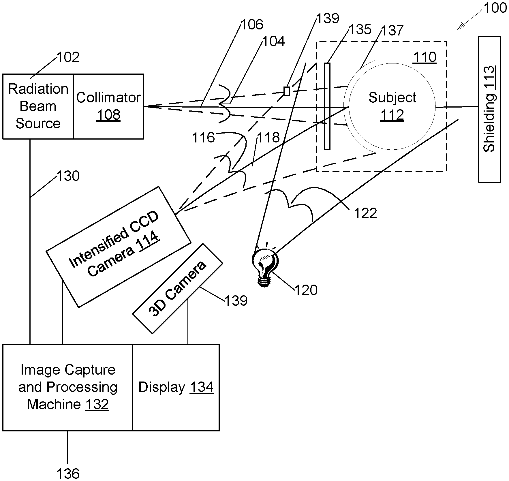
[0007] FIG. 1 is a plan view of a treatment system and facility illustrating key equipment used during radiotherapy, in an embodiment.
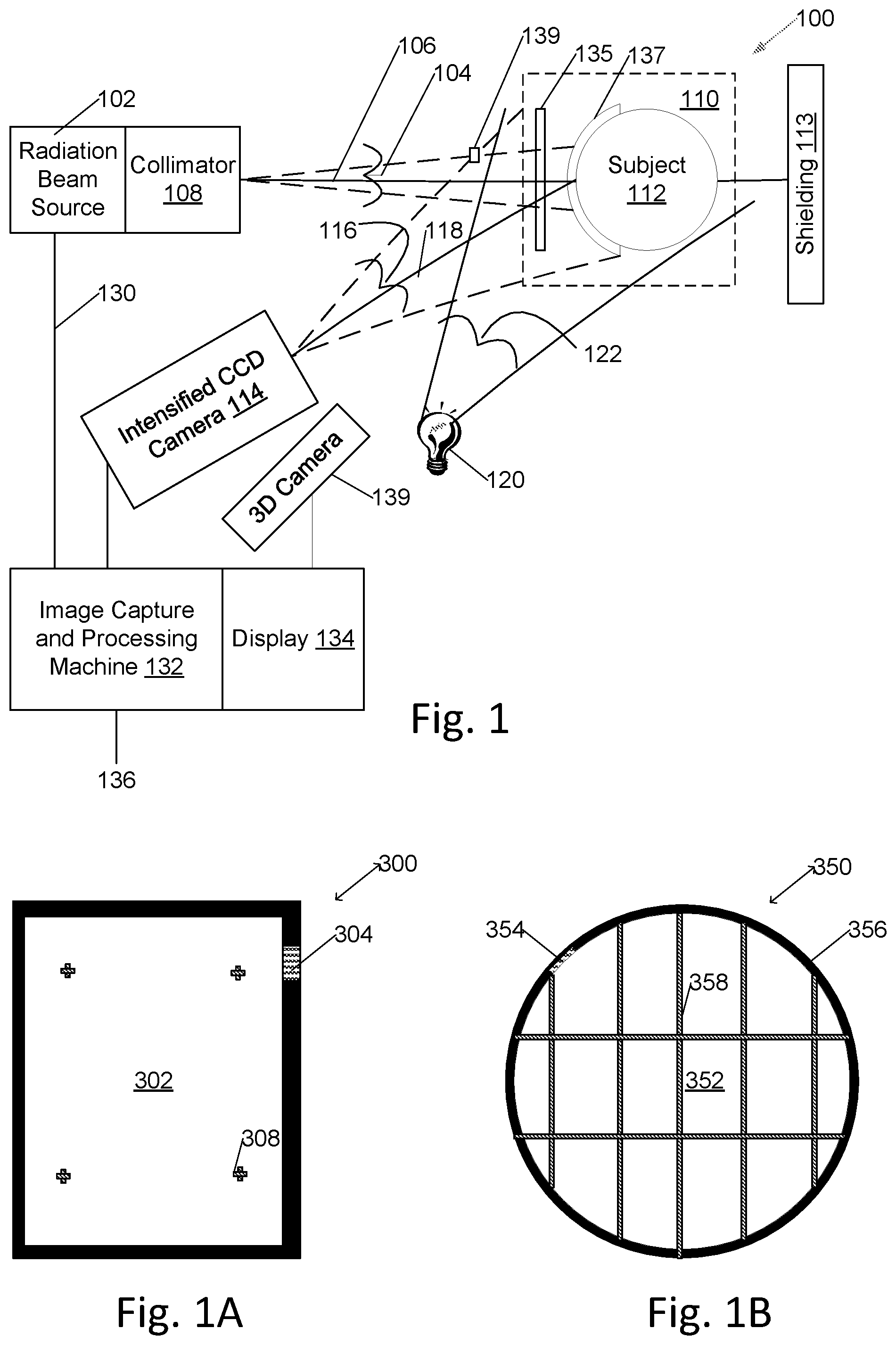
[0008] FIG. 1A depicts a thin, rectangular, conformal sheet of scintillator as used in the treatment system, with black border and identifying bar code.
[0009] FIG. 1B depicts a thin, round, conformal sheet of scintillator as used in the treatment system, with black border and identifying bar code.
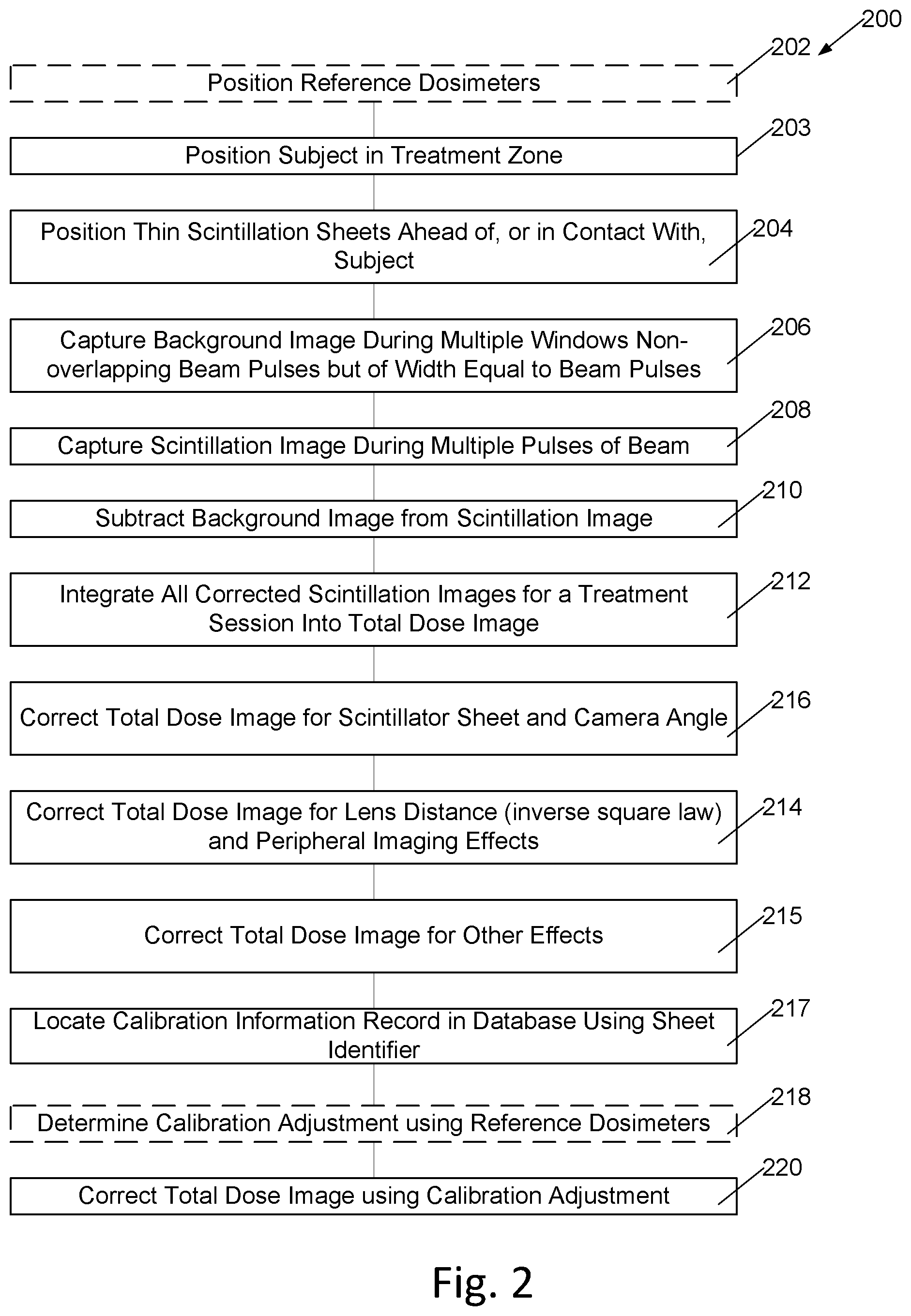
[0010] FIG. 2 is a flowchart of operation of a system for radiation dosimetry during radiation therapy.
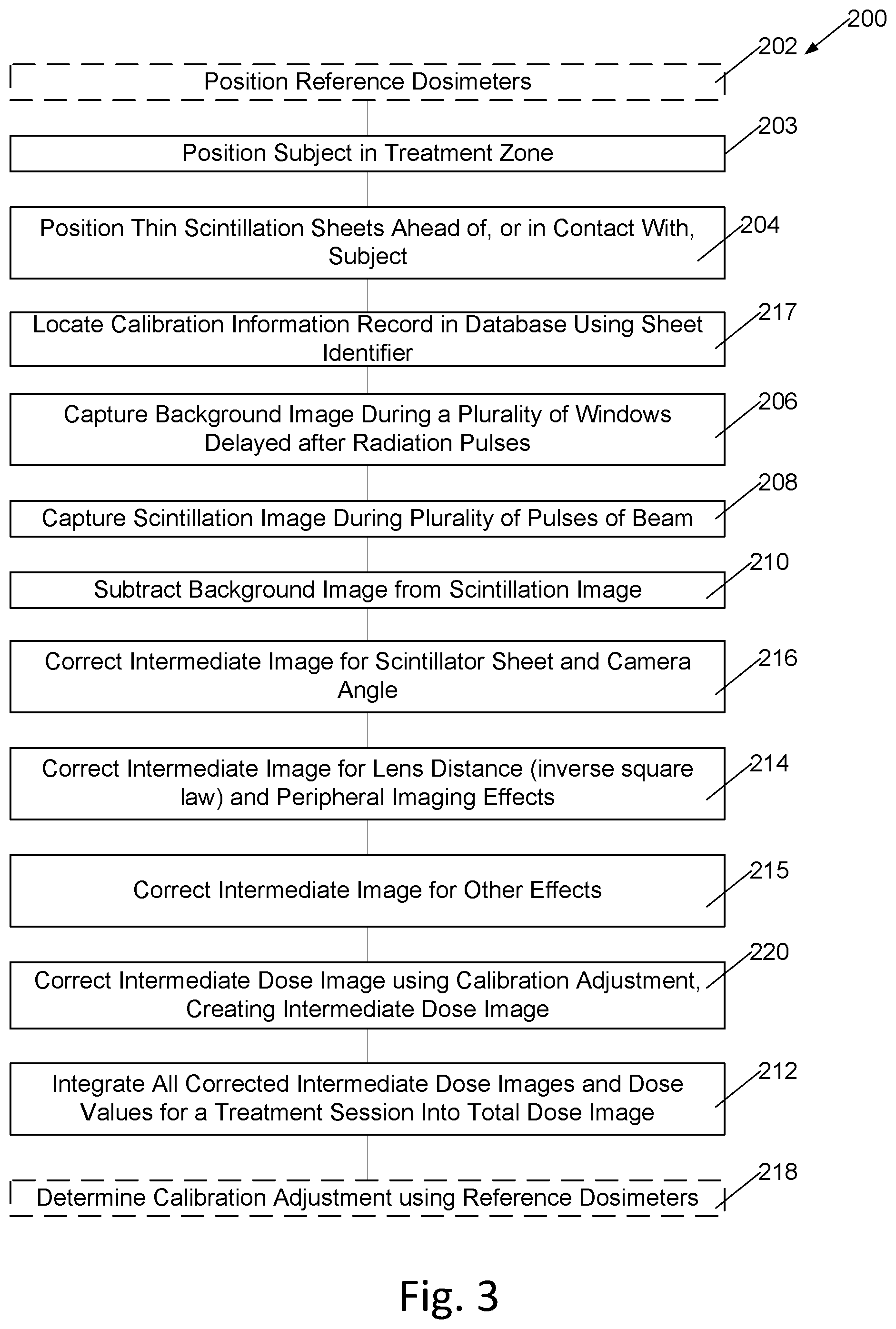
[0011] FIG. 3 is a flowchart of an alternative embodiment of operation of a system for radiation dosimetry during radiation therapy where some steps are performed in a different order than in the embodiment of FIG. 2.
DETAILED DESCRIPTION OF THE EMBODIMENTS
[0012] A radiation treatment system 100 (FIG. 1) includes a radiation source 102 of a beam 104 of pulsed, ionizing, radiation of moderate to high energy such as a linear accelerator (LINAC), cyclotron, or other particle accelerator. Beam 104 is emitted along a beam axis 106 through a collimator 108 that may include adjustable shielding shapes configured to determine a shape of beam 104. The beam axis 106 and beam 104 are aimed towards a treatment zone 110 within which a subject 112 may be positioned. Shielding 113 is positioned at least behind treatment zone 110, and in particular embodiments surrounding the entire system 100 to absorb any radiation of beam 104 not absorbed by subject 112.
[0013] A gated electronic camera, such as an intensified charge-coupled device (ICCD) camera 114, is positioned outside beam 104 with a field of view 116 aligned along a camera viewing axis 118; camera viewing axis 118 is aligned such that field of view 116 includes a view of most or all of treatment zone 110 including a view of a surface of any subject 112 that may be positioned within the treatment zone 110.
[0014] In an alternative embodiment, an image-intensified CMOS (ICMOS) camera is substituted for ICCD camera 114; with this camera image capture gating is performed in a manner like that described herein for the ICCD camera. In yet another embodiment, an electronically-gated, sensitive, CMOS (EGCMOS) camera is used in place of ICCD camera 114 with image capture timed to coincide with beam pulses as described herein.
[0015] For comfort of subject 112, one or more room lighting devices 120 are provided that provide room lighting illumination 122 to the treatment zone 110 and surrounding portions of the room in which the treatment zone 110 is located.
[0016] Pulse timing signals 130 are provided by radiation source 102 to an image capture and processing machine 132 equipped with a display 134 and network connection 136 over which images can be viewed and transmitted to external medical records storage systems (not shown).
[0017] Pulse timing signals 130 are used by image capture and processing machine 132 to synchronize time-gated imaging by ICCD camera 114 so camera 114 captures and images light received by ICCD camera 114 during each pulse of radiation source 102 while excluding from images light received by ICCD camera 114 at times between pulses of radiation source 102. In a particular embodiment, radiation source 102 is a LINAC providing a radiation beam 104 of high energy electrons in pulses of between three and four microseconds width repeated at a 360 Hertz rate, a duty cycle of approximately one in one thousand. In an alternative embodiment, radiation source 102 is a pulsed source of a radiation beam 104 of high-energy X-ray or gamma-ray photon radiation.
[0018] By imaging only during the short pulses of electron radiation emitted by the accelerator, ambient background light is suppressed by a factor of 1000, making low-intensity scintillation imaging feasible without need to blank room lighting devices 120.
[0019] It is known that some substances, such as europium-doped calcium fluoride or thallium-doped sodium iodide crystals, scintillate (or emit visible light) when they absorb high-energy charged particles or high energy photons. Some radiation detectors, including the detectors in some gamma-ray cameras, operate by localizing flashes of light produced by scintillation in such crystals when radiation is absorbed. For high-energy radiation below a saturation limit, scintillation crystals and materials emit light proportional to both the photon or particle energy and photon or particle quantity of high energy radiation absorbed by them. An issue with classical scintillation crystals is that thick crystals of high-density materials absorb most, if not all, of electron beam radiation striking them and thereby partially or fully shield part or all of any subject positioned behind them. As such, thick scintillation crystals positioned in beam 104 between collimator 108 and subject 112 would block treatment of some or all of subject 112. Such crystals would also absorb a significant percentage of photon-beam radiation such as X or gamma-ray radiation.
[0020] A plastic scintillation material, Eljen EL-240, (Eljen Technology 1300 W. Broadway, Sweetwater, Tex.) has been formed as a one-millimeter thin sheet, thin enough to pass a majority of beam 104, and having low enough density that the one-millimeter thin sheet does not significantly block or absorb radiation of beam 104.
[0021] In an embodiment, a one-millimeter thick sheet 135 of EL-240 scintillator is positioned as a screen at a radiation-source side of treatment zone 110 in a path of beam 104 from collimator 108 to subject 112, and ICCD camera 114 is positioned to image sheet 135.
[0022] In an alternative embodiment, a flexible one-millimeter thick sheet 137 of EL-240 scintillator is positioned in contact with skin of subject 112 in the treatment zone, and ICCD camera 114 is positioned to image sheet 137.
[0023] In alternative embodiments, thin sheets 137 of alternative flexible and stretchable scintillators formed of organic scintillators or powdered inorganic scintillators suspended in a polymer, the polymer may be a transparent plastic or synthetic rubber, are positioned conformal to skin of subject 112; in one alternative embodiment the scintillator is formed as a garment worn by subject 112. For purposes of this document, a thin sheet of scintillator is a transparent, or translucent material that either by itself, or through a second material incorporated within the material, emits pulses of light by any mechanism including scintillation, fluorescence, or Cherenkov, when stimulated by pulses of a charged particle, x-ray or gamma radiation beam, the pulses of light emitted having a wavelength adapted to capture by camera 114 and a decay time of less than twice a duration of pulses of the beam, the material being formed as a sheet thin enough to not absorb a significant portion of photons or charged particles of the beam so that at least 80% of energy of a typical radiation treatment beam passes through the material.
[0024] In an alternative embodiment, the conformal sheet of scintillator has a black border of width between three and five millimeters, inclusive.
[0025] Gated camera 114 in an embodiment is an intensified CCD camera, such as a PI-MAX4 1024i (Princeton Instruments, N.J., USA) camera, including an image-intensifier tube and a charge-coupled device semiconductor image sensor. The acceleration voltage of the image-intensifier tube is pulsed synchronous to pulses of the radiation source so that light received from the scintillation material sheets 135 or 137 is imaged by the gated camera during pulses of the beam 104, while light received between pulses of the beam 104 is ignored, to form scintillation images.
[0026] With reference to FIG. 1 and FIG. 2, in a method 200 of operating the system of FIG. 1, in some operations of the system reference dosimeters, which in a particular embodiment are thermos-luminescent dosimeters (TLD dosimeters) and in another particular embodiment are silicon-based diode or MOSFET dosimeters, are positioned 202 on subject 112 and the thin, approximately one millimeter thick, scintillator sheets 135 or 137 are positioned 204 between radiation source 102 with collimator 108 and subject 112. The subject is positioned 203 in the treatment zone 110.
[0027] A background image is captured 206 and integrated during the same number of time windows as the scintillation image, the windows are of duration equivalent in width and frequency to the time windows used to capture the scintillation images. The background image windows are timed to not overlap the beam pulse, and in a particular embodiment are delayed from beam pulses. These background image windows are timed late in the beam-pulse to beam-pulse gap to allow decay of any fluorescence in the scintillator sheet.
[0028] In an alternative embodiment, the background image is captured 206 and integrated during a greater number of wider background capture windows than the windows during which the scintillation images are captured. All background capture windows are non-overlapping pulses of the beam. The total of all the background capture windows provides a total background integration time that is a background multiple of the total integration of each scintillation image, in a particular embodiment being forty times the total integration time of a scintillation image. The background image is then divided by the background multiple to provide an averaged background image. Averaging the background image in this way filters the background image by signal averaging to reduce artifacts and noise in the background image. In these embodiments, the averaged background image is used instead of a raw background image when background is subtracted 210 from the scintillation image.
[0029] Radiation treatment begins and the CCD or CMOS image sensor integration time of camera 114 is configured to integrate light received during one or several time windows during pulses of the beam, and in a particular embodiment 25 time windows, each time window synchronized to occur during pulses of the beam, while excluding light received between the time windows from the integration, to capture 208 scintillation images.
[0030] Images captured by camera 114 representing integrated scintillation light from scintillation material sheets 135 or 137 are received into image capture and processing machine 132 where the background image is subtracted 210 from the scintillation images to form an intermediate image.
[0031] The scintillation images may in some embodiments be filtered by a rank-order filter.
[0032] During radiation treatment, intermediate images are integrated 212 to form a total dose image.
[0033] In one embodiment, the scintillation light output, as imaged in the scintillation images, is related to radiation dose expressed by radiant energy fluence .PHI.s (J m.sup.-2), is proportional to the received dose D=kD.PHI..sub.s, assuming ideal scintillator emission isotropy, the scintillation-dose linearity, and an electronic equilibrium established in the scintillator volume. The dose conversion factor, kD, includes the electron mass collision stopping power of the scintillator, as well as several other factors that contribute to scintillator image formation.
[0034] In embodiments, the total dose image is also corrected for scintillator-to-camera distances such as may be measured when the subject is placed in the treatment zone.
[0035] In another embodiment, the absolute dose calculation uses a total scintillation photon energy collected by the imaging system: Qs=A.OMEGA.k.sub.c.PHI..sub.s where A is the scintillator area and .OMEGA. is the solid angle projected by the imaging system subtended by the scintillator outline in the direction of the camera optical axis. The imaging system sensitivity is contained in constant k.sub.c. The scintillator image shows the intensity of scintillation radiant flux Qs, measured as a sum of all intensity values within the thresholded image, as well as the scaled radiant energy fluence, .PHI.s, measured as an average intensity value from an interior region-of-interest. This approach also requires calibration due to the projected solid angle .OMEGA., which depends on scintillator-camera distance d and angle .theta. of scintillator normal to camera optical axis.
[0036] The dose calibration factor k.sub.c is acquired at an angle .theta.=0 and at a specific scintillator camera distance d.sub.c.
[0037] An additional scintillator-camera distance calibration is carried out to mitigate a small but non-negligible effect of lens throughput at different focal distance values. The lens throughput effect may be approximated to first order by a factor k.sub.1 (d), yielding a final dose calculation formula.
[0038] The absolute dose response calibration of the scintillator imaging system si typically performed by placing the scintillator on a back-scattering water-equivalent phantom along with a group of TLDs or OSLDs. The scintillator-camera distance and angle is measured or calculated from a calibration pattern on the phantom. A scintillation intensity-dose response is then recorded for varying doses delivered to the phantom, and at two or more scintillator-camera distances. We then calculate the dose calibration factor k.sub.c at recorded scintillator distance d=d.sub.c and observation angle .theta., assuming that the angles .theta. and .rho. are small.
[0039] The image capture and processing machine 132 is configured to then compensate 214 each intermediate image and, upon completion of treatment, the total dose image, for inverse square law light loss due to differences in lens distance from scintillation sheets 135 or 137 and camera 114 to form a second intermediate image. This correction 214 is particularly useful with conformal sheets 137 applied to the subject.
[0040] In a particular embodiment, a 3-D imaging camera 139 is also positioned to image conformal scintillation material sheets 137, and image capture and processing machine 132 is configured to use images from 3-D imaging camera 139 to form a three-dimensional model of scintillation material sheets 137. In an embodiment, 3-D imaging is performed in background room lighting. The three-dimensional model is used by image capture and processing machine 132 during compensation for inverse square law light loss. In embodiments using the 3-D imaging camera and in which the image capture and processing machine 132 forms a three-dimensional model of the scintillation material sheets 137, 300 (FIG. 1A), 350 (FIG. 1B), the conformal scintillation material sheet 302, 352 may have optional markings including a black border 306, 356 of width three to five millimeters, inclusive, as well as a sheet-identifying identification bar code 304, 354; in these embodiments the markings including the black border 306, 356 aids localization of edges of the sheet in three dimensions without significantly impairing dose calculation, and the bar code 304, 354 identifies the sheet for calibration purposes. Additional, slender, markings 308, 358 may also be present on the sheet to further aid three dimensional modeling of the scintillation material sheet. In embodiments, the scintillation material sheets may be of rectangular 300 or round 350 shape.
[0041] Any other necessary corrections, such as corrections for the increased thickness of scintillator sheet penetrated by beams when sheets are oriented at angles other than perpendicular to the beam, are then made 215.
[0042] The intermediate images and total dose images are also compensated 216 for scintillator sheet angle relative to the beam axis and camera angles.
[0043] Since scintillator sheets may differ in their response to photons or charged particles of beam 104, in an embodiment each scintillator sheet is marked with an identification code, and image capture and processing machine 132 has access to a calibration database having calibration information for each sheet indexed by the identification codes of individual scintillator sheets. In a particular embodiment the identification code is a bar code printed on a visible corner of the sheet.
[0044] In embodiments using sheets with identification codes, the identification code or codes of sheets in use during a treatment session are entered into image capture and processing machine 132, or image capture and processing machine 132 reads the identification code, then accesses 217 a calibration record of the database associated with the identified sheet. If a TLD or other reference dosimeter is used during the treatment session, calibration information derived from the reference dosimeter readings are stored in the calibration record of the database associated with the identified sheet. If no reference dosimeter is used during the treatment session, averaged calibration information obtained during prior treatment sessions or during manufacturer calibration is used in calibration compensation for the treatment session.
[0045] After treatment or calibration sessions where reference dosimeters such as TLD or OSLD dosimeters are used, the TLD dosimeters are read and used to determine 218 a calibration adjustment that allows calculation of an actual dose 220 from the peak intensity or integrated intensity of each scintillator image. The calibration adjustment from prior radiation treatment sessions performed with the same scintillator sheet or sheets may in some embodiments also be used to provide real-time, estimated, cumulative dose images during treatment sessions. In treatment sessions where reference dosimeters are omitted, the total dose image is corrected using an average calibration determined from multiple prior sessions using the same or similar scintillator sheets.
[0046] In a particular embodiment, in addition to a conformal scintillator sheet 137 disposed on or worn by the subject, an additional, calibrated, reference scintillator 139 may be positioned in beam 104 and in view of camera 114. In this embodiment, light emitted during treatment by reference scintillator 139 is used to determine radiation dose available from the beam and used in place of reference dosimeter readings to calibrate individual scintillator sheets and to determine calibration adjustments for the total dose image. The corrected total dose image represents a recording of patient surface dose and is particularly applicable to total skin electron therapy patient dosimetry.
[0047] In an alternative embodiment, as illustrated in FIG. 3, an intermediate image formed by subtracting 208 the background image from the scintillation image is corrected for scintillator sheet and camera angles, lens to sheet distance, and other effects including calibration adjustments before integration 212 to form a total dose image.
Combinations of Features
[0048] The features herein disclosed may be combined in multiple ways. Among these are:
[0049] A system for dosimetry designated A, including a radiation source adapted to provide a pulsed radiation beam to a treatment zone; a thin sheet of scintillator disposed between the radiation source and skin of a subject, the thin sheet of scintillator being in the treatment zone; a gated camera configured to image the sheet of scintillator; and an image capture and processing machine coupled to receive images from the gated camera. The gated camera is configured to capture images of light from the thin sheet of scintillator during a plurality of pulses of the pulsed radiation beam while excluding light received from the thin sheet of scintillator between pulses of the plurality of pulses of the pulsed radiation beam to form a scintillation image.
[0050] A system designated AA including the system designated A wherein the thin sheet of scintillator is a conformal sheet of a plastic scintillator in contact with skin of the subject.
[0051] A system designated AB including the system designated A or AA further including a 3-D imaging camera, and wherein the image capture and processing machine is configured to process images from the 3-D imaging camera into a three-dimensional model of the subject and to use the three dimensional model of the subject to correct the scintillation image while determining a corrected total dose image.
[0052] A system designated AC including the system designated A, AA, or AB wherein the image capture and processing machine is configured to subtract a background image from the scintillation image, the background image being obtained by the gated camera at times excluding times of pulses of the pulsed radiation beam.
[0053] A system designated AD including the system designated A, AA, AB, or AC wherein the image capture and processing machine includes a database containing calibration information associated with individual thin sheets of scintillator, and the image capture and processing machine is configured to correct the scintillation image according to the calibration information.
[0054] A method designated B for mapping skin dose of a subject during radiation treatment performed with a pulsed radiation beam in a treatment zone including providing a thin sheet of scintillator in contact with skin of a subject; positioning the subject in the treatment zone; capturing a scintillation image of light received from the thin sheet of scintillator during a plurality of first time windows during pulses of the radiation beam while excluding light received from the thin sheet of scintillator between pulses of the radiation beam; capturing a background image of light received during a plurality of second time windows delayed after the first time windows and having width equal to the width of the first time windows; and subtracting the background image from the scintillation image.
[0055] A method designated BA including the method designated B or C wherein the thin sheet of scintillator is a conformal sheet in contact with skin of the subject and further including obtaining 3-D images of the thin sheet of scintillator using a 3-D imaging camera, processing images from the 3-D imaging camera into a three dimensional model of the subject, and using the three dimensional model of the subject to correct the scintillation image while determining a corrected total dose image.
[0056] A method designated BB including the method designated B, C, or BA where the thin sheet of scintillator is formed of a plastic adapted to emit light when struck by ionizing radiation.
[0057] A method designated BC including the method designated B, C, BA, or BB and further including obtaining calibration data of light emission versus applied radiation dose for the thin sheet of scintillator, and adjusting the scintillation image based on the calibration data.
[0058] A method designated BD including the method designated B, C, BA, BB, or BC wherein the radiation beam is an electron beam.
[0059] A method designated BE including the method designated B, C, BA, BB, BC, or BD where the thin sheet of scintillator is formed of a plastic adapted to emit light when struck by ionizing radiation.
[0060] A method designated BF including the method designated B, C, BA, BB, BC, BD, or BE and including obtaining calibration data of light emission versus applied radiation dose for the thin sheet of scintillator and adjusting the scintillation image based on the calibration data.
[0061] A method designated BG including the method designated B, C, BA, BB, BC, BD, BE, or BF, wherein the calibration data is stored in a database, the database indexed by identification information associated with the thin sheet of scintillator.
[0062] A method designated C for mapping skin dose of a subject during radiation treatment performed with a pulsed radiation beam in a treatment zone including providing a thin sheet of scintillator in contact with skin of a subject; positioning the subject in the treatment zone; capturing a scintillation image of light received from the thin sheet of scintillator during a plurality of first time windows during pulses of the radiation beam while excluding light received from the thin sheet of scintillator between pulses of the radiation beam; capturing a time-averaged background image of light received during a plurality of second time windows, the second time windows excluding times of pulses of the radiation beam; and subtracting the background image from the scintillation image.
[0063] Changes may be made in the above methods and systems without departing from the scope hereof. It should thus be noted that the matter contained in the above description or shown in the accompanying drawings should be interpreted as illustrative and not in a limiting sense. The following claims are intended to cover all generic and specific features described herein, as well as all statements of the scope of the present method and system, which, as a matter of language, might be said to fall therebetween.
* * * * *
D00000
D00001
D00002
D00003
XML
uspto.report is an independent third-party trademark research tool that is not affiliated, endorsed, or sponsored by the United States Patent and Trademark Office (USPTO) or any other governmental organization. The information provided by uspto.report is based on publicly available data at the time of writing and is intended for informational purposes only.
While we strive to provide accurate and up-to-date information, we do not guarantee the accuracy, completeness, reliability, or suitability of the information displayed on this site. The use of this site is at your own risk. Any reliance you place on such information is therefore strictly at your own risk.
All official trademark data, including owner information, should be verified by visiting the official USPTO website at www.uspto.gov. This site is not intended to replace professional legal advice and should not be used as a substitute for consulting with a legal professional who is knowledgeable about trademark law.