Apparatus And Methods For Securing Elastic To A Carrier Web
Hohm; Gottfried Jason ; et al.
U.S. patent application number 16/948538 was filed with the patent office on 2021-01-07 for apparatus and methods for securing elastic to a carrier web. The applicant listed for this patent is Curt G. Joa, Inc.. Invention is credited to Debra Heus Bowe, Gottfried Jason Hohm, Jeff Middlesworth, Wei Wei.
| Application Number | 20210000657 16/948538 |
| Document ID | / |
| Family ID | |
| Filed Date | 2021-01-07 |


| United States Patent Application | 20210000657 |
| Kind Code | A1 |
| Hohm; Gottfried Jason ; et al. | January 7, 2021 |
APPARATUS AND METHODS FOR SECURING ELASTIC TO A CARRIER WEB
Abstract
Apparatus and methods are provided to allow for creation of an elastic laminate. Non-stretched elastic can be laid at peaks over a nonwoven layer contained in valleys and atop peaks. Stretched elastic can be laid over tented nonwoven to create nonwoven tunnels when a second nonwoven is laid atop the first nonwoven and elastic, and the tunnels resist un-stretching of stretched elastic strands by frictional or obstruction forces. An elastic assembly or structure comprising a first and second layer of material bonded at spaced apart bond sites is disclosed, with a plurality of elastic strands disposed in a non-linear manner between said first and second layer of material, so that said strands meander in a cross-machine direction and traverse a machine direction line, restraining movement of the strands by frictional forces between the strands and the non-woven layers.
| Inventors: | Hohm; Gottfried Jason; (Oconomowoc, WI) ; Wei; Wei; (North Hollywood, CA) ; Bowe; Debra Heus; (Chilton, WI) ; Middlesworth; Jeff; (Sheboygan, WI) | ||||||||||
| Applicant: |
|
||||||||||
|---|---|---|---|---|---|---|---|---|---|---|---|
| Appl. No.: | 16/948538 | ||||||||||
| Filed: | September 23, 2020 |
Related U.S. Patent Documents
| Application Number | Filing Date | Patent Number | ||
|---|---|---|---|---|
| 14836698 | Aug 26, 2015 | 10792194 | ||
| 16948538 | ||||
| 62041876 | Aug 26, 2014 | |||
| Current U.S. Class: | 1/1 |
| International Class: | A61F 13/15 20060101 A61F013/15; A61F 13/49 20060101 A61F013/49; B29C 65/00 20060101 B29C065/00; B29C 65/08 20060101 B29C065/08 |
Claims
1. An elastic assembly comprising: a first layer of material and a second layer of material bonded together at a plurality of bond points that are spaced apart from one another, the first and second layers of material having a lengthwise direction and a crosswise direction; and a first elastic strand disposed between the first and second layers of material, the first elastic strand following a non-linear path in the lengthwise direction around respective spaced apart bond points; wherein the first elastic strand is positioned on a first crosswise side of a first bond point and is positioned on a second crosswise side opposite a first crosswise side of a second bond point that is spaced apart from the first bond point in the lengthwise direction; and wherein the plurality of bond points trap the first elastic strand between the first and second layers.
2. The elastic assembly of claim 1 comprising a plurality of tunnels defined by the first and second layers of material and by the plurality of bond points, with the first elastic strand positioned within a respective tunnel of the plurality of tunnels.
3. The elastic assembly of claim 2 wherein a frictional force between the first elastic strand and the first and second layers of material retains the first elastic strand in place.
4. The elastic assembly of claim 3 wherein the frictional force is created by positioning of the first elastic strand within a respective tunnel of the plurality of tunnels and the non-linear path of the first elastic strand in the lengthwise direction around respective spaced apart bond points creates.
5. The elastic assembly of claim 2 further comprising a second elastic strand disposed between the first and second layers of material.
6. The elastic assembly of claim 5 wherein the second elastic strand is spaced apart from the first elastic strand in the crosswise direction, with the second elastic strand positioned on a first crosswise side of a third bond point and positioned on a second crosswise side opposite the first crosswise side of a fourth bond point that is spaced apart from the third bond point in the lengthwise direction.
7. The elastic assembly of claim 5 wherein the second elastic strand is twisted together with the first elastic strand as entwined fibers positioned within a respective tunnel of the plurality of tunnels, so as to resist travel therethrough.
8. The elastic assembly of claim 1 wherein the first elastic strand is laid down on the first layer of material in a tensioned state.
9. The elastic assembly of claim 1 wherein, in following the non-linear path, the first elastic strand comprises a plurality of straight segments generally extending in the lengthwise direction and following a circuitous path in the lengthwise direction.
10. The elastic assembly of claim 1 wherein the first layer of material and the second layer of material are formed from a single web of material, with the first layer of material comprising a first portion of the single web of material and the second layer of material comprising a second portion of the single web of material that is folded over the first portion.
11. An elastic structure comprising: a first layer of material and a second layer of material bonded together at a plurality of bond points that are spaced apart from one another, the first and second layers of material having a lengthwise direction and a crosswise direction; and an elastic strand disposed between the first and second layers of material, the elastic strand positioned between a pair of upstream bond points spaced apart in the crosswise direction at a first upstream passage location and positioned between a pair of downstream bond points spaced apart in the crosswise direction at a first downstream passage location, the first upstream passage location offset from the first downstream passage location in the crosswise direction.
12. The elastic structure of claim 11 wherein the elastic strand is trapped between the pair of upstream bond points and the pair of downstream bond points, between the first and second layers of material, with friction between the elastic strand and the first and second layers of material retaining the elastic strand in place relative to the first and second layers of material.
13. The elastic structure of claim 11 wherein the elastic strand is positioned between another pair of downstream bond points spaced apart in the crosswise direction at a second downstream passage location spaced apart lengthwise from the first downstream passage location, with the elastic strand traversing a direction line extending in the lengthwise direction multiple times as it follows a non-linear path.
14. The elastic structure of claim 11 comprising a plurality of tunnels defined by the first and second layers of material and by the plurality of bond points, with the elastic strand positioned within a respective tunnel of the plurality of tunnels.
15. A method of fabricating an elastic structure comprising: providing a first layer of material having a lengthwise direction and a crosswise direction; laying down an elastic strand on the first layer of material in a non-linear manner and such that the elastic strand extends generally in the lengthwise direction; positioning a second layer of material on the first layer of material; and bonding the first and second layers of material together at a plurality of bond points; wherein the elastic strand is positioned between a pair of upstream bond points spaced apart in the crosswise direction at a first upstream passage location and positioned between a pair of downstream bond points spaced apart in the crosswise direction at a first downstream passage location, the first upstream passage location offset from the first downstream passage location in the crosswise direction.
16. The method of claim 15 comprising trapping the elastic strand between the pair of upstream bond points and the pair of downstream bond points, between the first and second layers of material.
17. The method of claim 15 comprising laying down the first elastic strand on the first layer of material in a tensioned state.
18. The method of claim 15 wherein providing the first layer of material comprises carrying the first layer of material on an anvil roll having a plurality of anvil bond points, the plurality of anvil bond points comprising protrusions on the anvil roll that raise portions of the first layer of material to provide a tenting effect at the plurality of anvil bond points to enable laying down of the elastic strand in the non-linear manner; and wherein laying down the elastic strand comprises laying the elastic strand down on the first layer of material around a portion of the protrusions in the non-linear manner.
19. The method of claim 15 comprising laying down a first portion of the elastic strand in the non-linear manner and laying down a second portion of the elastic strand in a linear manner.
20. The method of claim 15 comprising forming the first layer of material and the second layer of material from a single web of material, and wherein positioning the second layer of material on the first layer of material comprises folding the single web of material along a fold line extending in the lengthwise direction.
Description
CROSS-REFERENCE TO RELATED APPLICATIONS
[0001] The present invention is a continuation of and claims priority to U.S. patent application Ser. No. 14/836,698 filed Aug. 26, 2015, which claims priority to U.S. Provisional Patent Application Ser. No. 62/041,876, filed Aug. 26, 2014, the disclosures of which are incorporated herein by reference in their entirety.
BACKGROUND OF THE INVENTION
[0002] This invention relates to an apparatus and method for producing a laminate of elastic material by attaching a non-elongated elastic to a carrier web or webs. While the description provided relates to diaper manufacturing, the apparatus and methods are easily adaptable to other applications.
[0003] Generally, diapers comprise an absorbent insert or patch and a chassis, which, when the diaper is worn, supports the insert proximate a wearer's body. Additionally, diapers may include other various patches, such as tape tab patches, reusable fasteners and the like. The raw materials used in forming a representative insert are typically cellulose pulp, tissue paper, poly, nonwoven web, acquisition, and elastic, although application specific materials are sometimes utilized. Usually, most of the insert raw materials are provided in roll form, and unwound and applied in assembly line fashion.
[0004] In the creation of a diaper, multiple roll-fed web processes are typically utilized. To create an absorbent insert, the cellulose pulp is unwound from the provided raw material roll and pulverized by a pulp mill. Discrete pulp cores are formed by a core forming assembly and placed on a continuous tissue web. Optionally, super-absorbent powder may be added to the pulp core. The tissue web is wrapped around the pulp core. The wrapped core is debulked by proceeding through a calender unit, which at least partially compresses the core, thereby increasing its density and structural integrity. After debulking, the tissue-wrapped core is passed through a segregation or knife unit, where individual wrapped cores are cut. The cut cores are conveyed, at the proper pitch, or spacing, to a boundary compression unit.
[0005] While the insert cores are being formed, other insert components are being prepared to be presented to the boundary compression unit. For instance, the poly sheet is prepared to receive a cut core. Like the cellulose pulp, poly sheet material is usually provided in roll form. The poly sheet is fed through a splicer and accumulator, coated with an adhesive in a predetermined pattern, and then presented to the boundary compression unit. In addition to the poly sheet, which may form the bottom of the insert, a two-ply top sheet may also be formed in parallel to the core formation. Representative plies are an acquisition web material and a nonwoven web material, both of which are fed from material rolls, through a splicer and accumulator. The plies are coated with adhesive, adhered together, cut to size, and presented to the boundary compression unit. Therefore, at the boundary compression unit, three components are provided for assembly: the poly bottom sheet, the core, and the two-ply top sheet.
[0006] A representative boundary compression unit includes a die roller and a platen roller. When all three insert components are provided to the boundary compression unit, the nip of the rollers properly compresses the boundary of the insert. Thus, provided at the output of the boundary compression unit is a string of interconnected diaper inserts. The diaper inserts are then separated by an insert knife assembly and properly oriented. At this point, the completed insert is ready for placement on a diaper chassis.
[0007] A representative diaper chassis comprises nonwoven web material and support structure. The diaper support structure is generally elastic and may include leg elastic, waistband elastic and belly band elastic. The support structure is usually sandwiched between layers of the nonwoven web material, which is fed from material rolls, through splicers and accumulators. The chassis may also be provided with several patches, besides the absorbent insert. Representative patches include adhesive tape tabs and resealable closures.
[0008] The process utilizes two main carrier webs; a nonwoven web which forms an inner liner web, and an outer web that forms an outwardly facing layer in the finished diaper. In a representative chassis process, the nonwoven web is slit at a slitter station by rotary knives along three lines, thereby forming four webs. One of the lines is on approximately the centerline of the web and the other two lines are parallel to and spaced a short distance from the centerline. The effect of such slicing is twofold; first, to separate the nonwoven web into two inner diaper liners. One liner will become the inside of the front of the diaper, and the second liner will become the inside of the back of that garment. Second, two separate, relatively narrow strips are formed that may be subsequently used to cover and entrap portions of the leg-hole elastics. The strips can be separated physically by an angularly disposed spreader roll and aligned laterally with their downstream target positions on the inner edges of the formed liners.
[0009] After the nonwoven web is sliced, an adhesive is applied to the liners in a predetermined pattern in preparation to receive leg-hole elastic. The leg-hole elastic is applied to the liners and then covered with the narrow strips previously separated from the nonwoven web. Adhesive is applied to the outer web, which is then combined with the assembled inner webs having elastic thereon, thereby forming the diaper chassis. Next, after the elastic members have been sandwiched between the inner and outer webs, an adhesive is applied to the chassis. The chassis is now ready to receive an insert.
[0010] To assemble the final diaper product, the insert must be combined with the chassis. The placement of the insert onto the chassis occurs on a placement drum or at a patch applicator. The inserts are provided to the chassis on the placement drum at a desired pitch or spacing. The generally flat chassis/insert combination is then folded so that the inner webs face each other, and the combination is trimmed. A sealer bonds the webs at appropriate locations prior to individual diapers being cut from the folded and sealed webs.
[0011] The current practice in applying a stretchable web such as a poly web to a second web is involved continuously feeding the poly web into the process which results in poly running full length of product, or alternatively, full length of a constructed insert core which is then placed onto a nonwoven-type chassis. Not all machine configurations can be adapted from a full length poly chassis to a poly insert configuration due to space and/or cost restrictions. It should be understood that application of the poly web along the entire length of the product, rather than only where it is useful, increases the amount of poly material which must be utilized. This is a waste of the material resource and adds additional cost to the product. It is therefore desirable to create a lower cost product by putting poly into the product only where it is useful, instead of the complete product.
[0012] However, typical slip/cut application of poly patch to a continuous web does not work well because of the elasticity of the poly web. The slip/cut process allows the poly to slip on anvil prior to being cut causing the poly to violently snap back at the moment of cut. This can result in a short patch-long patch output from the slip/cut where one or more of the resulting poly patches are extremely distorted on the carrier web.
[0013] In certain instances, it is desirable to eliminate or minimize the use of adhesives in the manufacturing process. This results in a material savings. Also, it is desirable to reduce significant strains applied to elongated elastics that are held under significant strain of 50-400%. At this level of elongation, there is a lot of stress on the elastic and the elastic has an increased likelihood of breaking, which can lead to machine downtime.
[0014] In prior art systems, such as U.S. Pat. No. 6,291,039, it is known to capture elastics between layers of nonwoven materials. For instance, as taught therein, elastics can be placed into a hem of nonwoven material, and when the nonwoven material is bonded onto itself at the hem, the elastic can be captured within the folded over layer of material.
[0015] In U.S. Pat. No. 7,642,398 an elasticized web has a gatherable substrate and a multi-strand elastic yarn affixed to the gatherable substrate at a plurality of fixation locations. So that the yarn can be affixed to the substrate without the use of an adhesive, the yarn is subjected to forces to create partial delamination of the yarn at the fixation locations and a portion of the gatherable substrate is caused to pass between the thus delaminated strands of the multi-strand elastic yarn. A patterned surface is disclosed in which the distribution density of raised heels varies over the surface area of the patterned surface. The patterned surface comprises one or more regions along the length of the yarn in which no raised heels are present, so that the elasticized web produced using this patterned surface will have regions along the length of the elastic yarn at which no bonds are present. Accordingly, the elastic yarn will be able to move independently of the substrate or substrates in such regions.
SUMMARY OF THE INVENTION
[0016] One aspect of the invention is a method including providing a base non-woven layer, and applying thereto an elastic strand, strip or web. Throughout the specification, nonwoven webs are referred to. The references to nonwoven webs should be considered to extend to bondable webs generally, but alternative web materials are considered within the scope the invention. Examples of bondable webs which could be used in the present invention when nonwovens are referred to, are any film webs, including polypropylene or polyethylene. Commonly elastics are applied under elongation/tension to carrier webs. In the present invention, non-elongated elastics, or elastics at low tension, are provided to a carrier web. In one embodiment, the carrier web is accumulated in valleys and the elastic is bonded to the carrier web at peaks. Such bonding could be done with, but not limited to, adhesives, ultrasonics, or pressure. After bonding, the carrier web is returned to its unaccumulated state thereby elongating the elastic(s) in the process. A simple relationship between the amount of material accumulated and the distance between bond sites determines the final elongation, or strain, of the elastic(s).
[0017] In another embodiment of the present invention, elastic filaments can be separated from one another through ultrasonic force, electrostatic separation, or tension on the elastic yarn. With an electrostatic charge on the elastic filaments, the filaments separate and the filaments and nonwoven layer bond with minimal severing of the filaments.
[0018] In another aspect of the present invention, elastics are captured within layers of nonwoven materials, with the elastics laid down and captured between the nonwoven layers in a meandering pattern between bond points of nonwoven materials of the laminate. In this configuration, differently shaped and configured pins or protrusions on a roll or drum can urge the elastics to meander between bond points. In other words, the elastics can be trained to run straight, curved, meandering, or any combination of those lay down patterns, and then retained in that laydown position due to friction between the elastic material and the nonwoven material, particularly if the elastics are meandering through non-linear bond points.
[0019] Several pin and protrusion configurations (oblong, curved, rectangular, circular) can be used in different patterns on a rotating drum, such as variably spaced patterns, offset patterns, curved patterns or the like, to establish a complex pattern of elastics meandering through bond points in the nonwoven layers capturing the elastics, and the friction between the elastic and the material retains the elastic sufficiently in place to minimized adhesive bonding between the elastics and the nonwoven required to create the laminate.
BRIEF DESCRIPTION OF THE DRAWINGS
[0020] FIG. 1 is a side view of an apparatus and method of forming an elastic laminate;
[0021] FIG. 2 is a side view of an elastic laminate with an unstretched elastic and a slack base layer;
[0022] FIG. 3a is a side view of an elastic laminate with a tensioned elastic layer and a stretched or tensioned base layer;
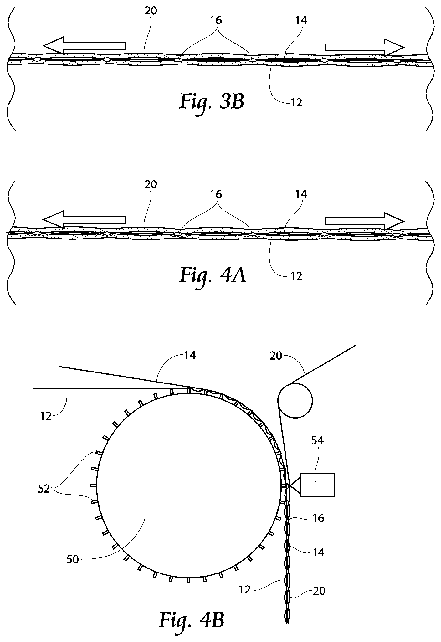
[0023] FIG. 3b is a side view of an elastic laminate with a tensioned elastic layer and a stretched or tensioned base layer, and a second material layer coupled to the elastic layer;
[0024] FIG. 4a is a side view of an elastic laminate with a tensioned elastic layer and a stretched or tensioned base layer, and a second material layer coupled to the base layer (or first material layer) at discrete bond points, with the elastic layer positioned between the first and second material layers;
[0025] FIG. 4b is a side view of an alternate embodiment of the present invention, with pins (or anvil bond points) placed about an anvil roll and carrying the first material layer, and elastic strands laid atop the first non-woven layer tented by the pins, with a second material layer laid over the elastic strands and first material layer, and the trilaminate bonded together and passed downstream for further processing;
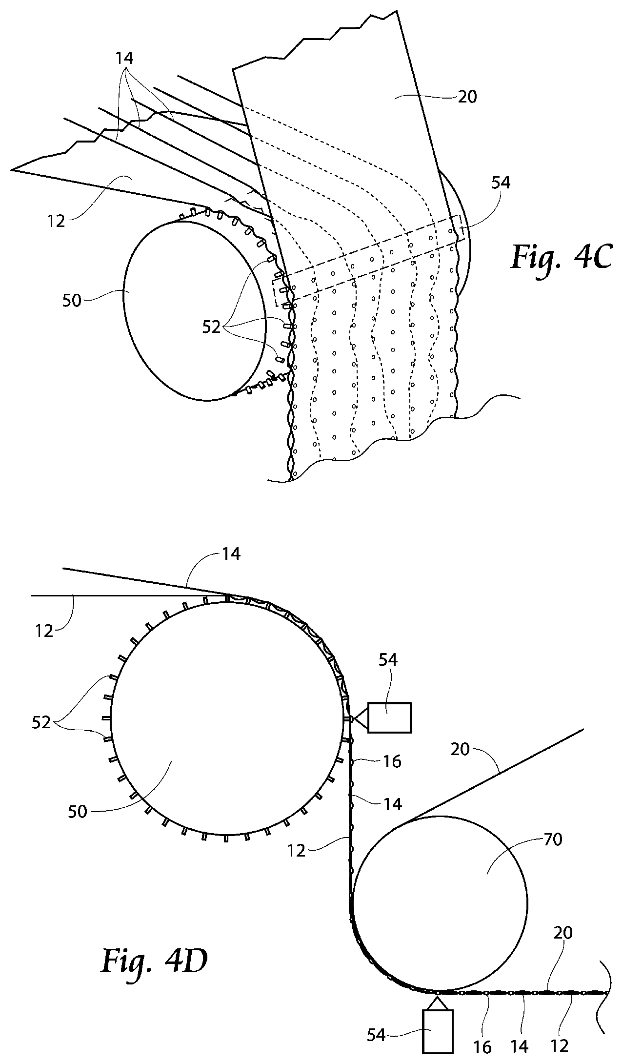
[0026] FIG. 4c is a perspective view of the machine of FIG. 4b, with elastic strands laid down atop the first material layer, and the elastic strands allowed to or encouraged to wander about the anvil bond points to be laid down and the first and second layers bonded at the bond points to secure the elastics therebetween in meandering fashion;
[0027] FIG. 4d is a side view of a machine for joining the elastic and first material layer at bond points, bringing first material layer to a taut condition, and bonding a second material layer to the laminate during a second bonding operation;
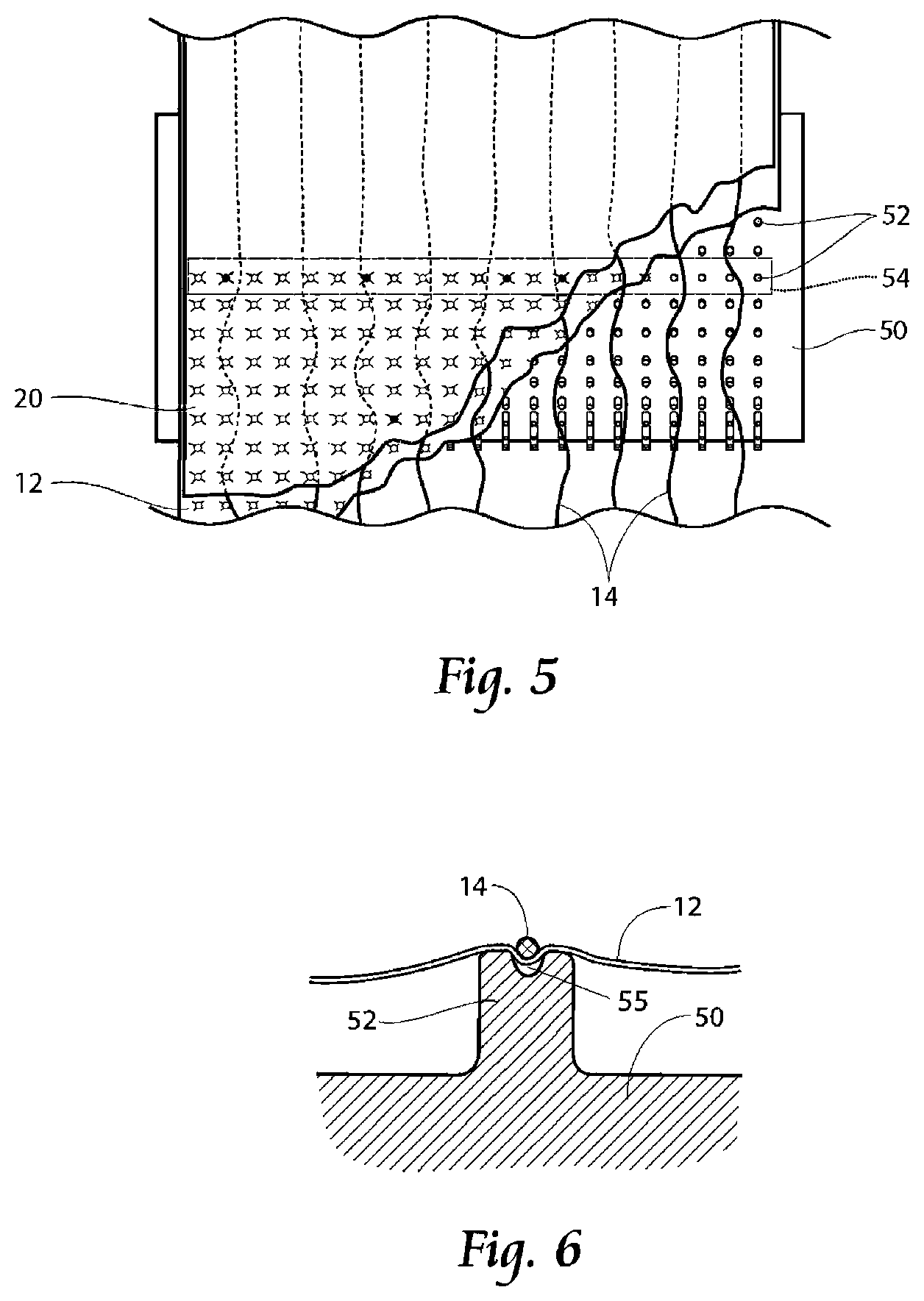
[0028] FIG. 5 is a side view of the unit of FIG. 4c, showing the trilaminate formation, with the meandering elastics trapped between the bond points of the first and second layers;
[0029] FIG. 6 is an alternate embodiment of the pinned anvil arrangement, with slots provided about the anvil.
[0030] FIG. 7 is an alternate anvil bond point configuration;
[0031] FIG. 8 is a second alternate anvil bond point configuration encouraging circuitous path of the elastic strands about the anvil bond points, the spaces between the anvil bond points (where the first and second material layers will become bonded, creating short tunnels to encourage the lacing action of the elastics between these tunnels to limit creep);
[0032] FIG. 9 is a third alternate anvil bond point configuration;
[0033] FIG. 10 is a perspective view of elastic material contained in a single material hem;
[0034] FIG. 11 is a perspective view of elastic material contained between two materials to create a trilaminate;
[0035] FIG. 12 is a fourth alternate anvil bond point configuration;
[0036] FIG. 13 is a fifth alternate anvil bond point configuration.
DESCRIPTION OF THE PREFERRED EMBODIMENT
[0037] Although the disclosure hereof is detailed and exact to enable those skilled in the art to practice the invention, the physical embodiments herein disclosed merely exemplify the invention which may be embodied in other specific structures. While the preferred embodiment has been described, the details may be changed without departing from the invention.
[0038] It is noted that the present techniques and apparatus are described herein with respect to products such as diapers, but as previously mentioned, can be applied to a wide variety of processes in which discrete components are applied sequentially.
[0039] Referring now to FIG. 1, a side view of an apparatus and method of forming an elastic laminate is shown. A base support structure 18 is provided with peaks and valleys, which can be a "V" shape. A preferably non-woven layer 12 is laid into the valleys. Atop the nonwoven 12 is laid an unstretched or relatively unstretched elastic layer 14, which can comprise strands or a web of elastic. This elastic 14 is bonded to the non-woven layer 12 at bond points 16. Such bonding could be done with, but not limited to, adhesives, ultrasonics, or pressure.
[0040] FIG. 2 is a side view of an elastic laminate with an unstretched elastic 14, and a slack base layer 12, shown just after bonding the two layers together.
[0041] After bonding, the carrier web 12 is returned to its unaccumulated state thereby elongating the elastic(s) 14 in the process, as shown in FIG. 3a. If considered mathematically, a relationship between the amount of material accumulated within the valleys, and the distance between the peaks determines the final elongation or strain (.epsilon.) of the elastics. Twice the distance from peak to valley, divided by the distance between peaks, defines (.epsilon.) of the elastics. Put another way, twice the distance from peak to valley will measure the distance between bond points of nonwoven 12 in a non-accumulated state.
[0042] If desired, as shown in FIG. 3b, a second material layer 20 (preferably nonwoven) can be coupled to the elastic 14, or in an alternate configuration, coupled to the first material layer (FIG. 4a).
[0043] In an alternative embodiment of the present invention as shown in FIG. 4b, the forming technique described with reference to FIG. 4a is shown in side view in FIG. 4b. Pins or protrusions or anvil bond points 52 are placed about an anvil roll 50, and elastic strands 14 laid atop a nonwoven layer 12 tented by the pins 52. Adjacent tented nonwoven 12 peaks create somewhat of a tunnel when coupled with top nonwoven 20, and elastic 14 is carried in the tunnel in circuitous or meandering ways as shown in FIG. 4c. The result is that the elastic 14 is restrained from lateral (or cross-machine direction) movement by encountering bond points between the first and second material layers 12 and 20 respectively, created by points 52 acting against ultrasonic horn 54. Alternatively, adhesives can be used in bonding.
[0044] Still referring to FIG. 4c, and also to FIG. 5, protrusions 52 on an anvil roll 50 carry nonwoven 12, and create a tenting effect by raising the portions of the nonwoven 12 carried by the protrusions 52. It is between and about these adjacent and downstream bond points that the elastic 14 is allowed to, or encouraged to, meander generally in the machine direction as opposed to traveling linearly in the machine direction. Elastic 14 is laid down with tension in a circuitous path over and about the protrusions 52. The elastic 14 forces the nonwoven 12 down around protrusions 52 and the protrusions 52 are used to ultrasonically bond a second, top nonwoven layer 20 to the first nonwoven 12. The elastic 14 experiences a fairly high frictional force against the bonded segments of the nonwoven layers 12 because of the serpentine (meandering) path of the elastic 14 about the bond points and against the material layers 12 and 20 themselves, keeping the elastic 14 from creeping.
[0045] Referring now to FIG. 4d, a forming technique described with reference to FIG. 3b is shown in side view in FIG. 4. In particular, after joining initially relaxed elastic 14 and initially relaxed first material layer 12 at bond points 16 by bonding unit 54, first material layer 12 and elastic layer 14 can be brought taut by elongating elastic 14. After first material layer 12 is sufficiently taut, second material layer 20 (preferably non woven) is introduced to the laminate 12/14, and a second bonding operation occurs between material layer 20 and laminate 12/14. This bonding can be performed by adhesive (not shown) or by an ultrasonic horn 54 operating against drum 70.
[0046] Referring now to FIG. 6, an alternate embodiment of the pinned anvil arrangement of FIGS. 4 and 5 is shown, with slots 55 provided about the anvil roll 50. First nonwoven layer 12, and atop that layer, the elastic 14 is laid down in slots 55, and a top nonwoven layer 20 is laid down and bonded to first nonwoven layer 12. This creates a tunnel of nonwoven, and the tight elastic 14 is resistant to creeping as described previously.
[0047] In addition to the techniques described above, modifications to the physical properties of the elastic 14 can assist providing the desired frictional resistance between the elastic 14 and nonwoven 12. For instance, ultrasonic force applied to the strands can cause the strands to unravel; those unraveled ends would choke any created tunnels in the nonwoven. Alternatively or additionally, the nonwoven layers 12 could be bonded through the unraveled strands 14, or could be unraveled without bonding.
[0048] Still alternatively or additionally, a polymer coating such as Ethylene Vinyl Acetate (EVA) could be intermittently applied on the stretched elastic strands 14, to create rings or collars of eventually solidified polymer. The eventually solidified polymer on the elastic strands 14 would provide a physical barrier on created or improvised tunnels and might even get bonded into the nonwoven bonds that form the tunnel.
[0049] Still alternatively or additionally, two or more elastic strands 14, can be twisted together, those entwined fibers 14 also physically resist travel through the created tunnels as the elastic 14 tries to relax. Additionally, a single elastic strand 14 can be rolled to make a bulky twisted structure that resists creep through the tunnel more effectively than elastic 14 that is simply stretched. Alternatively or additionally, the elastic 14 can be frayed or nicked with a rough surface such as sandpaper; it may pull the individual fibers apart or roughen the surface to fatten it up.
[0050] Referring now to FIG. 7, an alternate anvil bond point 52 configuration is shown. Bond points 52 are spaced apart in the machine direction by spacing y, and spaced apart in the cross-machine direction by spacing x. X and y can both vary and be variable between adjacent bond points 52. That is, the points can be closely spaced apart in the cross-machine or machine directions, or more distantly spaced apart, and the spacing can vary from one row to the next, and from one column to the next.
[0051] For instance, as shown in a second alternate anvil bond point configuration of FIG. 8, the bond points 52 can be spaced to encourage a circuitous path of the elastic strands 14 about the anvil bond points (noting that in a preferred embodiment that a nonwoven will be draped over the bond points 52 and the nonwoven is not shown in FIG. 8). In this configuration, a cross machine direction spacing x' offset is provided in a column of bond points 52. The spaces between the anvil bond points 52 (where the first and second material layers 12 and 20 will become bonded) creating short tunnels to encourage the lacing action of the elastics 14 between these tunnels to limit creep.
[0052] Referring to FIG. 9, third alternate anvil bond point 52 configuration varies machine direction spacing y', y'' and y'' by an offset provided between adjacent rows of bond points 52. As such, both y and x can be varied to encourage tunnel formation and encourage meandering elastics 14. Alternatively as shown in FIG. 9, the protrusions can be staggered such that protrusions of a first series of adjacent rows are not staggered in the cross machine direction. This would encourage a straight run of elastics (at the top of FIG. 9), and downstream in the machine direction, a second series of adjacent rows can be staggered or offset by a distance x' to encourage a curved run (middle portion of FIG. 9), or the staggering of x' and y' can be more random resulting in a meandering pattern of elastics 14.
[0053] Referring now to FIG. 10 elastic material 14 can be used in the present invention by single material hem of material 12. In this manner, the meandered elastic will be captured between a laminate of the first material 12 portions after folding over an outboard portion of web 12, for instance by a folding plow (not shown).
[0054] Referring now to FIG. 11, a perspective view of elastic material 14 contained between two materials 12 and 14 to create a trilaminate is shown. As can be seen, the elastic 14 meanders around bond points between material layers 12 and 14.
[0055] Referring now to FIG. 12 is a fourth alternate anvil bond point configuration is shown. A series of curved protrusions 56 can be used instead of or in addition to pins or protrusions 52 placed about an anvil roll 50 shown on FIGS. 4 and 5. In this embodiment, material layer 12 is introduced atop the roll 50, and carried in part by curved protrusions 56. Material layer 12 will somewhat drape over and about protrusions 56 to create channels encouraging elastic 14 to be laid down in a somewhat meandering pattern, such that when material layers 12 and 20 are bonded (see, e.g., FIG. 4a), the bond points between material layers 12 and 20 will result in friction between elastic 14 meandering through the bond points of material layers 12 and 20. This friction prevents elastic 14 from sliding or creeping, i.e., elastic 14 is generally retained by frictional forces in its laid down meandering pattern.
[0056] Referring now to FIG. 13, shaped protrusions 58, generally having preferably rounded corners to prevent material defects as a result of machine processing, can be used. The shape of protrusions 58 can be changed, with the spacing between shapes, and the shapes of the protrusions 58 themselves changed to accommodate the creation of frictional holding forces between elastic 14 and material layers 12 and 20, specifically between elastic 14 and bonding points between material layers 12 and 20 which elastic 14 is sandwiched between. This configuration shows a larger surface area bond point, and a patterned profile of protrusions 52 is used to provide increased frictional resistance between elastic 14, the surrounding layers 12 and 20 and their bond points. In essence, a maze is provided for the elastic 14 to go through during manufacture, and rounded corners of protrusions 52 can urge the elastic 14 to be laid down in those maze patterns during the elastic laydown and bonding processes previously described.
[0057] The foregoing is considered as illustrative only of the principles of the invention. Furthermore, since numerous modifications and changes will readily occur to those skilled in the art, it is not desired to limit the invention to the exact construction and operation shown and described. While the preferred embodiment has been described, the details may be changed without departing from the invention, which is defined by the claims.
* * * * *
D00000
D00001
D00002
D00003
D00004
D00005
D00006
XML
uspto.report is an independent third-party trademark research tool that is not affiliated, endorsed, or sponsored by the United States Patent and Trademark Office (USPTO) or any other governmental organization. The information provided by uspto.report is based on publicly available data at the time of writing and is intended for informational purposes only.
While we strive to provide accurate and up-to-date information, we do not guarantee the accuracy, completeness, reliability, or suitability of the information displayed on this site. The use of this site is at your own risk. Any reliance you place on such information is therefore strictly at your own risk.
All official trademark data, including owner information, should be verified by visiting the official USPTO website at www.uspto.gov. This site is not intended to replace professional legal advice and should not be used as a substitute for consulting with a legal professional who is knowledgeable about trademark law.