Remotely Controlling A System Using Video
Mustufa; Tabish ; et al.
U.S. patent application number 16/904482 was filed with the patent office on 2021-01-07 for remotely controlling a system using video. The applicant listed for this patent is Intuitive Surgical Operations, Inc.. Invention is credited to Brandon Itkowitz, Tabish Mustufa.
| Application Number | 20210000557 16/904482 |
| Document ID | / |
| Family ID | |
| Filed Date | 2021-01-07 |


| United States Patent Application | 20210000557 |
| Kind Code | A1 |
| Mustufa; Tabish ; et al. | January 7, 2021 |
Remotely Controlling A System Using Video
Abstract
Systems and methods for remotely controlling a system using video are provided. A method in accordance the present disclosure includes detecting a video signal of an auxiliary system at a video input, wherein the video signal including images encoded with control information. The method also includes determining that the images included in the video signal include the control information. The method further includes extracting the control information from the images. Additionally, the method includes modifying operations of the system based on the control information.
| Inventors: | Mustufa; Tabish; (Sunnyvale, CA) ; Itkowitz; Brandon; (San Jose, CA) | ||||||||||
| Applicant: |
|
||||||||||
|---|---|---|---|---|---|---|---|---|---|---|---|
| Appl. No.: | 16/904482 | ||||||||||
| Filed: | June 17, 2020 |
Related U.S. Patent Documents
| Application Number | Filing Date | Patent Number | ||
|---|---|---|---|---|
| 62869587 | Jul 2, 2019 | |||
| Current U.S. Class: | 1/1 |
| International Class: | A61B 34/35 20060101 A61B034/35; A61B 34/00 20060101 A61B034/00; A61B 34/37 20060101 A61B034/37; A61B 34/20 20060101 A61B034/20; G06T 7/20 20060101 G06T007/20; G06T 13/20 20060101 G06T013/20; B25J 9/16 20060101 B25J009/16 |
Claims
1. A system comprising: a video input; a processor; and a computer-readable data storage device storing program instructions that, when executed by the processor, control the system to: detect a video signal of an auxiliary system at the video input, the video signal including one or more images encoded with control information for the system; determine that one or more images included in the video signal include the control information; extract the control information from the one or more images; and modify one or more operations of the system based on the control information.
2. The system of claim 1, wherein the control information controls a behavior of the system.
3. The system of claim 1, wherein the control information modifies a user interface of the system.
4. The system of claim 1, wherein the video input comprises a unidirectional video input configured to solely receive video signals or audiovisual signals.
5. The system of claim 1, wherein the control information is solely transmitted within the one or more images.
6. The system of claim 1, wherein the control information is embedded in the one or more images using steganography.
7. The system of claim 1, wherein the program instructions further control the system to modify a predetermined function of the system in response to detecting the video signal.
8. The system of claim 7, wherein modifying the predetermined function comprises disabling teleoperation of the system.
9. The system of claim 1, wherein: the system comprises robotic surgical system; and one or more images comprises a video images transmitted by a mobile computing device using the video signal.
10. The system of claim 9, wherein the robotic surgical system comprises: at least one robotic arm configured to perform surgical maneuvers on a patient; a console having a three-dimensional (3D) display and one or more controls for controlling the at least one robotic arm; and modifying the one or more operations of the system based on the control information comprises selectively disabling the at least one robotic arm based on the control information.
11. A method of remotely controlling a system comprising: detecting, by a processor, a video signal of an auxiliary system at a video input, the video signal including one or more images encoded with control information; determining, by the processor, that one or more images included in the video signal include the control information; extracting, by the processor, the control information from the one or more images; and modifying, by the processor, one or more operations of the system based on the control information.
12. The method of claim 11, wherein the control information controls a behavior of the system.
13. The method of claim 11, wherein the control information modifies a user interface of the system.
14. The method of claim 11, wherein the video input comprises a unidirectional video input configured to solely receive video signals or audiovisual signals.
15. The method of claim 11, wherein the control information is solely transmitted within the one or more images.
16. The method of claim 11, wherein the control information is embedded in the one or more images using steganography.
17. The method of claim 11, further comprising modifying a predetermined function of the system in response to detecting the video signal.
18. The method of claim 17, wherein modifying the predetermined function comprises disabling teleoperation of the system.
19. The method of claim 11, wherein: the system comprises robotic surgical system; and the one or more image comprises video images transmitted by a mobile computing device via the video signal.
20. A non-transitory computer-readable storage device having program instructions stored therein, the program instructions being executable by a processor to cause a system to: detect a video signal of an auxiliary system at a video input, the video signal including one or more images encoded with control information; determine that one or more images included in the video signal include the control information; extract the control information from the one or more images; and modify one or more operations of the system based on the control information.
Description
CROSS-REFERENCES TO RELATED APPLICATIONS
[0001] This application claims priority to U.S. Provisional Patent Application No. 62/869,587, filed Jul. 2, 2019, the content of which is incorporated herein in its entirety.
FIELD
[0002] The present disclosure generally relates to remote control systems and, more particularly, relates to the remote control of a system using teleoperation.
BACKGROUND
[0003] One of the more significant medical advancements in recent decades has been in the field of surgical robotics technologies. For example, robotic surgical systems now allow surgeons teleoperative abilities to control surgical instruments with improved precision and range of motion, while also providing enhanced visualization and access to hard-to-reach areas. These systems have been able to provide patients with a minimally invasive alternative to open and laparoscopic surgeries. One such system is the da Vinci.TM. Surgical System, by Intuitive Surgical, Inc. of Sunnyvale, Calif. The da Vinci.TM. Surgical System is a robotically controlled surgical system that provides a surgeon console or control center and a patient-side cart. The patient-side cart has multiple movable arms for mechanically controlling attached surgical instruments. A drive system with a mechanical interface enables the surgeon to remotely move and position respective instruments with precision during medical procedures, while seated in the ergonomically designed console. A high-definition camera allows the surgeon a highly magnified, high-resolution 3D image of the surgical site once the camera is placed inside the patient. Coupled with the use of controllers on the surgeon console, the surgeon can translate his own hand movements into smaller, precise movements of tiny surgical instruments in the patient.
[0004] Current robotic surgical systems typically lack the functionality to interoperate with recently developed portable systems, such as mobile phones, tablet computers, and the like. The availability, power, and flexibility of such systems offer surgeons the opportunity to access information that can improve their ability to assess a patient's condition during the surgery and, thereby, provide improved results. However, modifying an existing system to accommodate these new devices typically involves significant modification the existing system's hardware, firmware, and software. It would therefore be desirable to enable recently developed systems to interoperate with existing systems, without making significant modifications to the existing systems.
BRIEF SUMMARY
[0005] The present disclosure is generally directed to performing remote control of a system using another system. A system in accordance with the present disclosure performs operations including detecting a video signal of an auxiliary system at a video input, wherein the video signal including images encoded with control information. The operations also include determining that the images included in the video signal include the control information. The operations further include extracting the control information from the images. Additionally, the operations include modifying operations of the system based on the control information.
[0006] In some implementations, an auxiliary system generates a video signal displayed by a primary system. The auxiliary system can embed control information within image data transmitted in the video signal to control modes of operation of the primary system. The control information may be embedded via steganography techniques from the mobile device. In some implementations, when the auxiliary system is communicating with the primary system, the primary system may adjust its display and user interface. In some implementations, the primary system may disable predetermined functions (e.g., teleoperations) when a user is using the auxiliary system to control the primary system. Some implementations may implement certain data security and integrity features, such as checksums or error-correcting codes. Some implementations may also employ cryptographic features for authentication and authorization.
[0007] In one exemplary implementation, the primary system can be a robotic surgical system and the auxiliary system can be a mobile device. A user of the mobile device may interact with the robotic surgical system and control information to indicate a desired state of operation for the robotic surgical system via a video signal, wherein the video signal comprises first data representing an image or video captured by the mobile device and second data representing the control information. The mobile device may selectively change the first data based on the control information and transmit the video signal to the robotic surgical system. The robot surgical system may decode the control information from the video signal and modify a mode of operation of the console based on the control information. For example, based on the control information, the surgical system performs operations such as, changing a location of a display, present a user interface, and selectively enable and disable the at least one robotic arm.
[0008] It is to be understood that both the foregoing general description and the following detailed description are exemplary and explanatory only and are not restrictive of the disclosure. Additional features of the disclosure will be set forth in part in the description which follows or may be learned by practice of the disclosure.
BRIEF DESCRIPTION OF THE DRAWINGS
[0009] The accompanying drawings, which are incorporated in and constitute a part of this specification, illustrate several implementations of the disclosure and together with the description, explain the principles of the disclosure.
[0010] FIG. 1 shows a block diagram illustrating an example of an environment for implementing systems and processes in accordance with aspects of the present disclosure.
[0011] FIG. 2 shows a block diagram illustrating an auxiliary system in accordance with an implementation of the disclosure.
[0012] FIG. 3 shows a block diagram illustrating a primary system in accordance with an implementation of the disclosure.
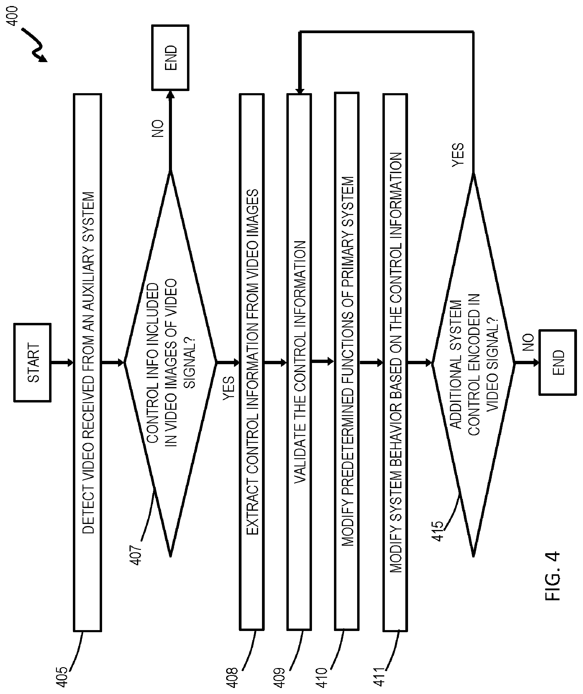
[0013] FIG. 4 shows a process flow diagram illustrating an example method of operating the gaming system in accordance with aspects of the present disclosure.
DETAILED DESCRIPTION
[0014] The present disclosure provides systems and methods for an auxiliary system to remotely control behaviors of a primary system. In some implementations, the auxiliary system can be a mobile device, the primary system can be a robotic surgical system, and the video signal can include images transmitted from a video source of the mobile device for display by the robotic surgical system. In accordance with aspects of the present disclosure, the auxiliary system may incorporate the control information into data comprising the images transmitted to the primary system. For example, the auxiliary system can embed the control information in the image data using steganography techniques. In some implementations, the control information provided by the auxiliary system controls the primary system to modify a behavior, an operation, or an output of a user interface of the primary system. For example, the surgical system may change display modes and suspend teleoperation of surgical instruments in response to receiving the control information included in video images from the mobile device. Further, some implementations may authenticate the identity and the integrity of the auxiliary system, the video connection, and the video signal. For example, the primary system and the auxiliary system may use cryptographic techniques, such as digital signatures or one-time passwords.
[0015] As disclosed herein, implementations disclosed herein enable auxiliary systems to interoperate and control an existing primary system without significant modification of the primary system. For example, the existing surgical system may have hardware, firmware, and/or software that are incompatible with a newly or recently developed mobile device. Consequently, the surgical system may be unable to interoperate with the mobile device. However, in accordance with aspects of the present disclosure, the auxiliary system can transparently embed control information (e.g., application data) in image data using steganography techniques and transmit them to an existing video input (e.g., Digital Video Interface ("DVI"), high-definition serial digital interface ("HD-SDI"), and high-definition multimedia interface ("HDMI")) of the primary system in a video signal. The primary system can detect the video signal, extract the control information from the image data contained therein, and modify its operation based on extracted control information.
[0016] FIG. 1 shows a functional block diagram illustrating an example of an environment 100 for implementing systems and processes in accordance with aspects of the present disclosure. The environment can include a primary system 105, a user interface system 107, and an auxiliary system 110. In some implementations, the environment 100 can be a surgical system, wherein the primary system 105 and the user interface system 107 are a patient-side cart and a surgeon console, respectively. For example, the patient-side cart, the surgeon console, and the electronics/control can be the same or similar to those provided in the da Vinci.RTM. Xi (model no. IS4000) commercialized by Intuitive Surgical, Inc. of Sunnyvale, Calif., as previously described herein. In some such implementations, the primary system 105 can include tools to perform minimally invasive robotic surgery by interfacing with and controlling a variety of surgical instruments. For example, the primary system 105 can include one or more user-controllable arms configured to hold, position, and manipulate various surgical instruments and other tools.
[0017] The user interface system 107 can receive (directly or indirectly) video signals 140 and user interface signals 145 from the primary system 105 and the auxiliary system 110. While FIG. 1 illustrates the user interface system 107 being directly connected to the primary system 105 and indirectly connected to the auxiliary system 110, it is understood that other implementations of the environment 100 can rearrange the primary system 105, the user interface system 107, the auxiliary system 110, and the connections therebetween. For example, as indicated by the dashed lines in FIG. 1, some implementations of the environment 100 can connect auxiliary system 110 directly to the user interface system 107. Also, some implementations can combine some or all of the hardware and functionality of the user interface system 107 with the primary system 105.
[0018] In some implementations, the user interface system 107 can include one or more user-input devices 108 for operating the primary system 105. The input device 108 can include, for example, joysticks, computer mice, computer trackballs, foot pedals, touchscreen displays, or other suitable input devices. Additionally, the user interface system 107 can include one or more display devices 109 for displaying still images and video. The display device 109 can be, for example, a cathode ray tube (CRT) display, a liquid crystal display (LCD), a light-emitting diode (LED) display, a stereoscopic display, or other suitable display technology.
[0019] In some implementations, the user interface system 107 can be a surgeon console for operating the robotic surgical system. Through the input devices, the user interface system 107 serves as a controller by which the instruments mounted at the robotic surgical system act as an implement to achieve desired motions of the surgical instrument(s), and accordingly perform a desired surgical procedure. It is understood, however, that the environment 100 is not limited to receiving inputs at the user interface system, and inputs may be received at any device which can be configured to realize a manipulation of the surgical instrument(s) at the primary system 105. For example, a surgical instrument at the primary system 105 may be manipulated at the primary system 105 through user interface system 107 in combination with another surgical instrument support device, or entirely through the other surgical support device.
[0020] Additionally, the user interface system 107 can receive image data from the primary system 105 and the auxiliary system 110, and can present such images using the display device 109. For example, the user interface system 107 can receive video signals 140 including image data from a primary video source 113 of the primary system and image data from an auxiliary video source 115 of the auxiliary system 110. The user interface system 107 can display the received images together on the display device 109. For example, the primary video source 113 can be an endoscopic camera that outputs primary video 151 that can be displayed to a surgeon using the display device 109 of the user interface system 107. Further, the auxiliary video source 115 can output auxiliary video 155 that can be displayed together with the primary video 151 on the display device 109. In some implementations, the user interface system 107 can present the primary video 151 and the auxiliary 155 as separate tiles in non-overlapping areas of the display device 109. It is understood that, in some implementations, the primary system 105 or the user interface system 107 can combine the primary video 151 and the auxiliary video 155. For example, the primary video 151 and the auxiliary video 155 can be indexed and/or overlaid to provide a single mixed image on the display device 109.
[0021] The auxiliary system 110 can be a computing system including a graphic user interface that displays images from an auxiliary video source 115. In some implementations, the auxiliary system 110 is a mobile personal computing device. For example, the auxiliary system 110 can be a laptop computer, a tablet computer, a smart phone, a video camera, or other such device. The auxiliary system 110 can be connected to the primary system 105 and the user interface system 107 by a video channel 120 and a data channel 125. In some implementations, the auxiliary video source 115 can be an image sensor of the auxiliary system 110. For example, the auxiliary video source 115 can be video captured by a camera of the auxiliary system 110 and presented on a display 117 of the auxiliary system 110. Additionally, in some implementations, the auxiliary video source 115 can be image data stored locally by the axillary system 110, or image data accessed by the auxiliary system 110 at a remote repository. Additionally, the auxiliary video source 115 can be images stored locally by the auxiliary system 110, or retrieved (e.g., accessed or streamed) from a remote system over a communication link or network (e.g., the Internet).
[0022] The video channel 120 can include one or more communication links, which can be any combination of wired and/or wireless links using any combination of video transmission techniques and video protocols. In some implementations, the video channel 120 may be a wired video link (e.g., S-video, HDMI, DVI, DisplayPort, or other suitable video connection). In other implementations, the video channel 120 can be a wireless video link (e.g., wireless home digital interface ("WHDI"), WirelessHD.TM., WiGig.TM., AirPlay.TM., Miracast.TM., WiDi.TM., or another suitable wireless video connection). Further, in some implementations, the video channel 120 can be a unidirectional video connection configured solely to transmit video signals or audiovisual signals. For example, the unidirectional video connection can be configured to solely function at particular video transmission frequencies and solely using video transmission protocols.
[0023] The information channel 125 can include one or more communication links or data links. The information channel 125 can comprise any combination of wired and/or wireless links; any combination of one or more types of networks (e.g., the Internet, a wide area network, a local area network, a virtual private network, etc.); and/or utilize any combination of transmission techniques and protocols and/or a communication networks, such as a local area network, a wide area network, or the Internet. In some implementations, the information channel can include, for example, a universal serial bus ("USB"), FireWire, Wi-Fi, Bluetooth, Ethernet, or other suitable data communication links. In some implementations, the auxiliary system 110 solely uses the information channel 125 to transmit non-video data signals 135, while solely using the video channel 120 for transmitting video or audiovisual signals 130. Some implementations lack information channels 125 and 125A, and the auxiliary system 110 solely uses the video channel 120 to communicate with the primary system 105 using the auxiliary video signal 130.
[0024] In a non-limiting example of an implementation consistent with the present disclosure, the primary system 105 can be a surgical system, and the auxiliary system 110 can be a mobile device connected to the surgical system solely by the video channel 120. For example, a user can connect the mobile device to the surgical system 100 by connecting a video transmission cable (e.g., HDMI) as the video channel 120 to a video input connector of the primary system 105 or the user interface 107. In accordance with aspects of the present disclosure, the user of the auxiliary system 110 can provide control inputs that change the behavior or state of the primary system 105 using the auxiliary system 110. The control inputs can modify behaviors, operations, and outputs of the primary system 105. For example, where the primary system is a robotic surgical system, the control information from the mobile device may cause the surgical system to change display modes. The display modes may include an interface for controlling system modes, such as: following mode (follower surgical instruments follow movements of the primary tool grips), clutch mode (disengaging follower actuation from primary movement), camera control mode (enabling endoscope movement), energy tools mode (enabling surgical energy tool control (e.g., electrocautery tools), camera focus mode (enabling camera focus control), arm swapping (allowing various primary and follower arm control combinations), and tiled auxiliary image swapping mode (also referred to as "tilepro") for enabling control of various picture displays in the surgeon's display, e.g., swapping between a full screen display and a display in which the surgeon views two or more separate images or data screens.
[0025] The auxiliary system 110 can convert the user's control inputs to control information, incorporate the control information into video images, and transmit the video images to the primary system 105 in the video signal 130 via the video channel 120. In the implementations, the auxiliary system 110 uses steganographic techniques to incorporate the control information within the video images. For example, in one implementation, the auxiliary device 110 may vary pixels at the edge of the image, or make subtle adjustments to color values of the image data (e.g., by modifying the least significant bits). By doing so, the auxiliary system 110 can minimize alterations to the video images to render image data incorporating control inputs of a user.
[0026] Further, the primary system 105 can receive the transmission of the auxiliary video signal 130 including the control information, interpret the video images to extract the control information, and modify its behavior, operation, or output of the surgical system based on the control information.
[0027] FIG. 2 shows a block diagram illustrating an auxiliary system 110 in accordance with an implementation of the disclosure. The auxiliary system 110 can include a controller 205, a video processor 215, input/output (I/O) processor 220, a display 117, and a storage system 235. In some implementations, the controller 205 can include a processor 239, memory devices 241, an I/O controller 243, a network interface 245, and a bus 247. The memory devices 241 can include a read-only memory (ROM), a random-access memory (RAM)(e.g., static RAM), and an operating system (O/S). The controller 205 can be in communication with the video processor 215, the I/O processor 220 and the storage system 235. The bus 116 can provide a communication link between the components in the controller 205.
[0028] In general, processor 239 executes computer program instructions, which can be stored in the memory devices 241 and/or the storage system 235. In accordance with aspects of the present disclosure, the program instructions can include a control translation module 255 that, when executed by the processor 220, perform one or more of the functions described herein. It is understood that the control translation module 255 can be implemented as one or more sets of program code stored in memory 241 as separate or combined modules.
[0029] While executing the computer program instructions, the processor 239 can read and/or write data to/from memory 241, storage system 235, and the control translation module 255. The program code executes the processes of the present disclosure, for example, by modifying video image data to incorporate control information. In some implementations of the present disclosure, control translation module 255 is computer program code stored in, for example, the memory device 241 or the storage system 235 that, when executed by the processor 239, causes controller 205 to performs steganographic encoding of video images. For example, the control information can be application data embedded in a video image based on ancillary data, metadata substitution, least significant bit substitution or adaptive substitution, or frequency space manipulation of data in a carrier, i.e., the original image or video signal generated by an auxiliary device. The control translation module 255 can use existing steganographic tools, such as Xiao Steganography, Image Steganography, Steghide, Crypture, Rsteg, Ssuite Piscel, OpenStego, and SteganPeg, that encode and decode information into and from images. In some implementations, control translation module 255 employs steganographic techniques to adjust pixel values (color, brightness, etc.), such as the least significant bits or metadata within a portion or across all of its display to encode application data 225, such as control information messages, user interface inputs, etc. within the image or video signal.
[0030] The video processor 215 can include an input connection 259 and output connection 261. In some implementations, the input connection 259 is solely a video input solely configured to receive video signals or audiovisual signals. Likewise, in some implementations, the output connection 261 is solely a video output solely configured to transmit video signals or audiovisual signals. The video processor 215 can process image data received from the controller 205 to drive the display 117 and to generate the auxiliary video signal 130. In accordance with aspects of the present disclosure, the image data from the controller can include control information incorporated the control translation module 255.
[0031] The I/O processor can include an input/output connection 263. In some implementations, the input connection 259 is solely a data input solely configured to receive data signals. The I/O processor 220 can process data received from the controller 205 and convert it to a data signal for transmission via the I/O connector 263. The I/O processor 220 can also process data signals received from the I/O connection 263, convert it to a data, and provide the data to the controller 205. Further, the I/O processor can exchange information with the display 117. For example, the I/O can process user inputs generated by a touch screen display.
[0032] FIG. 3 shows a block diagram illustrating a primary system 105 in accordance with some implementations of the disclosure. The primary system 105 can include a controller 305, a video processor 315, an input/output (I/O) processor 325, a storage system 335, a processor 339, memory devices 341, an I/O controller 343, a network interface 345, and a bus 247, all of which can be the same or similar to that previously described herein.
[0033] In accordance with aspects of the present disclosure, the program instructions can include a video translation module 355 and a data integrity module 357 that, when executed by the processor 339, perform one or more of the functions described herein. In some implementations, the video translation module 355 can be the same or similar to the control translation module 255 described above regarding FIG. 2. It is understood that video translation module 355 and the data integrity module 357 can be implemented as one or more sets of program code stored in memory 341 as separate or combined modules.
[0034] As will be described further below, in some implementations, the video translation module 355 detects a video signal, such as the auxiliary video signal 130 received by the primary system 105, and determine whether it contains video data including control information. If so, the video translation module 355 can modify the operation of the primary system 105 (including the user interface system 107). The primary system 105 may react to control information by, for example, adjusting its own behavior, mode, or outputs. In some implementations, the control information changes modes of the primary system to enable/disable teleoperation of the primary system 105.
[0035] The data integrity module 357 can ensure integrity of information received in the auxiliary video signal 130 to prevent unexpected system behavior of the primary system 105. In some implementations, the data integrity module 357 performs various data integrity checks, such as checksums, error-correcting code, or other suitable verification techniques, for example, based on data embedded in the control information of the auxiliary video signal 130. In one implementation, data integrity module 357 may perform cryptographic functions to verify the identity, authenticity, and authority the source of the auxiliary video signal (e.g., auxiliary system 110) before the control information is permitted to trigger behavior changes by primary system 105. For example, in one implementation, the primary system 105 may employ a varying access code such as those used in two-factor authentication (e.g., a hash function that generates a constantly-varying one-time-password from a shared secret).
[0036] The flow block diagram in FIG. 4 illustrates an example of the functionality and operation of possible implementations of systems, methods, and computer program products according to various implementations consistent with the present disclosure. Each block in the flow diagram of FIG. 4 can represent a module, segment, or portion of program instructions, which includes one or more computer executable instructions for implementing the illustrated functions and operations. In some alternative implementations, the functions and/or operations illustrated in a particular block of the flow diagram can occur out of the order shown in FIG. 4. For example, two blocks shown in succession can be executed substantially concurrently, or the blocks can sometimes be executed in the reverse order, depending upon the functionality involved. Further, in some implementations, the flow diagram can include fewer blocks or additional blocks. It will also be noted that each block of the flow diagram and combinations of blocks in the diagram can be implemented by special purpose hardware-based systems that perform the specified functions or acts, or combinations of special purpose hardware and computer instructions.
[0037] FIG. 4 shows a flow block diagram illustrating an example of a process 400 for controlling modes, behaviors, and states of a system (e.g., primary system 105) using control information incorporated into images transmitted in a video signal from an auxiliary system (e.g., auxiliary system 110). Turning to block 405 in FIG. 4, the system detects video (e.g., auxiliary video signal 130 or 130A) received from the auxiliary system. In some implementations, the system may detect a physical connection of a cable to a video connection (e.g. video input 359). In other implementations, the system can detect a wireless signal received by the video connection. Additionally, in some implementations, the system may respond to detection of the video at block 405 by providing an indication at the primary system or at a user interface (e.g., user interface system 107). For example, the system may display the received video (e.g., auxiliary video 155) on a display device (e.g., display device 109). The system may also provide an alert of the received video using, for example, an audiovisual indication or a pop-up message on the display.
[0038] At block 407, the system (e.g., executing video translation module 355) determines whether the video signal received at block 405 includes images including control information. If the video images do not include image data having control information (e.g., block 407 is "No,") the method 400 ends. On the other hand, if the system determines that the video signal includes image data having control information (e.g., block 407 is "Yes,") then at block 408 the system extracts the control information from the video images received in the video signal. For example, as described above, the system can use steganographic tools to detect and extract control information from the video signal received at block 405. At block 409, the system can validate the information received from the auxiliary system at block 405. In some implementations, the system validates the control information extracted at block 408. In some implementations, the system can validate information provided in the video signal received at block 405 prior to the extraction at block 408. The validation at block 409 can verify that the information received from the auxiliary system is authentic and that it represents actual control information. As previously described herein, validation of the information may utilize cryptographic techniques, such as digital signatures or one-time passwords. Additionally, the validation can use techniques such as cyclic redundancy check ("CRC") or checksums.
[0039] At block 410, the system can modify one or more predetermined functions based on the control information extracted at block 408. In some implementations, after validating the control information at block 409, the system can limit the functionality of the primary system or the user interface system to prevent erroneous or malicious control information from causing the primary system to perform undesirable operations. For example, modifying the predetermined functions can include suspending teleoperation of the primary system by the user interface system while receiving valid control information from the auxiliary system. Additionally, in some implementations, modifying the predetermined functions can include disabling a data input/output interface (e.g., I/O 263 and I/O processor 220) while receiving valid control information from the auxiliary system.
[0040] At block 411, the system can modify its behaviors, operations, and outputs based on the control information extracted at block 409. For example, the system may combine video generated at the system (e.g., primary video 151 from primary video source 113) with video received from the auxiliary system (e.g., auxiliary video 155 of auxiliary video source 115) to display a tiled image on a user interface (e.g., display device 109 of user interface system 107). In a particular example, the system may generate a tiled display mode (e.g., a "TilePro Mode" of the da Vinci.TM. Surgical System) including an arrangement of two auxiliary video inputs (picture archiving and communication system ("PACS"), ultrasound, room camera, etc.) along with the operative image in main display portion. Additionally, in some implementations, the control information received in the auxiliary video signal may control a size and scaling of the display. For example, when two auxiliary inputs are present, the 3D image provided by the stereoscopic display on auxiliary system 110 may be scaled on the screen.
[0041] At block 415, the system determines whether the video signal received at block 405 includes additional control information. If the video images do not include additional control information (e.g., block 415 is "No,") the method 400 ends. On the other hand, if the system determines that the video signal includes image data having additional control information (e.g., block 415 is "Yes,") then the process 400 iteratively returns to block 409 and continues as described above.
[0042] The present disclosure is not to be limited in terms of the particular embodiments described in this application, which are intended as illustrations of various aspects. Many modifications and variations can be made without departing from its spirit and scope, as will be apparent to those skilled in the art. Functionally equivalent methods and apparatuses within the scope of the disclosure, in addition to those enumerated herein, will be apparent to those skilled in the art from the foregoing descriptions. Such modifications and variations are intended to fall within the scope of the appended claims. The present disclosure is to be limited only by the terms of the appended claims, along with the full scope of equivalents to which such claims are entitled. It is also to be understood that the terminology used herein is for the purpose of describing examples of implementations and is not intended to be limiting.
[0043] With respect to the use of substantially any plural and/or singular terms herein, those having skill in the art can translate from the plural to the singular and/or from the singular to the plural as is appropriate to the context and/or application. The various singular/plural permutations may be expressly set forth herein for sake of clarity.
[0044] It will be understood by those within the art that, in general, terms used herein, and especially in the appended claims (e.g., bodies of the appended claims) are generally intended as "open" terms (e.g., the term "including" should be interpreted as "including but not limited to," the term "having" should be interpreted as "having at least," the term "includes" should be interpreted as "includes but is not limited to," etc.). It will be further understood by those within the art that if a specific number of an introduced claim recitation is intended, such an intent will be explicitly recited in the claim, and in the absence of such recitation no such intent is present. For example, as an aid to understanding, the following appended claims may contain usage of the introductory phrases "at least one" and "one or more" to introduce claim recitations. However, the use of such phrases should not be construed to imply that the introduction of a claim recitation by the indefinite articles "a" or "an" limits any particular claim containing such introduced claim recitation to embodiments containing only one such recitation, even when the same claim includes the introductory phrases "one or more" or "at least one" and indefinite articles such as "a" or "an" (e.g., "a" and/or "an" should be interpreted to mean "at least one" or "one or more"); the same holds true for the use of definite articles used to introduce claim recitations. In addition, even if a specific number of an introduced claim recitation is explicitly recited, those skilled in the art will recognize that such recitation should be interpreted to mean at least the recited number (e.g., the bare recitation of "two recitations," without other modifiers, means at least two recitations, or two or more recitations).
[0045] Furthermore, in those instances where a convention analogous to "at least one of A, B, and C, etc." is used, in general such a construction is intended in the sense one having skill in the art would understand the convention (e.g., "a system having at least one of A, B, and C" would include but not be limited to systems that have A alone, B alone, C alone, A and B together, A and C together, B and C together, and/or A, B, and C together, etc.). In those instances where a convention analogous to "at least one of A, B, or C, etc." is used, in general such a construction is intended in the sense one having skill in the art would understand the convention (e.g., "a system having at least one of A, B, or C" would include but not be limited to systems that have A alone, B alone, C alone, A and B together, A and C together, B and C together, and/or A, B, and C together, etc.).
[0046] It will be further understood by those within the art that virtually any disjunctive word and/or phrase presenting two or more alternative terms, whether in the description, claims, or drawings, should be understood to contemplate the possibilities of including one of the terms, either of the terms, or both terms. For example, the phrase "A or B" will be understood to include the possibilities of "A" or "B" or "A and B." In addition, where features or aspects of the disclosure are described in terms of Markush groups, those skilled in the art will recognize that the disclosure is also thereby described in terms of any individual member or subgroup of members of the Markush group.
* * * * *
D00000
D00001
D00002
D00003
D00004
XML
uspto.report is an independent third-party trademark research tool that is not affiliated, endorsed, or sponsored by the United States Patent and Trademark Office (USPTO) or any other governmental organization. The information provided by uspto.report is based on publicly available data at the time of writing and is intended for informational purposes only.
While we strive to provide accurate and up-to-date information, we do not guarantee the accuracy, completeness, reliability, or suitability of the information displayed on this site. The use of this site is at your own risk. Any reliance you place on such information is therefore strictly at your own risk.
All official trademark data, including owner information, should be verified by visiting the official USPTO website at www.uspto.gov. This site is not intended to replace professional legal advice and should not be used as a substitute for consulting with a legal professional who is knowledgeable about trademark law.