Cigarette And Aerosol Generation Device For Cigarette
HWANG; Jung Seop ; et al.
U.S. patent application number 16/976973 was filed with the patent office on 2021-01-07 for cigarette and aerosol generation device for cigarette. This patent application is currently assigned to KT&G CORPORATION. The applicant listed for this patent is KT&G CORPORATION. Invention is credited to Bong Su CHEONG, Sang Won CHOI, Jung Seop HWANG, Dong Kyun KO, Jae Sung NOH.
| Application Number | 20210000175 16/976973 |
| Document ID | / |
| Family ID | |
| Filed Date | 2021-01-07 |


| United States Patent Application | 20210000175 |
| Kind Code | A1 |
| HWANG; Jung Seop ; et al. | January 7, 2021 |
CIGARETTE AND AEROSOL GENERATION DEVICE FOR CIGARETTE
Abstract
Provided is a cigarette including: a tobacco rod; a first air flow delivery element adjacent to a first end of the tobacco rod and having a first porosity; and a second air flow delivery element adjacent to a second end of the tobacco rod and having a second porosity greater than or equal to the first porosity, wherein the second porosity is greater than or equal to 30%.
| Inventors: | HWANG; Jung Seop; (Daejeon, KR) ; KO; Dong Kyun; (Sejong, KR) ; NOH; Jae Sung; (Chungcheongnam-do, KR) ; CHEONG; Bong Su; (Daejeon, KR) ; CHOI; Sang Won; (Daejeon, KR) | ||||||||||
| Applicant: |
|
||||||||||
|---|---|---|---|---|---|---|---|---|---|---|---|
| Assignee: | KT&G CORPORATION Daejeon KR |
||||||||||
| Appl. No.: | 16/976973 | ||||||||||
| Filed: | November 13, 2019 | ||||||||||
| PCT Filed: | November 13, 2019 | ||||||||||
| PCT NO: | PCT/KR2019/015419 | ||||||||||
| 371 Date: | August 31, 2020 |
| Current U.S. Class: | 1/1 |
| International Class: | A24F 40/20 20060101 A24F040/20; A24D 1/20 20060101 A24D001/20; A24D 3/17 20060101 A24D003/17; A24F 40/57 20060101 A24F040/57; A24D 3/10 20060101 A24D003/10 |
Foreign Application Data
| Date | Code | Application Number |
|---|---|---|
| Nov 23, 2018 | KR | 10-2018-0146424 |
Claims
1. A cigarette comprising: a tobacco rod; a first air flow delivery element adjacent to a first end of the tobacco rod and having a first porosity; and a second air flow delivery element adjacent to a second end of the tobacco rod and having a second porosity greater than or equal to the first porosity, wherein the second porosity is greater than or equal to 30%.
2. The cigarette of claim 1, wherein the first porosity is in a range of 10% to 30%.
3. The cigarette of claim 1, wherein a ratio of the second porosity to the first porosity is greater than or equal to 1 and less than 3.
4. The cigarette of claim 1, wherein the second air flow delivery element has a tube shape having an inner diameter formed by a hollow.
5. The cigarette of claim 4, wherein a ratio of the inner diameter of the second air flow delivery element to an outer diameter of the second air flow delivery element is greater than or equal to 55%.
6. The cigarette of claim 4, wherein the inner diameter is in a range of 3.0 mm to 4.5 mm.
7. The cigarette of claim 1, wherein the first air flow delivery element and the second air flow delivery element include cellulose acetate.
8. An aerosol generating apparatus comprising: a case; a heater configured to heat a cigarette comprising: a tobacco rod; a front-end plug adjacent to a front end of the tobacco rod and having a first porosity; and a filter rod adjacent to a rear end of the tobacco rod and having a second porosity greater than or equal to the first porosity, wherein the second porosity is greater than or equal to 30%; a vaporizer configured to generate an aerosol by vaporizing a liquid composition and delivering the aerosol into the cigarette through the front-end plug; and a controller configured to control operations of the heater and the vaporizer.
Description
TECHNICAL FIELD
[0001] The present disclosure relates to a cigarette and an aerosol generating apparatus therefor.
BACKGROUND ART
[0002] Recently, the demand for alternative methods to overcome the shortcomings of traditional cigarettes has increased. For example, there is growing demand for a method of generating aerosol by heating an aerosol generating material in cigarettes, rather than by combusting cigarettes. Accordingly, studies on a heating-type cigarette and a heating-type aerosol generating device have been actively conducted.
DESCRIPTION OF EMBODIMENTS
Technical Problem
[0003] According to an embodiment, a cigarette may include a filter located at a rear end and having a greater porosity than a filter located at a front end.
Solution to Problem
[0004] According to an aspect of the present disclosure, a cigarette may include: a tobacco rod; a first air flow delivery element adjacent to a first end of the tobacco rod and having a first porosity; and a second air flow delivery element adjacent to a second end of the tobacco rod and having a second porosity greater than or equal to the first porosity, wherein the second porosity is greater than or equal to 30%.
[0005] The first porosity may be greater than or equal to 10% and less than or equal to 30%.
[0006] A ratio of the second porosity to the first porosity may be greater than or equal to 1 and less than 3.
[0007] The second air flow delivery element may have a tube shape having an inner diameter formed by a hollow.
[0008] A ratio of the inner diameter of the second air flow delivery element to an outer diameter of the second air flow delivery element may be greater than or equal to 55%.
[0009] The inner diameter may be greater than or equal to 3.0 mm and less than or equal to 4.5 mm.
[0010] The first air flow delivery element and the second air flow delivery element may include cellulose acetate.
[0011] According to another aspect of the present disclosure, an aerosol generating apparatus may include: a case; a heater heating a cigarette including a tobacco rod, a front-end plug adjacent to a front end of the tobacco rod and having a first porosity, and a filter rod adjacent to a rear end of the tobacco rod and having a second porosity greater than or equal to the first porosity, wherein the second porosity is greater than or equal to 30%; a vaporizer generating an aerosol by vaporizing a liquid composition and delivering the aerosol into the cigarette through the front-end plug; and a controller controlling operations of the heater and the vaporizer.
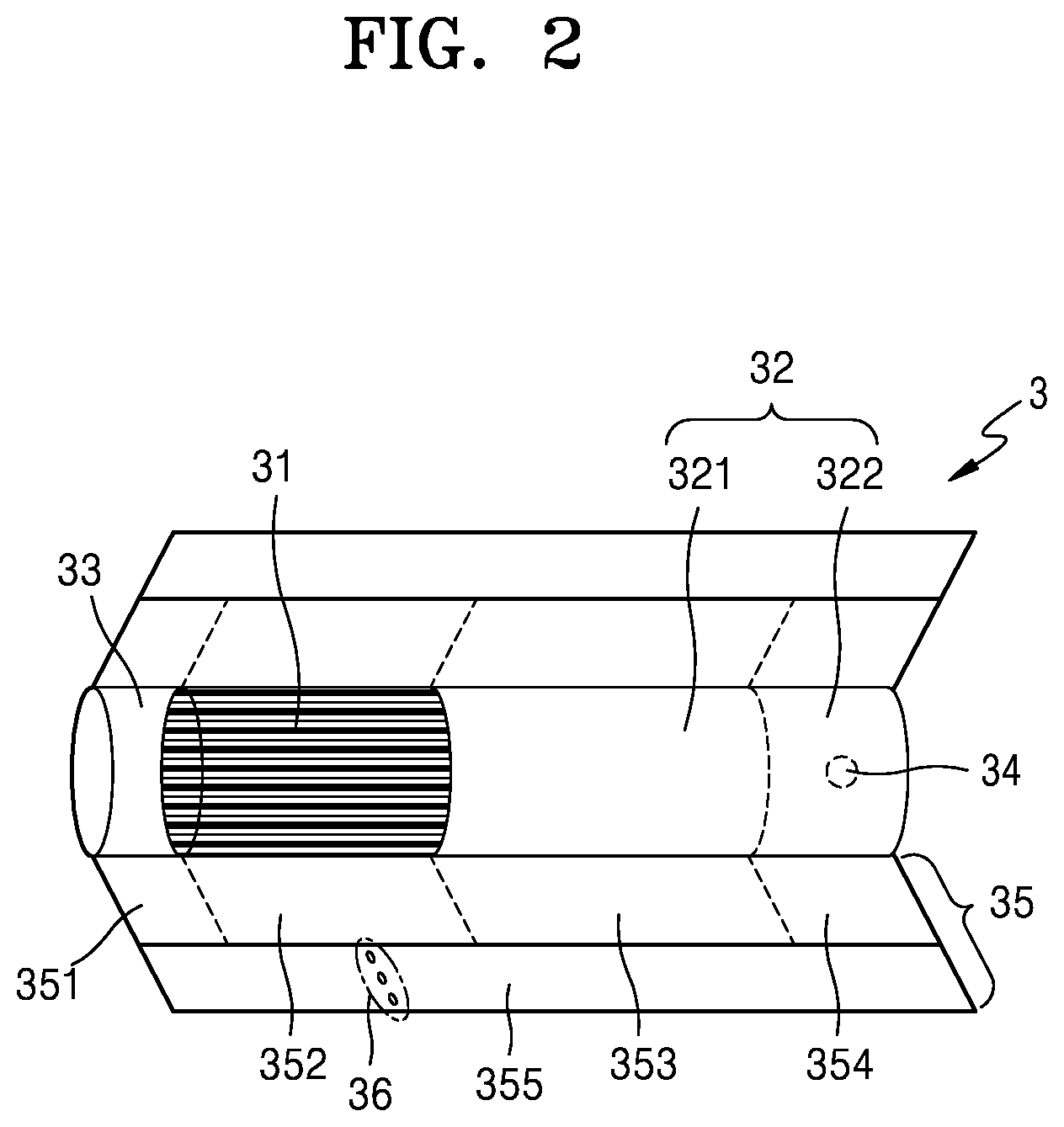
Advantageous Effects of Disclosure
[0012] According to an embodiment, a cigarette may include a filter located at a rear end and having a porosity greater than a porosity of a filter located at a front end to thereby cool mainstream smoke and a surface temperature of the cigarette at a safe temperature.
BRIEF DESCRIPTION OF DRAWINGS
[0013] FIG. 1 is a perspective view of a cigarette according to an embodiment.
[0014] FIG. 2 is a perspective view of a cigarette according to another embodiment.
[0015] FIGS. 3 and 4 are diagrams illustrating examples in which a cigarette is inserted into an aerosol generating apparatus.
[0016] FIG. 5 is a cross-sectional view taken along line A-A' of FIG. 1 and illustrating a flow of air passing through the cigarette of FIG. 1.
[0017] FIG. 6 is a cross-sectional view of the cigarette of FIG. 1 respectively taken along lines B-B' and C-C' of FIG. 1.
[0018] FIG. 7 is a view illustrating examples of a point where a temperature of mainstream smoke and a surface temperature of a cigarette are measured in the cigarette, according to an embodiment.
BEST MODE
[0019] According to an aspect of the present disclosure, a cigarette may include: a tobacco rod; a first air flow delivery element adjacent to a first end of the tobacco rod and having a first porosity; and a second air flow delivery element adjacent to a second end of the tobacco rod and having a second porosity greater than or equal to the first porosity, wherein the second porosity is greater than or equal to 30%.
[0020] According to another aspect of the present disclosure, an aerosol generating apparatus may include: a case; a heater heating a cigarette including a tobacco rod, a front-end plug adjacent to a front end of the tobacco rod and having a first porosity, and a filter rod adjacent to a rear end of the tobacco rod and having a second porosity greater than or equal to the first porosity, wherein the second porosity is greater than or equal to 30%; a vaporizer generating an aerosol by vaporizing a liquid composition and delivering the aerosol into the cigarette through the front-end plug; and a controller controlling operations of the heater and the vaporizer.
MODE OF DISCLOSURE
[0021] With respect to the terms used to describe the various embodiments, general terms which are currently and widely used are selected in consideration of functions of structural elements in the various embodiments of the present disclosure. However, meanings of the terms can be changed according to intention, a judicial precedence, the appearance of new technology, and the like. In addition, in certain cases, a term which is not commonly used can be selected. In such a case, the meaning of the term will be described in detail at the corresponding portion in the description of the present disclosure. Therefore, the terms used in the various embodiments of the present disclosure should be defined based on the meanings of the terms and the descriptions provided herein.
[0022] In addition, unless explicitly described to the contrary, the word "comprise" and variations such as "comprises" or "comprising" will be understood to imply the inclusion of stated elements but not the exclusion of any other elements. In addition, the terms "-er", "-or", and "module" described in the specification mean units for processing at least one function and/or operation and can be implemented by hardware components or software components and combinations thereof.
[0023] As used herein, an "aerosol generating article" may refer to a material capable of generating an aerosol, such as a tobacco (cigarette) and a cigar. The aerosol generating article may include an aerosol generating material or an aerosol forming substrate. Also, the aerosol generating article may include a solid material based on a tobacco raw material such as a reconstituted tobacco sheet, shredded tobacco, and reconstituted tobacco. An aerosol may include a volatile compound.
[0024] Also, the term "upstream" or "front" refers to a direction away from the mouth of a user smoking an aerosol generating article, and the term "downstream" or "rear" may refers to a direction closer to the mouth of the user smoking the aerosol generating article.
[0025] Hereinafter, the present disclosure will now be described more fully with reference to the accompanying drawings, in which exemplary embodiments of the present disclosure are shown such that one of ordinary skill in the art may easily work the present disclosure. The disclosure may, however, be embodied in many different forms and should not be construed as being limited to the embodiments set forth herein.
[0026] Hereinafter, embodiments of the present disclosure will be described in detail with reference to the drawings.
[0027] FIG. 1 is a perspective view of a cigarette according to an embodiment.
[0028] Referring to FIG. 1, a cigarette 3 includes a tobacco rod 31, a filter rod 32, and a front-end plug 33. The tobacco rod 31 includes a tobacco material and an aerosol generating material. The tobacco material may be tobacco.
[0029] The filter rod 32 may be adjacent to an end of the tobacco rod 31. For example, the filter rod 32 may be adjacent to a rear end of the tobacco rod 31. The filter rod 32 may include a single segment or a plurality of segments. For example, the filter rod 32 may include a first segment 321 for cooling an aerosol and a second segment 322 for filtering a particular component included in the aerosol.
[0030] The front-end plug 33 may be adjacent to an end of the tobacco rod 31. For example, the front-end plug 33 may be located on a side of the tobacco rod 31, the side not facing the filter rod 32. The front-end plug 33 may be adjacent to a front end of the tobacco rod 31. The front-end plug 33 may prevent the tobacco rod 31 from being falling off and prevent a liquefied aerosol from flowing into an aerosol generating apparatus 1 of FIGS. 1-3 from the tobacco rod 31 during smoking.
[0031] The cigarette 3 may be packaged by at least one wrapper 35. The wrapper 35 may surround the cigarette 3.
[0032] A diameter of the cigarette 3 may be within a range of about 5 mm to about 9 mm, and a length thereof may be about 48 mm, but embodiments are not limited thereto. For example, the tobacco rod 31 may include at least one of glycerin, propylene glycol, ethylene glycol, dipropylene glycol, diethylene glycol, triethylene glycol, tetraethylene glycol, and oleyl alcohol, but it is not limited thereto. Also, the tobacco rod 31 may include other additives, such as flavors, a wetting agent, and/or organic acid. Also, the tobacco rod 31 may include a flavored liquid, such as menthol or a moisturizer, which is injected to the tobacco rod 31.
[0033] The tobacco rod 31 may be manufactured in various forms. For example, the tobacco rod 31 may be formed using a sheet or strands. Also, the tobacco rod 31 may be formed as shredded tobacco, which is obtained by finely cutting a tobacco sheet. Also, the tobacco rod 31 may be surrounded by a heat conductive material The filter rod 32 may include a cellulose acetate filter. Shapes of the filter rod 32 are not limited. For example, the filter rod 32 may include a cylinder-type rod or a tube-type rod having a hollow inside. Also, the filter rod 32 may include a recess-type rod. When the filter rod 32 includes a plurality of segments, at least one of the plurality of segments may have a different shape.
[0034] Hereinafter, each segment of the filter rod 32 will be described in detail.
[0035] The first segment 321 of the filter rod 32 may cool an aerosol that is generated when the tobacco rod 31 is heated by a heater 13. Therefore, a user may puff the aerosol that is cooled at an appropriate temperature.
[0036] The first segment 321 may be a filter that blocks preset components, such as foreign substances, before a gas from the tobacco rod 31 enters the second segment 322.
[0037] Also, the first segment 321 may be an air flow delivery element that delivers a gas from a front end thereof to a rear end thereof by providing a path through which the gas discharged from the tobacco rod 31 moves.
[0038] The first segment 321 may include an empty space through which a gas may move.
[0039] The empty space may be a hollow or a passage having a polygonal cross section and extending in a longitudinal direction. Alternatively, the empty space may be a plurality of small holes of the first segment 321 formed of a porous material.
[0040] The porosity of the first segment 321 may be variously determined by the empty space. The porosity may indicate a proportion of an area occupied by the empty space in a total cross-sectional area of the first segment 321. The porosity may be designed in consideration of a cooling effect of an air flow and the amount of nicotine transfer.
[0041] The empty space and the porosity may be designed in various shapes and dimensions, and embodiments thereof will be described in more detail later with reference to FIG. 6.
[0042] A length or diameter of the first segment 321 may be variously determined according to a shape of the cigarette 3. For example, the length of the first segment 321 may be an appropriate length within a range of about 7 mm to about 20 mm. Preferably, the length of the first segment 321 may be about 14 mm, but is not limited thereto.
[0043] According to an embodiment, the first segment 321 of the filter rod 32 may be a cellulose acetate filter. Also, the first segment 321 may be manufactured by inserting, into an inside (e.g., a hollow) thereof, a structure such as a film or tube which is formed of the same or different material.
[0044] For example, the first segment 321 may be a tube-type structure having a hollow inside. The first segment 321 may prevent an internal material of the tobacco rod 31 from being pushed back when the heater 13 is inserted and may also generate a cooling effect of an aerosol. A diameter of the hollow included in the first segment 321 may be an appropriate diameter within a range of about 2 mm to about 4.5 mm, but is not limited thereto.
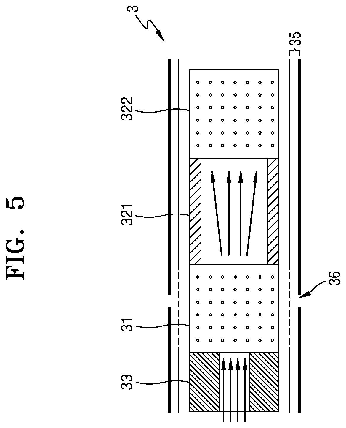
[0045] According to another embodiment, the first segment 321 may be manufactured by weaving a polymer fiber. In this case, a fiber formed of polymer may be coated with a flavored liquid. Alternatively, the first segment 321 may be manufactured by weaving together an additional fiber coated with a flavored liquid and a fiber formed of polymer. Alternatively, the first segment 321 may be formed by a crimped polymer sheet. As a result, a surface area contacting the aerosol may be increased. Therefore, an aerosol cooling effect of a cooling structure may be further improved.
[0046] For example, polymer may be formed of a material selected from the group consisting of polyethylene (PE), polypropylene (PP), polyvinyl chloride (PVC), polyethylene terephthalate (PET), polylactide (PLA), cellulose acetate (CA), and aluminum foil.
[0047] As the first segment 321 may be formed by the woven polymer fiber or the crimped polymer sheet, the first segment 321 may include a single channel or a plurality of channels extending in a longitudinal direction. Here, a channel refers to a passage through which a gas (e.g., air or an aerosol) passes.
[0048] The first segment 321 may include a thread including a volatile flavor component. Here, the volatile flavor component may be menthol but is not limited thereto. The second segment 322 of the filter rod 32 may be a cellulose acetate filter. A length of the second segment 322 may be an appropriate length within a range of about 4 mm to about 20 mm. For example, the length of the second segment 322 may be about 14 mm or about 12 mm, but is not limited thereto.
[0049] In a process of manufacturing the second segment 322, a flavor may be provided by injecting a flavored liquid onto the second segment 322. Alternatively, an additional fiber coated with a flavored liquid may be inserted into the second segment 322. An aerosol generated in the tobacco rod 31 is cooled by passing through the first segment 321, and the cooled aerosol is delivered to the user through the second segment 322. Therefore, when a flavored liquid is added to the second segment 322, an effect of enhancing the persistence of a flavor delivered to the user may be generated.
[0050] The front-end plug 33 may be an air flow delivery element that delivers a gas from a front end thereof to a rear end thereof by providing a path through which the gas discharged from the tobacco rod 31 moves.
[0051] The front-end plug 33 may include an empty space through which a gas may move.
[0052] The empty space may be a hollow or a passage having a polygonal cross section and extending in a longitudinal direction. Alternatively, the empty space may be a plurality of holes in the front-end plug 33 formed of a porous material.
[0053] The porosity of the front-end plug 33 may be variously determined by the empty space. The porosity may indicate a proportion of an area occupied by the empty space in a total cross-sectional area of the front-end plug 33. The porosity may be designed in consideration of a cooling effect of an air flow and the amount of nicotine transfer.
[0054] The empty space and the porosity may be designed in various shapes and dimensions, and embodiments thereof will be described in more detail later with reference to FIG. 6.
[0055] The porosity of the front-end plug 33 may be less than the porosity of the first segment 321. As such, an air flow exiting the front-end plug 33 may expand while passing through the first segment 321, thereby cooling the air flow and increasing the amount of nicotine transfer. This will be described in more detail later with reference to FIG. 5.
[0056] The front-end plug 33 may be formed of cellulose acetate. Also, as needed, the front-end plug 33 may include at least one channel, and a cross-sectional shape of the channel may be formed in various shapes.
[0057] FIG. 2 is a perspective view of a cigarette according to another embodiment.
[0058] The above description with reference to FIG. 1 may be applied to a cigarette 3 that will be described with reference to FIG. 2. FIG. 2 illustrates additional features which may be included in the cigarette 3 described above with reference to FIG. 1.
[0059] A wrapper 35 may include a plurality of wrappers surrounding respective segments.
[0060] For example, a front-end plug 33 may be packaged by a first wrapper 351, a tobacco rod 31 may be packaged by a second wrapper 352, a first segment 321 may be packaged by a third wrapper 353, and a second segment 322 may be packaged by a fourth wrapper 354. Also, the entire cigarette 3 may be repackaged by a fifth wrapper 355.
[0061] The first wrapper 351 may be a combination of general plug wrap paper and metal foil such as aluminum foil. The second wrapper 352 and the third wrapper 353 may be formed of general plug wrap paper. For example, the second wrapper 352 and the third wrapper 353 may be porous plug wrap paper or non-porous plug wrap paper.
[0062] The wrapper 35 may have at least one perforation 36 formed therein. Air outside the cigarette 3 may be introduced into the cigarette 3 through the perforation 36 formed in the wrapper 35.
[0063] The perforation 36 may be formed in various locations. For example, the perforation 36 may be formed in the fifth wrapper 355. Air introduced through the fifth wrapper 355 may be introduced into the cigarette 3 by passing through an inner wrapper surrounded by the fifth wrapper 355.
[0064] As another example, the perforation 36 may be formed in an area surrounding a filter rod 32. In detail, the perforation 36 may be formed in an area surrounding the first segment 321. Here, air introduced through the perforation 36 may cool heated air and cool a surface of the filter rod 32 before the heated air passing through the tobacco rod 31 reaches the mouth of a user.
[0065] The perforation 36 may be formed in various numbers. For example, three perforations 36 may be formed or nine perforations 36 may be formed. Here, a distance between the perforations 36 may be constant or the perforations 36 may be formed at different distances with a preset pattern.
[0066] FIGS. 3 and 4 are diagrams illustrating examples in which a cigarette is inserted into an aerosol generating apparatus.
[0067] Referring to FIG. 3, the aerosol generating device 1 may include a battery 11, a controller 12, and a heater 13. Referring to FIG. 4, the aerosol generating device 1 may further include a vaporizer 14. Also, the cigarette 3 may be inserted into an inner space of the aerosol generating device 1.
[0068] FIGS. 3 through 4 only illustrate components of the aerosol generating device 1, which are particularly related to the present embodiment. Therefore, it will be understood by one of ordinary skill in the art related to the present embodiment that other general-purpose components may be further included in the aerosol generating device 1, in addition to the components illustrated in FIGS. 3 through 4.
[0069] Also, FIG. 4 illustrate that the aerosol generating device 1 includes the heater 13. However, as necessary, the heater 13 may be omitted.
[0070] FIG. 3 illustrates that the battery 11, the controller 12, and the heater 13 are arranged in series. Also, FIG. 4 illustrates that the battery 11, the controller 12, the vaporizer 14, and the heater 13 are arranged in series. However, the internal structure of the aerosol generating device 1 is not limited to the structures illustrated in FIGS. 3 through 4. In other words, according to the design of the aerosol generating device 1, the battery 11, the controller 12, the heater 13, and the vaporizer 14 may be differently arranged.
[0071] When the cigarette 3 is inserted into the aerosol generating device 1, the aerosol generating device 1 may operate the heater 13 and/or the vaporizer 14 to generate an aerosol from the cigarette 3 and/or the vaporizer 14. The aerosol generated by the heater 13 and/or the vaporizer 14 is delivered to a user by passing through the cigarette 3.
[0072] As necessary, even when the cigarette 3 is not inserted into the aerosol generating device 1, the aerosol generating device 1 may heat the heater 13.
[0073] The battery 11 may supply power to be used for the aerosol generating device 1 to operate. For example, the battery 11 may supply power to heat the heater 13 or the vaporizer 14, and may supply power for operating the controller 12. Also, the battery 11 may supply power for operations of a display, a sensor, a motor, etc. mounted in the aerosol generating device 1.
[0074] The controller 12 may control overall operations of the aerosol generating device 1. In detail, the controller 12 may control not only operations of the battery 11, the heater 13, and the vaporizer 14, but also operations of other components included in the aerosol generating device 1. Also, the controller 12 may check a state of each of the components of the aerosol generating device 1 to determine whether or not the aerosol generating device 1 is able to operate.
[0075] The controller 12 may include at least one processor. A processor can be implemented as an array of a plurality of logic gates or can be implemented as a combination of a general-purpose microprocessor and a memory in which a program executable in the microprocessor is stored. It will be understood by one of ordinary skill in the art that the processor can be implemented in other forms of hardware.
[0076] The heater 13 may be heated by the power supplied from the battery 11. For example, when the cigarette 3 is inserted into the aerosol generating device 1, the heater 13 may be located outside the cigarette 3. Thus, the heated heater 13 may increase a temperature of an aerosol generating material in the cigarette 3.
[0077] The heater 13 may include an electro-resistive heater. For example, the heater 13 may include an electrically conductive track, and the heater 13 may be heated when currents flow through the electrically conductive track. However, the heater 13 is not limited to the example described above and may include all heaters which may be heated to a desired temperature. Here, the desired temperature may be pre-set in the aerosol generating device 1 or may be set as a temperature desired by a user.
[0078] As another example, the heater 13 may include an induction heater. In detail, the heater 13 may include an electrically conductive coil for heating a cigarette in an induction heating method, and the cigarette may include a susceptor which may be heated by the induction heater.
[0079] For example, the heater 13 may include a tube-type heating element, a plate-type heating element, a needle-type heating element, or a rod-type heating element, and may heat the inside or the outside of the cigarette 3, according to the shape of the heating element.
[0080] Also, the aerosol generating device 1 may include a plurality of heaters 13. Here, the plurality of heaters 13 may be inserted into the cigarette 3 or may be arranged outside the cigarette 3. Also, some of the plurality of heaters 13 may be inserted into the cigarette 3 and the others may be arranged outside the cigarette 3. In addition, the shape of the heater 13 is not limited to the shapes illustrated in FIGS. 3 through 4 and may include various shapes.
[0081] Referring to FIG. 4, the aerosol generating apparatus 1 may further include the vaporizer 14.
[0082] The vaporizer 14 may generate an aerosol by heating a liquid composition and the generated aerosol may pass through the cigarette 3 to be delivered to a user. In other words, the aerosol generated via the vaporizer 14 may move along an air flow passage of the aerosol generating device 1 and the air flow passage may be configured such that the aerosol generated via the vaporizer 14 passes through the cigarette 3 to be delivered to the user.
[0083] For example, the vaporizer 14 may include a liquid storage, a liquid delivery element, and a heating element, but it is not limited thereto. For example, the liquid storage, the liquid delivery element, and the heating element may be included in the aerosol generating device 1 as independent modules.
[0084] The liquid storage may store a liquid composition. For example, the liquid composition may be a liquid including a tobacco-containing material having a volatile tobacco flavor component, or a liquid including a non-tobacco material. The liquid storage may be formed to be attached to and detached from the vaporizer 14, or may be formed integrally with the vaporizer 14.
[0085] For example, the liquid composition may include water, a solvent, ethanol, plant extract, spices, flavorings, or a vitamin mixture. The spices may include menthol, peppermint, spearmint oil, and various fruit-flavored ingredients, but are not limited thereto. The flavorings may include ingredients capable of providing various flavors or tastes to a user. Vitamin mixtures may be a mixture of at least one of vitamin A, vitamin B, vitamin C, and vitamin E, but are not limited thereto. Also, the liquid composition may include an aerosol forming substance, such as glycerin and propylene glycol.
[0086] The liquid delivery element may deliver the liquid composition of the liquid storage to the heating element. For example, the liquid delivery element may be a wick such as cotton fiber, ceramic fiber, glass fiber, or porous ceramic, but is not limited thereto.
[0087] The heating element is an element for heating the liquid composition delivered by the liquid delivery element. For example, the heating element may be a metal heating wire, a metal hot plate, a ceramic heater, or the like, but is not limited thereto. In addition, the heating element may include a conductive filament such as nichrome wire and may be positioned as being wound around the liquid delivery element. The heating element may be heated by a current supply and may transfer heat to the liquid composition in contact with the heating element, thereby heating the liquid composition. As a result, aerosol may be generated.
[0088] For example, the vaporizer 14 may be referred to as a cartomizer or an atomizer, but it is not limited thereto.
[0089] The aerosol generating device 1 may further include general-purpose components in addition to the battery 11, the controller 12, the heater 13, and the vaporizer 14. For example, the aerosol generating device 1 may include a display capable of outputting visual information and/or a motor for outputting haptic information. Also, the aerosol generating device 1 may include at least one sensor Also, the aerosol generating device 1 may be formed as a structure where, even when the cigarette 3 is inserted into the aerosol generating device 1, external air may be introduced or internal air may be discharged.
[0090] Although not illustrated in FIGS. 3 through 4, the aerosol generating device 1 and an additional cradle may form together a system. For example, the cradle may be used to charge the battery 11 of the aerosol generating device 1. Alternatively, the heater 13 may be heated when the cradle and the aerosol generating device 1 are coupled to each other.
[0091] The cigarette 3 may be similar as a general combustive cigarette. For example, the cigarette 20000 may be divided into the tobacco rod 31 including an aerosol generating material and the filter rod 32 including a filter, etc. The filter rod 32 of the cigarette 3 may also include an aerosol generating material. For example, an aerosol generating material made in the form of granules or capsules may be inserted into the filter rod 32.
[0092] The entire tobacco rod 31 may be inserted into the aerosol generating device 1, and the filter rod 32 may be exposed to the outside. Alternatively, only a portion of the tobacco rod 31 may be inserted into the aerosol generating device 1, or the entire tobacco rod 31 and a portion of the filter rod 32 may be inserted into the aerosol generating device 1. The user may puff aerosol while holding the filter rod 32 by the mouth of the user. In this case, the aerosol is generated by the external air passing through the tobacco rod 31, and the generated aerosol passes through the filter rod 32 and is delivered to the user's mouth.
[0093] For example, the external air may flow into at least one air passage formed in the aerosol generating device 1. For example, opening and closing of the air passage and/or a size of the air passage may be adjusted by the user. Accordingly, the amount and quality of the aerosol may be adjusted by the user. As another example, the external air may flow into the cigarette 3 through at least one hole formed in a surface of the cigarette 3.
[0094] FIG. 5 is a cross-sectional view taken along line A-A' of FIG. 1, illustrating a flow of air passing through a cigarette of FIG. 1.
[0095] Referring to FIG. 5, when the user smokes by using the cigarette 3, air may flow into the cigarette 3 through the front-end plug 33, carry a generated aerosol while passing through the tobacco rod 31, and reach the mouth of the user by passing through the first segment 321 and the second segment 322 of the filter rod 32.
[0096] The porosity of the first segment 321 may be greater than the porosity of the front-end plug 33. As such, a gas including air and mainstream vapor which exits the front-end plug 33 and enters the first segment 321 may instantaneously expand in volume. Therefore, the gas may be cooled while expanding. Also, the gas may diffuse in a radial direction of the cigarette 3 while entering the first segment 321. Here, the directionality of an air flow moving downstream is reduced, which makes the gas stay longer in the first segment 321. As a result, a cooling effect may be improved.
[0097] As a difference in the porosity between the front-end plug 33 and the first segment 321 becomes greater, the cooling effect of the gas described above may be improved. In other words, as the porosity of the first segment 321 becomes greater, the cooling effect of the gas described above may be improved.
[0098] For example, when the first segment 321 is a tube type having a hollow, the porosity increases as an inner diameter increases, thereby improving a cooling effect of a gas. When the front-end plug 33 is a tube type, to the extent that the inner diameter of the first segment 321 is greater than an inner diameter of the front-end plug 33, the cooling effect of the gas may be improved.
[0099] Also, the porosity of the front-end plug 33 and the first segment 321 may affect the draw resistance with respect to an air flow and the amount of nicotine carried by the air flow. As the porosity of the first segment 321 becomes greater, the amount of air introduced may increase, and the draw resistance may decrease. As a result, the transfer amount of nicotine-including aerosol generated in the tobacco rod 31 may increase.
[0100] Therefore, the porosity, the inner diameter values, and the like of the front-end plug 33 and the first segment 321 may be determined in consideration of the draw resistance, the transfer amount of aerosol, and the cooling effect of the gas.
[0101] FIG. 6 is a cross-sectional view of a cigarette of FIG. 1 respectively taken along lines B-B' and C-C' of FIG. 1. The cross sections of FIGS. 6A and 6B are merely examples of cross sections of the cigarette 3 but are not limited thereto.
[0102] FIG. 6A is a cross-sectional view of the cigarette 3 taken along line B-B'. Referring to FIG. 6A, a cross section of the cigarette 3 may include an empty space in which a plurality of slit-shaped or rod-shaped spaces are combined. The cross section of FIG. 6A may be a cross section of the front-end plug 33.
[0103] For example, the empty space may have a Y shape in which three slit-shaped or rod-shaped empty spaces having different extension directions are combined.
[0104] The porosity of the cross section of the cigarette 3 may vary according to the number, thickness, and length of the slit-shaped or rod-shaped empty spaces. For example, a total cross-sectional area of the cigarette 3 may be 38.5 mm.sup.2, and a cross-sectional area of the empty space may be 10.89 mm.sup.2. Here, the porosity of the cigarette 3 may be 28.3%.
[0105] As another example, the total cross-sectional area of the cigarette 3 may be 38.5 mm.sup.2, and the cross-sectional area of the empty space may be 8.21 mm.sup.2. Here, the porosity of the cross section of the cigarette 3 may be 21.3%. As another example, the total cross-sectional area of the cigarette 3 may be 38.5 mm.sup.2, and the cross-sectional area of the empty space may be 5.75 mm.sup.2. Here, the porosity of the cross section of the cigarette 3 may be 14.9%. In other words, referring to FIG. 6A, the porosity of the cross section of the cigarette 3 may be greater than or equal to about 10% and less than about 30%.
[0106] The cross section of FIG. 6A is merely an example of the cross section of the cigarette 3, and embodiments are not limited thereto. For example, the cross section of the cigarette 3 may include one, two, four or more slit-shaped or rod-shaped empty spaces. Here, the porosity may increase with an increase in the number of slit-shaped or rod-shaped empty spaces.
[0107] FIG. 6B is a cross-sectional view of the cigarette 3 taken along line C-C'. Referring to FIG. 6B, the cross section of the cigarette 3 may have a tube shape having a hollow formed therein. FIG. 6B may illustrate, for example, a cross section of the first segment 321.
[0108] An inner diameter of the hollow may be designed to provide preset porosity. The porosity may increase with an increase in the inner diameter of the hollow and may decrease with a decrease in the inner diameter of the hollow.
[0109] For example, a total diameter of the cigarette 3 may be within a range of about 5 mm to about 9 mm. In detail, the diameter of the cigarette 3 may be about 7 mm to about 7.4 mm.
[0110] Here, the inner diameter of the hollow may be in a range of 3.0 mm and 4.5 mm. Preferably, the inner diameter of the hollow may be greater than or equal to 3.8 mm. More preferably, the inner diameter of the hollow may be greater than or equal to 4.0 mm.
[0111] As a result, the inner diameter of the hollow may be greater than or equal to 50% of the total diameter of the cigarette 3. In detail, the inner diameter of the hollow may be greater than or equal to 55% of the total diameter of the cigarette 3.
[0112] A total cross-sectional area of the cigarette 3 may be 38.5 mm.sup.2, and a cross-sectional area of an empty space due to the hollow may be 13.85 mm.sup.2. Here, the porosity of the cross section of the cigarette 3 may be greater than or equal to 30%. In detail, the porosity of the cross section of the cigarette 3 may be 36.0%.
[0113] As described above with reference to FIGS. 6A and 6B, the porosity of the cross section of the cigarette 3 may be differently designed according to a cross-sectional shape of the cigarette 3. For example, the first segment 321 may have a hollow-shaped cross section with a porosity greater than or equal to 30% as illustrated in FIG. 6B, and the front-end plug 33 may have a cross section including a Y-shaped empty space having a porosity greater than or equal to 10% and less than 30% as illustrated in FIG. 6A. In other words, a ratio of the porosity of the first segment 321 to the porosity of the front-end plug 33 may be greater than or equal to 1 and less than 3.
[0114] FIG. 7 is a view illustrating a location where a temperature of mainstream gas and a surface temperature of a cigarette are measured in the cigarette, according to an embodiment. FIG. 7A is a cross-sectional view of a cigarette 3 cut in a longitudinal direction, and FIG. 7B is a perspective view of the cigarette 3. A perforation 36 may be located in the wrapper surrounding a first segment 321.
[0115] Table 1 below shows data about a mainstream gas temperature of the cigarette 3, a surface temperature of the cigarette 3, and the amount of nicotine transfer, which are measured by varying a ratio of porosity of a first segment 321 to porosity of a front-end plug 33. As illustrated in FIG. 7A, the first segment 321 and a second segment 322 are adjacent to each other, and a mainstream gas temperature is measured in area A1 through which mainstream gas passes. The mainstream gas temperature may be measured through a temperature sensor. As illustrated in 7B, a surface temperature is measured in an area A2 of the center of a surface of the second segment 322. The surface temperature may be measured through a thermal imaging analysis.
TABLE-US-00001 TABLE 1 Experimental Experimental Experimental Classification Example #1 Example #2 Example #3 First Segment Porosity (%) 12.8 23.6 36.0 Front-end Plug Porosity (%) 28.3 Cigarette Surface 50.0 53.0 53.0 Temperature (.degree. C.) Mainstream Smoke 62.0 58.6 56.2 Temperature (.degree. C.) Nicotine Transfer Amount 0.60 0.66 0.71 (mg/cigarette)
[0116] An empty space cross-sectional area of the front-end plug 33 is 10.89 mm.sup.2, and the porosity thereof is 28.3%. In each experimental example, the empty space cross-sectional area of the front-end plug 33 is 10.89 mm.sup.2, and thus, the porosity of a cross section of the front-end plug 33 is maintained at 28.3%. In the first experimental example, the first segment 321 may have a tube shape having a hollow, and an outer diameter of the first segment 321 may be about 7 mm to about 7.4 mm. An inner diameter of the first segment 321 is 2.5 mm. A ratio of the inner diameter of the first segment 321 to the outer diameter of the first segment 321 is 34%. An empty space cross-sectional area of the first segment 321 is 4.91 mm.sup.2, and thus, the porosity of a cross section of the first segment 321 is 12.8%.
[0117] In the second experimental example, the inner diameter of the first segment 321 is 3.4 mm. A ratio of the inner diameter of the first segment 321 to the outer diameter of the first segment 321 is 46%. The empty space cross-sectional area of the first segment 321 is 9.07 mm.sup.2, and thus, the porosity of the cross section of the first segment 321 is 23.6%.
[0118] In the third experimental example, the inner diameter of the first segment 321 is 4.2 mm. A ratio of the inner diameter of the first segment 321 to the outer diameter of the first segment 321 is 56%. The empty space cross-sectional area of the first segment 321 is 13.85 mm.sup.2, and thus, the porosity of the cross section of the first segment 321 is 36.0%.
[0119] Referring to Table 1 above, as described above with reference to FIG. 5, as the porosity of the first segment 321 increases, the surface temperature and the mainstream gas temperature of the cigarette 3 decrease, and the amount of nicotine transfer increases.
[0120] In particular, when the porosity of the front-end plug 33 is less than 30% and the porosity of the first segment 321 is greater than or equal to 30%, the mainstream gas temperature may be as low as 56.2.degree. C., and the amount of nicotine transfer may be as high as 0.71 mg/cigarette.
[0121] Those of ordinary skill in the art related to the present embodiments may understand that various changes in form and details can be made therein without departing from the scope of the characteristics described above. The disclosed methods should be considered in a descriptive sense only and not for purposes of limitation. The scope of the present disclosure is defined by the appended claims rather than by the foregoing description, and all differences within the scope of equivalents thereof should be construed as being included in the present disclosure.
* * * * *
D00000
D00001
D00002
D00003
D00004
D00005
D00006
D00007
XML
uspto.report is an independent third-party trademark research tool that is not affiliated, endorsed, or sponsored by the United States Patent and Trademark Office (USPTO) or any other governmental organization. The information provided by uspto.report is based on publicly available data at the time of writing and is intended for informational purposes only.
While we strive to provide accurate and up-to-date information, we do not guarantee the accuracy, completeness, reliability, or suitability of the information displayed on this site. The use of this site is at your own risk. Any reliance you place on such information is therefore strictly at your own risk.
All official trademark data, including owner information, should be verified by visiting the official USPTO website at www.uspto.gov. This site is not intended to replace professional legal advice and should not be used as a substitute for consulting with a legal professional who is knowledgeable about trademark law.