Smoking Product Humidification Apparatus And Method
Alexander; Austin
U.S. patent application number 17/028861 was filed with the patent office on 2021-01-07 for smoking product humidification apparatus and method. The applicant listed for this patent is Austin Alexander. Invention is credited to Austin Alexander.
| Application Number | 20210000173 17/028861 |
| Document ID | / |
| Family ID | |
| Filed Date | 2021-01-07 |


View All Diagrams
| United States Patent Application | 20210000173 |
| Kind Code | A1 |
| Alexander; Austin | January 7, 2021 |
SMOKING PRODUCT HUMIDIFICATION APPARATUS AND METHOD
Abstract
A lid and sleeve system that creates a zero maintenance humidity controlled, protective environment within a cigar tube is disclosed. This invention incorporates two-way humidity control technology while adding superior protection as well as optimal air circulation in an optionally transparent tube, designed for but not limited to the disposable retail packaging of a cigar.
| Inventors: | Alexander; Austin; (Los Angeles, CA) | ||||||||||
| Applicant: |
|
||||||||||
|---|---|---|---|---|---|---|---|---|---|---|---|
| Appl. No.: | 17/028861 | ||||||||||
| Filed: | September 22, 2020 |
Related U.S. Patent Documents
| Application Number | Filing Date | Patent Number | ||
|---|---|---|---|---|
| 15798318 | Oct 30, 2017 | 10779567 | ||
| 17028861 | ||||
| 62414118 | Oct 28, 2016 | |||
| Current U.S. Class: | 1/1 |
| International Class: | A24F 25/02 20060101 A24F025/02; A24F 15/12 20060101 A24F015/12; A24F 15/20 20060101 A24F015/20; B65D 85/12 20060101 B65D085/12; B65D 81/05 20060101 B65D081/05 |
Claims
1. An apparatus for packaging and storing an elongated smoking product comprising: a. a hollow container vessel that is open at least at one end and is sized to contain the smoking product and having a diameter relative to the diameter of the smoking product that is sufficient to provide space surrounding the smoking product; b. a sealing cap assembly comprising: i. a sealing lid; ii. an upper locating member affixed to an end of the sealing lid wherein the upper locating member is configured to accept one end of the smoking product so as to be sufficiently centered within the hollow container vessel so as to provide space surrounding the smoking product; whereby the smoking product is protected against physical damage by the upper locating member.
2. The apparatus of claim 1 wherein the smoking product is a cigar.
3. The apparatus of claim 1 wherein the upper locating member further comprises flexible material having an opening formed therein to receive the one end of the smoking product and to hold the one end in place.
4. The apparatus of claim 3 wherein the flexible material comprises one or more of plastic, elastic, polymer, silicone, rubber, cork, or adequately interwoven organic and nonorganic materials such as but not limited to cellulose containing materials, fiber, rayon, felt, polyester, cotton, wool, metallic wool.
5. The apparatus of claim 3 wherein the flexible material comprises foam.
6. The apparatus of claim 1 wherein the upper locating member comprises a spring member formed on an interior wall thereof that deflects to receive the one end of the smoking product and is biased toward a center of the lid to retain the smoking product in place.
7. The apparatus of claim 6 wherein the spring member comprises a metal member formed on the interior wall coupled at a top and bottom of the interior wall and having a shape that extends away from the top midway and then extends towards the bottom, with an open space behind the spring member.
8. The apparatus of claim 1 wherein the lid comprises a plurality of tabs extending from a bottom of an interior wall of the lid, such that the tabs can be deflected toward the interior wall when the one end of the smoking product is inserted therein.
9. The apparatus of claim 3 wherein the flexible material comprises cardboard.
Description
RELATED APPLICATION
[0001] This application claims the benefit of U.S. Provisional Application Ser. No. 62/414,118 filed on Oct. 28, 2016 and is a continuation-in-part of U.S. patent application Ser. No. 15/798,318 filed on Oct. 30, 2017, both of which are incorporated by reference herein in their entirety.
FIELD OF THE INVENTION
[0002] The invention relates generally to the field of smoking product packaging and accessories.
BACKGROUND
[0003] Cigar storage humidity control can be found in US published patent applications; US 2015/0201673; US 2012/0031780; US 2008/0245685 and in US issued patents; U.S. Pat. Nos. 8,342,185; 5,957,277; 5,957,380; 5,893,454; 6,298,857; 5,816,264; 5,936,178; 3,771,535; 2,911,983; 2,296,830; 1,997,629; 1,699,090; 1,619,306; 1,366,283 U.S. Pat. Nos. 5,749,461; 6,279,581; 8,602,210, The content of all of the foregoing published applications and patents is incorporated herein by reference.
[0004] Other content can be found in US published applications US 2015/0021217; and US 2015/0328584; and in US issued U.S. Pat. Nos. 8,540,075; 8,087,645; 7,565,969; 6,157,306; 6,157,306; 6,006,903; 5,881,868; 5,829,581; 5,535,763; 5,277,315; 5,277,315; 5,037,459; 5,011,009; 4,930,526; 3,137,303; 2,740,683. The content of all of the foregoing published applications and patents is incorporated herein by reference.
BRIEF DESCRIPTION OF THE DRAWINGS
[0005] FIG. 1 is an assembled view of the smoking product humidifying apparatus with a cigar in the storage position.
[0006] FIG. 2 is a view of the cigar humidifying apparatus with the sealing lid assembly disassembled.
[0007] FIG. 3a depicts the humidity control chamber assembly.
[0008] FIG. 3b is a cross section view of the sealing lid assembly.
[0009] FIG. 3c is a cross section view of an alternative embodiment of the upper locating member using a winged receiving cap.
[0010] FIG. 3d is a cross section view of an alternative embodiment of the upper locating member using a winged receiving cap shown with a received cigar.
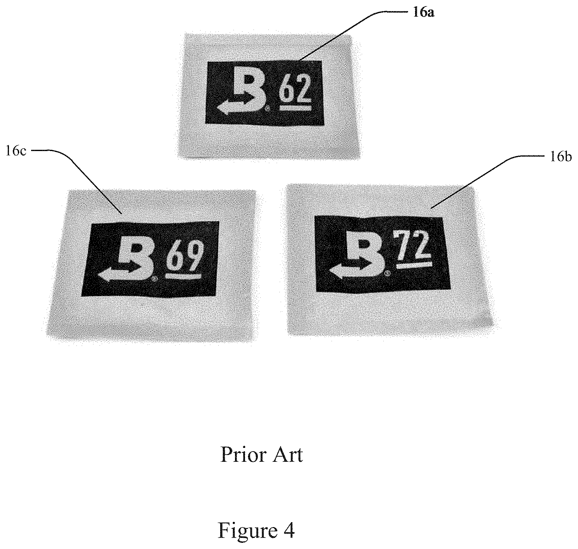
[0011] FIG. 4 shows 3 versions of the Boveda humidity control packets.
[0012] FIG. 5a is a side view of an embodiment of the upper locating member looking in from below
[0013] FIG. 5b is a side view of an embodiment of the upper locating member looking in from above.
[0014] FIG. 5c is a top view of an embodiment of the upper locating member.
[0015] FIG. 5b is a top view of the upper locating member.
[0016] FIG. 5d is a top view of the upper locating member embodiment with flexible wings.
[0017] FIG. 6a is a top view of the stabilizing disc.
[0018] FIG. 6b a side view of the stabilizing disc with upright sleeve.
[0019] FIG. 6c is a cross section view of the bottom portion of the humidifying apparatus with upright sleeve and a cigar in stabilized position.
[0020] FIG. 6d is a cross section view of the bottom portion of the humidifying apparatus with upright sleeve and a cigar in stabilized position.
[0021] FIG. 6e is a cross section view of the bottom portion of the humidifying apparatus with upright sleeve and a cigar in stabilized position.
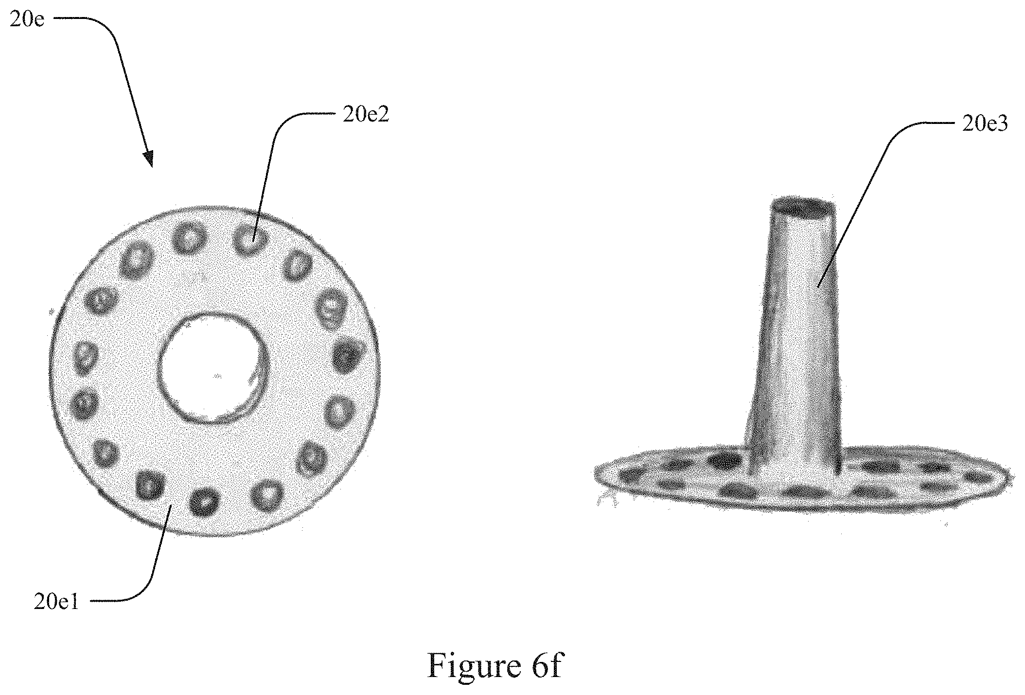
[0022] FIG. 6f shows the top and side views of an alternative stabilizing disc for cigars with a hole in the mouthpiece.
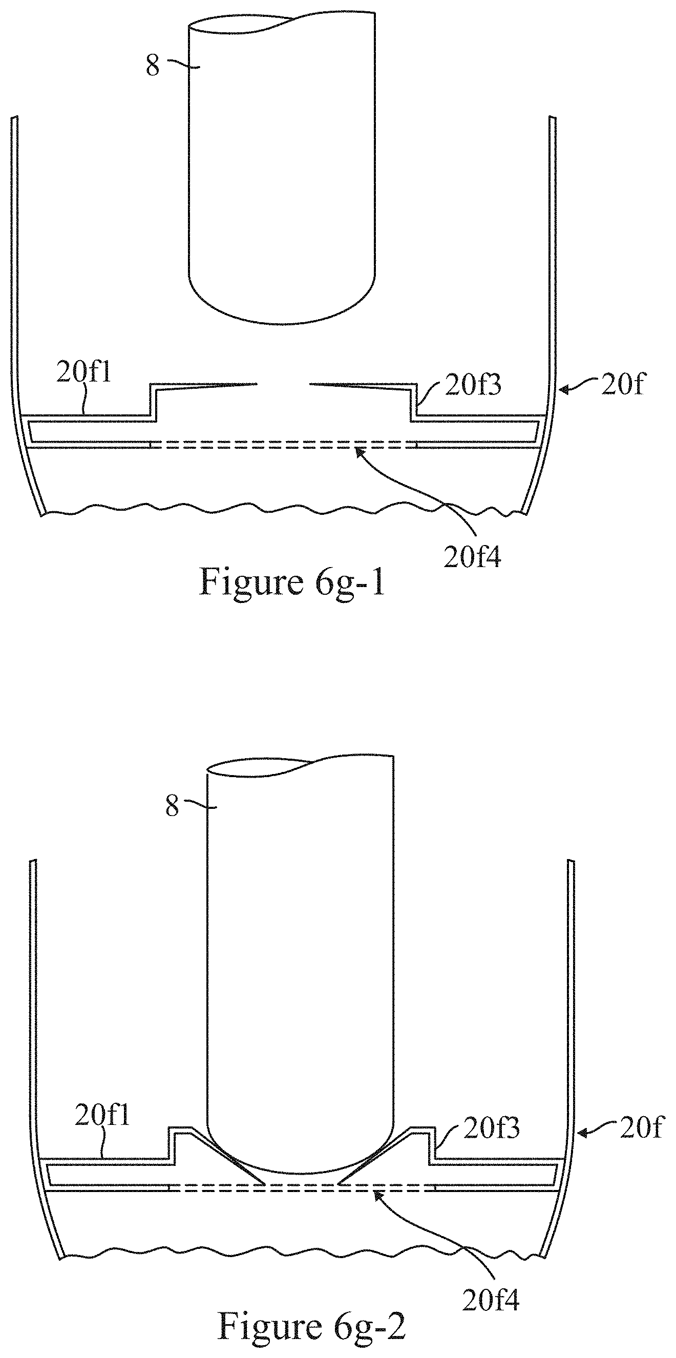
[0023] FIG. 6g-1 is a cross section view of an alternative winged lower locating member or stabilizing disc ready for lower of the smoking product
[0024] FIG. 6g-2 is a cross section view of an alternative winged lower locating member or stabilizing disc with the smoking product in place
[0025] FIG. 6h is a top view of an alternative winged lower locating member or stabilizing disc.
[0026] FIG. 7a shows a side view of the combination stabilizing disc with cutter assembly.
[0027] FIG. 7b shows a top view of the combination stabilizing disc with cutter assembly.
[0028] FIG. 7c shows a top view of the combination stabilizing disc with cutter assembly shown with the blade partially closed.
[0029] FIG. 8a shows a top view of the cigar stabilizer with cutter, top plate.
[0030] FIG. 8b shows a top view of the cigar stabilizer with cutter, bottom plate.
[0031] FIG. 8c shows a top view of the cigar stabilizer with cutter, blade plate.
[0032] FIG. 9a shows a side view of an alternative embodiment of the combination stabilizing disc with cutter assembly.
[0033] FIG. 9b shows a top view of an alternative embodiment of the combination stabilizing disc with cutter assembly.
[0034] FIG. 9c shows a top view of an alternative embodiment of the combination stabilizing disc with cutter assembly shown with the blade partially closed.
[0035] FIG. 10a shows a top view of an alternative embodiment of the cigar stabilizer with cutter, top plate.
[0036] FIG. 10b shows a top view of an alternative embodiment of the cigar stabilizer with cutter, bottom plate.
[0037] FIG. 10c shows a top view of an alternative embodiment of the cigar stabilizer with cutter, blade plate.
[0038] FIG. 11A shows an example of an embodiment with a single attachment point for the cigar.
[0039] FIG. 11B shows the embodiment of FIG. 11A with a humidifying apparatus.
[0040] FIG. 12A illustrates an embodiment of a cigar holding apparatus in an embodiment.
[0041] FIG. 12B illustrates the apparatus of FIG. 12A in use.
[0042] FIGS. 13A and 13B illustrate an embodiment of a cigar holding apparatus.
[0043] FIG. 14 illustrates an embodiment of a cigar holding apparatus integrated into a humidity control apparatus in an embodiment.
[0044] FIG. 15 illustrates an alternative stabilizing disc in an embodiment.
DETAILED DESCRIPTION
[0045] Maintaining the humidity of a storage vessel for smoking products such as cigars is important for preserving the quality of stored cigars. Disclosed and described herein is a humidity controlled smoking product containing apparatus and a method of providing humidity control for a smoking product. The described embodiments present a low-cost, zero-maintenance, lid & sleeve system which provides a humidity controlled, protective tube for storing or packaging smoking products including cigars suspended within the tube.
[0046] While the following description uses the context of cigars as the product being protected, it is understood that the description is applicable to all smoking products of the type having any shape, including an elongated cylindrical, conical, or tapered exterior surface, with a burning end and an inhaling end.
[0047] The apparatus as described keeps the cigar centrally located within the tube so that the circulation space around it is uniform thereby allowing controlled continuous flow of the humidity preserving gas and also protecting the cigar from damage such as may be caused by transporting or simply a user carrying it. This is done by holding the cigar in a central position inside the tube by a holding means at each end of the cigar and where the holding means are carefully shaped to accept the shape of the cigar sufficiently holding it steady but preventing damage to the cigar. It is also noted that in the cigar world per se, collecting and preserving is a business and hobby. The present descriptions allow for protection of cigar bands, the presence and quality condition of which are important to the value of collectable cigars. Also, in that context, marketing benefit is obtained by attractive visual access to the cigar, rather than covering it with packing material. Such packing material is usually made of plastic foam or compressible organic material and commonly inserted into cigar tubes between the cap and cigar to immobilize the smoking product. It is physically obstructive and annoying for consumers to remove said packing material in order to access the cigar. Said packing material is also visually intrusive, which affects optimal visual comprehension and overall marketability of the entire smoking product. Retailers commonly use this packing material to immobilize the cigar, which protects the cigar from internal impact with the tube. It also prevents the cigar band from becoming dislocated from the manufacture's originally intended positioning.
[0048] Currently available disposable cigar tubes do not maintain a zero-maintenance humidity controlled environment. In a low humidity environment cigar tobacco will dry out and the quality of the cigar will deteriorate. Two-way humidity control packets have been developed by Boveda Manufacturing Company of Minnetonka, Minn. These packets cannot be simply inserted inside a cigar tube with a cigar, as the cigar itself would stifle the humidity controlled air by blocking its consistent circulation inside such a tight space. The packet could also become easily stuck inside the tube, damaging the fragile cigar material with internal impact such as by crushing the packet against the cigar. The unsightly Boveda packet also detracts from the marketing of cigars when presenting cigars in clear tube packages.
[0049] Available humidor equipped tubes are not designed to be disposable, they do not incorporate maintenance free 2-way humidity control technology and they do not suspend cigars in a centralized position. In contrast the disclosed storage tube suspension system not only optimally protects the cigar but also allows even circulation of humidity controlled air to constantly flow around the entire cigar.
[0050] If one were to simply place a 2-way humidity control packet inside of a standard cigar tube it could easily become stuck, inhibit air circulation, make for poor visual marketing and pose a threat of physical damage to the delicate cigar material, via free floating internal impact. The only currently available disposable retail cigar packaging that does incorporate 2-way humidity control technology comes in the form of a foil-lined sealed plastic bag that holds a free floating cigar and free floating humidity control packet inside the pouch together. That system offers inconsistent airflow and inadequate protection of the cigar itself, from both internal & external impacts, while eliminating visual comprehension, thus limiting the cigar's overall marketability. The present invention provides superior protection and optimal air circulation in an optionally transparent tube, designed for but not limited to the disposable retail packaging of a cigar.
[0051] As stated above, disposable cigar tubes do not maintain a zero maintenance humidity controlled environment, so that they lead to a dry and depreciated product. An effective two-way humidity control technology are the packets made by Boveda. however, these packets cannot be simply inserted inside a cigar tube with a cigar, as the cigar itself would stifle the humidity controlled air by blocking its consistent circulation inside such a tight space. Also, the packet could also become easily stuck inside the tube and or damage the fragile cigar material with internal impact between the packet and the cigar itself. The packet also interferes with the marketing presentation of the cigar if used within a clear tube. The disclosed invention described and claimed here solves this problem.
[0052] As described below in more detail with respect to the drawings the present cigar humidity control apparatus has a tube for containing a cigar.
[0053] In the disclosed invention, a sealing lid has an attached tapered chamber, which contains two-way humidity control technology. A small circular upper locating member (also referred to as a upper locating member) attached to the bottom of the humidity chamber, slips over the tip of the cigar, keeping it in place on the top, while at the bottom of the tube; there is another stabilizing disk and sleeve component, which holds the opposite end of the cigar securely at the center, in line with the top sleeve. Downward pressure created by sealing the lid pushes these two centralized holding points closer together enough to not crush but centrally immobilize the cigar and suspend it within the tube. The tube circumference itself is larger than the cigar and the tapered humidity control chamber, allowing two-way humidity controlled air to consistently circulate around the entire surface area of the centrally suspended cigar. No currently available system evenly controls the humidification of a cigar with zero maintenance, in a disposable cigar tube; utilizing off-the-shelf two-way humidification packets. Current use of the packets is problematic as the packets may easily become stuck inside of cigar tubes and detract from visual aspects of marketing. Current use of these packets inside cigar tubes may damage the delicate cigar material via free floating impact between the packet and the cigar itself. The current invention allows for even humidification while eliminating the obstacle of packet removal as well as the packet's unappealing visual aesthetic, and securely protects the cigar from any potential internal impact from the packet and tube walls. The current invention also effectively immobilizes the cigar, which alleviates the need for retailers to insert packing materials into the tube between the cap and the cigar. Such packing material is usually made of plastic foam or compressible organic material. It is physically obstructive and annoying for consumers to remove said packing material in order to access the cigar. Packing is also visually intrusive, which effects optimal visual comprehension and overall marketability of the entire smoking product. Retailers commonly use this packing material to immobilize the cigar, which protects the cigar from internal impact with the tube. It also prevents the cigar band from becoming dislocated from its originally intended position.
[0054] Available humidor tubes are not designed to be disposable, and they do not provide maintenance free two-way humidity control technology, while suspending cigars in a centralized position. The only currently available disposable retail cigar packaging that does incorporate two-way humidity control technology comes in the form of a foil-lined sealed plastic bag that holds a free floating cigar and free floating humidity control packet inside the pouch together. This foil bag system suffers from inconsistent airflow and inadequate protection of the cigar itself from both internal and external impacts. The foil bag system also prevents viewing the cigar, limiting the overall marketability.
[0055] Available humidor tubes are typically bulky and utilize sponges that need to be constantly maintained by the user, leading to inconstant humidity levels and no chance for the functional application of a humidity controlled retail shelf-life environment, which would be optimal for a pre-packaged cigar. The foil-lined, plastic sealed bag utilizing 2-way humidity control technology inadequately protects the delicate cigar from internal impact with the humidity control packet as well as from external impacts and both systems shroud the cigar itself, limiting its overall marketability.
[0056] Various embodiments of the current disclosed invention provide a disposable storage or packaging system for cigars in an optionally transparent tube with air circulation optimized two-way humidity control, physical protection of the cigar and an optional incorporated cutting tool. The miniature incorporated cigar cutter that fits in a cigar tube in an embodiment with a modified version of the stabilizing disk and sleeve component as shown in the drawings to be described below.
[0057] Various embodiments of the cigar humidifying apparatus are described here by a description of the drawings and the identified parts of the apparatus.
[0058] FIG. 1 shows a side view of the humidity controlled smoking product containing apparatus 10 with a cigar 8 with cigar band 8a stored by the apparatus. The humidity controlled smoking product containing apparatus is constructed of the tube 12, a sealing lid assembly 14, and a stabilizing disc 20a (also referred to as the lower locating member) the shown embodiment having an upright sleeve. The sealing lid assembly 14 is constructed of a sealing cap 14a and a breathable humidity control chamber assembly 14b. The sealing cap 14a may be constructed of plastic and may be threaded or non-threaded. Attached to the inside of the sealing cap 14a is the breathable humidity control chamber assembly 14b which is formed by frame 14b1 and a in one embodiment a tapered, plastic mesh 14b2 to allow flow of humidified gas. The breathable humidity control chamber 14b has an upper circular opening 14b3 at the top defined by a circular upper frame rim 14b4 and a lower circular opening 14b5 at the bottom defined by a circular lower frame rim 14b6 at the bottom and has a tapered open area between ribs 14b7 which therefore allow the open area to be covered by a mesh. The diameter of the lower circular opening 14b4 at the bottom is significantly smaller than the sealing cap 14a and is closed at the bottom by the chamber upper locating member 14c. The chamber upper locating member 14c is removably fitted to the bottom of the breathable humidity control chamber 14b such as by friction or interference fit into the circular lower frame rim 14b6. As can be seen, because the breathable humidity control chamber 14b is tapered in form from its top to its bottom, the full area of its open sides is available for flow of the humidifying gas into the tube. See FIG. 3b for a detailed diagram of the sealing lid assembly 14.
[0059] Near the bottom of the tube 12b is the stabilizing disc with upright sleeve 20a. The cigar 8 (with cigar band 8a) is positioned for storage or packaging between the upper locating member 14b3 near the top of the tube 12a and the stabilizing disc with upright sleeve 20a near the bottom of the tube 12b. Humidity control packets 16 as exemplified by the Boveda packets, are contained within the breathable humidity control chamber 14b. As shown by the arrows in FIG. 1, correctly humidified air is allowed to circulate around the entire cigar 8 to optimally preserve the tobacco or organic material composing the cigar. Although the arrows show flow down on one side and up on the other in FIG. 1, the actual flow will be in the nature of randomized flow.
[0060] FIG. 2 shows a partially exploded view of the humidity controlled smoking product containing apparatus 10. This figure shows how the various assemblies and parts as described above fit together. At the top, the sealing lid assembly 14 with the breathable humidity control chamber 14b contains the humidity control packet 16 which is held in the breathable humidity control chamber by the chamber upper locating member 14c. The humidity control packets are typically a water vapor permeable pouch and a thickened saturated salt solution, the Boveda product being exemplary. A cigar 8 with cigar band fits into the bottom of the chamber upper locating member 14c, centering it within the tube 12. The full sealing lid assembly 14 fits into the top of the tube 12a. The cigar 8 fits into the stabilizing disc with upright sleeve 20a, located near the bottom of the tube 12b. The sealing lid assembly 14 may be snapped onto the top of the tube 12 or threaded onto the tube 12 or they may be ribbed for fit, in alternate embodiments, the closure being effective as a hermetic sealing of the entire interior of the tube. To assembly the apparatus with a cigar in place, the cigar is positioned onto the lower stabilizing disc and then the sealing lid assembly 14 is applied to the top of the cigar and tube (which is sized according to a particular cigar). As the lid seals against the top of the tube, the cigar is fixed between the cap sleeve and stabilizing disc, suspending it with almost its entire surface exposed to the humidifying air and is protected from physical damage within the tube. Suspending the smoking product between the upper locating member and stabilizing disc also protects it from any movement, which in the case of a cigar would assist in keeping the cigar band in place during shipping and general movement of the packaging. Suspending the cigar between the upper locating member and the stabilizing disc not only physically protects the smoking product from damage incurred internal impact with the tube walls but it also replaces the need for manufacturers or retailers to stuff their tubes with less than desirable packing materials in order the to keep the cigar band in place.
[0061] FIGS. 3a and 3b show details of the sealing cap assembly. In FIG. 3a, the sealing cap 14a and the breathable humidity control chamber 14b is shown. The breathable humidity control chamber 14b is constructed of a mesh 14b1 which may be a plastic mesh. a, woven thread mesh, or a metallic mesh. The breathable chamber may also include a frame or structural ribs 14b2 which provide a strengthening structure for the chamber walls. Instead of a mesh being integral to the structure of the breathable humidity control chamber 14b, it may be provided by a paper or other mesh fitted around the interior of the humidity control chamber frame.
[0062] FIG. 3b shows a cross section of the sealing lid assembly 14, demonstrating how the various components fit together. The sealing cap 14a of the assembly fits into the top of the cigar tube 12a snuggly to form a seal and as downwardly fitted to securely but gently fit the cigar in place. Shown in the cross-sectional diagram, the breathable humidity control chamber 14b with frame or structural ribs 14b1, mesh 14b2 and chamber upper locating member 14c which closes the bottom of the chamber and holds the cut end of the cigar. Shown is the cap portion 14
[0063] FIGS. 3c and 3d show an alternate embodiment of the chamber upper locating member 14b4 using a winged receiving cap to be further described below. FIG. 3c shows a cross section view of the winged receiving cap 14d prior to the cigar 8 placement. The components of the winged receiving cap 14d include the top mesh 14d1, the sleeve 14d2 and the receiving wings 14d3. FIG. 3d shows a cross section view of the winged receiving cap 14d after the cigar 8 is received by the cap. The components of the winged receiving cap 14d include the top mesh 14d1, the sleeve 14d2 and the receiving wings 14d3. As can be seen, the flexible wings bend inward as the cigar 8 is received, forming holding and centering the cigar.
[0064] FIG. 4 shows images of 3 exemplar Boveda 2-way humidity control packets. The shown packets are marketed by Boveda and as marked, these exemplar packets are designed to maintain the relative humidity at 62% (16a) 69% (16b) and 72% (16c) by either absorbing excess moisture or releasing moisture as needed to maintain the desired level of humidity. Different strains of organic material composing the cigar, including tobacco strains, may be optimally preserved by different humidity control packets.
[0065] FIGS. 5a-5d show depictions of 2 embodiments of the chamber upper locating member 14c. The central portion of each version is a mesh 14c1. FIGS. 5a,5b and 5c show an embodiment of the upper locating member 14b3 allowing the cut end of the cigar to be held inside the sleeve element 14c2. FIG. 5a shows a side perspective view of the upper locating member 14c of the inside of the cap revealed. FIG. 5b shows a side perspective view of the upper locating member 14c of the inside of the cap revealed. Shown are the mesh 14c1 and sleeve 14c2 elements. FIG. 5c shows a bottom view of the upper locating member 14c.
[0066] FIG. 5d shows an alternative embodiment of the chamber upper locating member 14d with cap receiving wings 14d3. Shown also is the sleeve 14d1 and mesh 14d2. The receiving wings function to softly receive the cigar, but to firmly hold the cigar in place centering it in the tube. This winged receiving cap, which holds the humidity control compound takes the place of what would otherwise be soft packing materials, which are incorporated to resist internal movement of the smoking product and thus the cigar band 8a, which is prone to sliding up and down the shaft of the cigar 8 on impact when the cigar is held too loosely inside a tube or pouch.
[0067] One advantage of the winged receiving cap 14d is that it eliminates the need for packing materials, which could be considered physically obtrusive and annoying to remove while also eliminating the visual distraction of such materials within the tube itself, improving the smoking product marketability by providing a superior overall visual presentation.
[0068] Near the bottom of the cigar tube is the stabilizing disc with upright sleeve 20a (also referred to as the lower locating member). A top and side view of one embodiment of this component is shown in FIGS. 6a and 6b. The stabilizing disc centers the cigar 8 in the tube by positioning the rounded end of the cigar into the sleeve 20a1 portion of the disc. The sleeve extends upwards from the circumference of the central hole and is surrounded by an annular ring portion of the disc. In the shown embodiment, the annular ring portion contains holes 20b for circulating the humidified air throughout the tube so that every surface of the cigar is exposed to humidified air.
[0069] FIGS. 6c-6h show cross sectional views of the lower portion of the apparatus tube showing four alternative embodiments of the stabilizing disc. FIG. 6c shows an alternative embodiment with a stabilizing disc where the sleeve is slanted upwardly and outwardly to mate with the rounded mouth end of the cigar. FIG. 6d shows an alternative embodiment with a stabilizing disc with a conical or vertically upstanding sleeve 20c FIG. 6e shows an embodiment in which the cap alone is used, with no sleeve. FIG. 6f shows an embodiment of a stabilizing disc 20e with holes 20e2 formed in an outer region 20e1, and with an upright stabilizing post 20e3 which can be used with cigars that have an opening at the inhaling end. In this embodiment, a cigar mouth opening is positioned onto a protrusion 26a extending upward from the disc and into the mouth opening of the cigar. In one embodiment, the protrusion 20e3 can be a hollow post larger than the diameter of the cigar, so that the cigar may fit within the post and the post becomes a receiving sleeve instead of a penetrative post. The receiving sleeve may have a decreasing diameter so that a smoking product will be retained with a pressure fit. In one embodiment the smoking product is tapered and creates a pressure fit as the wider portion enters the receiving sleeve. The holes illustrated in FIG. 6f are optional. FIGS. 6g and 6h show a fourth embodiment of the stabilizing disc or lower locating member 20f from a side cross section view and a top view. This embodiment utilizes a winged receiver, similar to the winged receiving cap detailed above. In FIG. 6g, the side cross section may be viewed, showing the elements including the cigar 8, annular ring 20f1, sleeve 20f3 and cigar hole 20f4. The wings may be bent in a downward direction, defining a receiving location for the smoking product that prevents damage to the smoking product upon insertion. In one embodiment, a spring is located beneath the stabilizing disc to urge the smoking product out of the tube for easier removal. FIG. 6h shows the top view including the elements annular ring 20f1, ring holes 20f2, cigar hole 20f4 and receiving wings 20f5. This embodiment for the lower locating member has the same advantages as the winged receiving cap detailed above. When used in conjunction with each other, both winged components provide ideal shock absorption to optimally preserve the physical state of the cigar and the originally intended cigar band location. An embodiment of the stabilizing disc of FIG. 6H is illustrated in FIG. 15. The disc 1500 has tabs 1501 with each tab having a downward bending tip 1502 to receive the tip of the smoking product and retain it.
[0070] In certain embodiments, a miniature cigar cutter is integrated into the stabilizing disc. Two embodiments of such a stabilizing disc/cutter assembly are detailed in FIGS. 7-10. Both embodiment versions are configured by sandwiching 3 layers of the assembly: a top and base disc with a middle cutting blade plate which slides or pivots between the top and base discs. FIG. 7a shows the side view of the sliding cutting blade embodiment of the integrated stabilizing disc and cutting assembly 22. In this embodiment, the sleeve portion of the assembly is upright and straight. As previously described by FIGS. 6c-e, the stabilizing disc may have alternative embodiments with no sleeve or a conical section sleeve (slanted to mate with the rounded mouth end of the cigar) or a stabilizing post. FIG. 7b shows a top view of the integrated stabilizing and cutter assembly 22 in the closed position. A handle 22b1 of the cutting blade plate can be seen on the right side of the assembly. The ends of the blade guide posts 22b3 and blade stop posts 22b4 can be seen in FIG. 7b. FIG. 7c shows a top view of the stabilizing and cutter assembly 22 in the partially open position. In this view of assembly 22, the sliding cutting blade 22b2 and blade cutting edge 22b5, blade handle 22b1, and blade guide slots 22b3 are visible. The blade guide slots 22b3 guide the cutting blade as it slides between the top disc 22a and base disc 22c. To operate the assembly, after the cigar 8 and stabilizing disc and cutter assembly 22 are removed from the tube 12 by turning over the tube (the cigar and disc will fall out of the tube), a) the cutter blade 22b2 is slid to an open position, b) the cigar mouth end is placed back into the cigar hole in the center of the assembly and c) the cutter blade 22b2 cutting blade edge 22b5 is pushed through the mouth end of the cigar by a user pushing the blade handle 22b1.
[0071] FIGS. 8a-c show top views of the 3 plate layers of the stabilizer and cutter assembly 22. Note that the orientation of the assembly and assembly plate layers are reversed from FIG. 7a-c.
[0072] FIG. 8a shows a top view of the top plate 22a. A notch 22a2 for receiving the handle 22b1 of the sliding cutting blade plate can be seen on the left side of the plate. The end holes 22a1 which receive the blade guide posts 22b3 and blade stop posts 22b4 can be seen in FIG. 8a. FIG. 8b shows the cutting blade plate layer 22b. Shown in FIG. 8b is the sliding cutting blade plate 22 with components: sliding cutting blade 22b2 and blade cutting edge 22b5, blade handle 22b1, and blade guide slots 22b3. The blade guide slots 22b3 guide the cutting blade as it slides between the top disc 22a and base disc 22c. The base plate of the assembly 22b is shown in FIG. 8c.
[0073] FIG. 9a-c show an embodiment of the stabilizing and cutter assembly 24 where a cutting blade plate 24b pivots between the top and base plates 24a and 24c respectively of the assembly.
[0074] FIG. 9a shows the side view of the pivoting cutting blade embodiment of the integrated stabilizing disc and cutting assembly 24. In this embodiment, the sleeve portion of the assembly is upright and straight. As previously described by FIGS. 6c-e, the stabilizing disc may have alternative embodiments with no sleeve or a conical section sleeve (slanted to mate with the rounded mouth end of the cigar) or stabilizing posts. FIG. 9b shows a top view of the integrated stabilizing and pivot cutter assembly 24 in the closed position. A handle 24b1 of the cutting blade plate can be seen on the right side of the assembly. The ends of the blade pivot post 24b3 (or hinge point) and blade stop post 24b4 can be seen in FIG. 9b. FIG. 9c shows a top view of the stabilizing and cutter assembly 24 in the partially open position. In this view of assembly 24, the pivot cutting blade 24b2 and pivot blade cutting edge 24b5, and blade handle 24b1 are visible.
[0075] To operate the assembly, after the cigar 8 and stabilizing disc and pivot cutter assembly 24 are removed from the tube 12 by turning over the tube (the cigar and disc will fall out of the tube), a) the cutter blade 24b2 is pivoted to an open position, b) the cigar mouth end is placed back into the cigar hole in the center of the assembly and c) the cutter blade 24b2 cutting blade edge 24b5 is pushed through the mouth end of the cigar by a user pushing the blade handle 24b1. In this embodiment, the pivot cutter blade 24b3 pivots around the blade pivot post 24b, which acts as a single hinge point for the blade as it slides between the top plate 24a and base plate 24c.
[0076] FIGS. 10a-c show top views of the 3 plate layers of the stabilizer and pivot cutter assembly 24. FIG. 10a shows a top view of the top plate 24a. A notch 24a2 for receiving the handle 24b1 of the pivoting cutting blade plate 24b can be seen on the left side of the plate 24a. The end holes 24a1 which receive the blade pivot post 24b3 (or hinge point), and blade stop post 24b4 can be seen in FIG. 10a. FIG. 10b shows the pivot cutting blade plate layer 24b. Shown in FIG. 10b is the pivot cutting blade plate 24b with components: pivot cutting blade 24b2 and pivot blade cutting edge 24b5, and pivot blade handle 24b1. The base plate 24c of the assembly 24 is shown in FIG. 10c.
[0077] Manufacture of the Apparatus
[0078] All components of the apparatus (other than the humidity control packet) may be constructed of any material, including metal, biodegradable materials including cardboard, plastic, and the like. The sealing and humidity control chamber as well as the upper locating member component along with the stabilizing disk and sleeve component are produced from molded plastic to create the primary items. They are made using a plastic injection mold apparatus. After these components are created, the two-way humidity control packet is inserted in the sealing cap & humidity control chamber component. The upper locating member, which seals the humidity control packet inside the humidity control chamber can be sealed with adhesive or a tongue & grove type fitting, which allows the male end of the sleeve & cap to be snapped into the female end of the humidity control chamber. Once these pieces are assembled, the stabilizing disk and sleeve component is placed inside the cigar tube, followed by the cigar, which is followed by the preassembled humidity control unit that is pressed or screwed down until sealed. In various embodiments, a glass cigar tube can be hand made by a glass blower or made from a glass-molding device. It is obviously pre-existing technology and can be procured from almost any test-tube manufacturer. In one embodiment, the tube can be made of any material, including metal, biodegradable materials including cardboard, plastic, and the like. The tube may be round bottomed, flat bottomed, or have any suitable shape. The cross section of the tube and corresponding internal components may be of any shape as well, including, but not limited to, triangular, prism shaped, rectangular, square, pentagonal, hexagonal, octagonal, and the like.
[0079] The two-way humidity control packet typically contains a salt compound and a thickening compound. A currently available source for such packets is the Boveda company. Any suitable humidity control substance may be used, including glycerin, gelatin, and water such as by IntegraBoost.
[0080] In an alternative embodiment nitrogen may be added to the tube chamber to enhance preservation of the cigar in a two-way humidity controlled, nitrogen sealed cigar tube. In various embodiments, the sealing lid provides a hermetic seal.
[0081] In alternate embodiments, the walls of the breathable chamber may be constructed of fabric or woven metal. In an alternate embodiment, a small pin could also be attached to the center of the upper locating member, which would be inserted into the cigar. This variation improves and simplifies centering the cigar to mate with the sleeve ends during assembly and may aid in the overall stability of cigar within the apparatus.
[0082] In an alternate embodiment, a second breathable chamber is located on the opposite end of the tube, and the tube may be opened or closed from either end.
[0083] In an alternate embodiment, the apparatus features a centrally stabilizing, breathable, rigid mesh, cylindrical chamber within the tube. Between the walls of the tube and this rigid mesh chamber, one could insert two-way humidity control packets to surround the cigar. Inside the rigid mesh chamber would only be the centrally stabilized cigar, which would be segregated from the two-way humidity control packets. Stabilizing sleeves on the top and bottom of the tube could also be added to this configuration.
[0084] In an alternate embodiment, the bottom (mouth end) of the cigar is stabilized by a holding point integrated into the structure of the tube itself.
[0085] In an alternate embodiment, the centralized stabilization of the cigar could also be achieved from multiple points of support connected to walls of the tube and resting upon the cigar itself.
[0086] In an alternate embodiment, a free-floating, separate cylindrical humidity control chamber component could be placed inside the tube. This component could also feature a stabilizing sleeve and the cigar could be held in place by the closing pressure of the cap.
[0087] In an alternate embodiment, the container vessel may be an elongated cuboid or any other hollow shaped container which is capable of incorporating corresponding components detailed in the above disclosed embodiments.
[0088] In an alternate embodiment, the breathable chamber portion of the apparatus may protrude outwardly from the vessel instead of being inserted.
[0089] In an alternate embodiment, a vapor permeable membrane lines the inside of the vessel and is filled with a two-way humidity controlling compound.
[0090] In an alternate embodiment, rods are placed within the tube, surrounding the cigar to create breathable passages for the two-way humidity controlled air to circulate throughout the tube.
[0091] FIGS. 11A and 11B illustrate an embodiment with a single point of attachment of the cigar in the holder. Referring to FIG. 11A the apparatus 1100 comprises a tube 1101, lid 1102, and holder 1103. The holder 1103 is integrated with the lid 1102 and holds a cigar 1104 at a single attachment point. The cigar "floats" within tube 1101 and is located away from the sides and bottom of the tube 1101. Elements 1102 may be manufactured from a single component or may be separate components.
[0092] FIG. 11B illustrates a version with a humidity control chamber assembly 1105 such as described in FIG. 3A. The assembly 1105 includes an integrated holder 1103 on the bottom thereof for retaining the cigar 1104 in place.
[0093] FIGS. 12A and 12B illustrate an example holder for a cigar in an embodiment. An insert 1201 that can be integrated with a lid has a slot or hole 1202 formed therein. The insert 1201 can be made of a firm but resilient material, such as rubber, elastic, polymer, silicone, plastic, foam, cork, and the like. Adequately interwoven organic and nonorganic materials such as but not limited to cellulose containing materials, fiber, rayon, felt, polyester, cotton, wool, metallic wool, and the like could also be used as flexible compression materials A cigar tip or holder 1203 can then be pressure fitted into the opening 1202 as shown in FIG. 12B. The opening 1202 expands somewhat to receive the tip 1203 and retain it in place. The tip 1203 could be any shape and the opening 1202 could be any corresponding shape to retain the tip appropriately. Although the opening is shown with square edges in cross section, the edges could be curved to allow easier insertion of the cigar/tip. This embodiment may be used with or without a humidity control system. The insert 1201 and lid may be a single element instead of two elements as desired. The lid and insert can be made of a single piece of metal, wood, plastic, glass, rubber, cardboard, foam, cork, and the like. The smoking product may include, in one embodiment, a flexible smoking tip such as are commonly wrapped within pre-rolls. In cross section, the smoking tips may be spiral, folded, or open tube, or any suitable cross section. Compressible cotton-like filters may be used as well.
[0094] FIGS. 13A and 13B illustrate an embodiment of a holder. The insert 1301 can be integrated with a lid has a compression member 1301 formed therein that can deform when a cigar tip or holder 1302 is inserted therein. The member 1301 then has a spring effect from flexible compression strips 1303 to grip the cigar tip or holder 1302 and keep it in place, as shown in FIG. 13B. This embodiment may be used with or without a humidity control system. The embodiment may be used with the embodiments of FIGS. 6a-6b as well. Elements 1203 and 1302 can represent the tip of the smoking product and/or a holder of the smoking product.
[0095] FIG. 14 illustrates a holder integrated into a humidity control apparatus. The holder 1400 comprises a lid 1404 and humidification chamber 1403 that includes a holding apparatus comprising a plurality of leaves 11401 that are angled towards the center of the interior of the apparatus 1400. The leaves deflect outward when a cigar or cigar holder tip is inserted, but are biased inward to apply pressure to the cigar to hold it in place during user. The bias is sufficient to hold the cigar in place but not so strong as to prevent withdrawal of the cigar without damaging the cigar.
[0096] As used herein, the term "cigar" is generically defined as any consumer smoking product which is lit at one end of the product, and from which smoke is inhaled from the other end. Various organic materials may comprise the entirety of the product, or the product may be constructed of multiple burnable products including organic core material and a burnable wrapping material, such as a cigarette. Any organic material which is smoked by consumers may comprise the core of the product, including but not limited to, tobacco or cloves.
[0097] In one embodiment, the cap may be a child-proof cap or a child safety cap. Such a cap could fit over element 1102 and FIG. 3a or any embodiment with a cap. In addition, the apparatus may be implemented with a tube that can be opened at both ends as desired, with one end including a holder and the other end a cap to close off the tube. In one embodiment, the sachet of humidity control product could be inserted through the bottom opening and disposed below the stabilizing disc. The cap is then attached to retain the sachet in place.
[0098] In one embodiment, the tube could be tapered to an opening to receive a tip of a smoking product to act as the holding point of the smoking product. In this manner the tube does not require additional apparatus, but the shape and size of the tube itself retains the holder or tip to provide the stabilization. In one embodiment, the tube could include a slot for receiving the smoking product holder and keeping it in place.
[0099] What has been described herein is considered merely illustrative of the principles of this invention. Accordingly, it is well within the purview of one skilled in the art to provide other and different embodiments within the spirit and scope of the invention.
* * * * *
D00000
D00001
D00002
D00003
D00004
D00005
D00006
D00007
D00008
D00009
D00010
D00011
D00012
D00013
D00014

D00015

D00016

D00017

D00018

D00019

D00020

D00021

D00022

D00023

XML
uspto.report is an independent third-party trademark research tool that is not affiliated, endorsed, or sponsored by the United States Patent and Trademark Office (USPTO) or any other governmental organization. The information provided by uspto.report is based on publicly available data at the time of writing and is intended for informational purposes only.
While we strive to provide accurate and up-to-date information, we do not guarantee the accuracy, completeness, reliability, or suitability of the information displayed on this site. The use of this site is at your own risk. Any reliance you place on such information is therefore strictly at your own risk.
All official trademark data, including owner information, should be verified by visiting the official USPTO website at www.uspto.gov. This site is not intended to replace professional legal advice and should not be used as a substitute for consulting with a legal professional who is knowledgeable about trademark law.