Cosmetic Applicator
Schreiber; Camille ; et al.
U.S. patent application number 16/644080 was filed with the patent office on 2020-12-31 for cosmetic applicator. The applicant listed for this patent is L'Oreal. Invention is credited to Camille Schreiber, Audrey Thenin.
| Application Number | 20200405041 16/644080 |
| Document ID | / |
| Family ID | 1000005107227 |
| Filed Date | 2020-12-31 |


| United States Patent Application | 20200405041 |
| Kind Code | A1 |
| Schreiber; Camille ; et al. | December 31, 2020 |
COSMETIC APPLICATOR
Abstract
A packaging and application device including a container containing the composition to be applied, an applicator for applying the cosmetic composition to the eyelashes or eyebrows, the applicator including a core, at least one element attached to the core, each element comprising a central part fitted onto the core and at least one application member carried by the central part, a composition collection surface being formed by the proximity between two different portions of one and the same application member or of two adjacent application members, the gap between these portions being sufficiently small for a bridge of composition to be able to form there by surface tension, these portions being situated at a distance from the central part of greater than or equal to 0.5 mm.
| Inventors: | Schreiber; Camille; (Clichy, FR) ; Thenin; Audrey; (Clichy, FR) | ||||||||||
| Applicant: |
|
||||||||||
|---|---|---|---|---|---|---|---|---|---|---|---|
| Family ID: | 1000005107227 | ||||||||||
| Appl. No.: | 16/644080 | ||||||||||
| Filed: | September 12, 2018 | ||||||||||
| PCT Filed: | September 12, 2018 | ||||||||||
| PCT NO: | PCT/EP2018/074641 | ||||||||||
| 371 Date: | March 3, 2020 |
| Current U.S. Class: | 1/1 |
| Current CPC Class: | A46D 1/0238 20130101; A46D 1/0253 20130101; A45D 40/265 20130101; A45D 40/264 20130101; A46D 1/0284 20130101; A46B 2200/1053 20130101; A46B 9/021 20130101 |
| International Class: | A46B 9/02 20060101 A46B009/02; A45D 40/26 20060101 A45D040/26; A46D 1/00 20060101 A46D001/00 |
Foreign Application Data
| Date | Code | Application Number |
|---|---|---|
| Sep 12, 2017 | FR | 1758410 |
Claims
1. A packaging and application device comprising: a container containing the composition to be applied, an applicator for applying the cosmetic composition to the eyelashes or eyebrows, the applicator comprising: a core, at least one element attached to the core, each element comprising a central part fitted onto the core and at least one application member carried by the central part, a composition collection surface being formed by the proximity between two different portions of one and the same application member or of two adjacent application members, the gap between these portions being sufficiently small for a bridge of composition to be able to form there by surface tension, these portions being situated at a distance from the central part of greater than or equal to 0.5 mm.
2. The device according to claim 1, wherein said gap is less than or equal to 0.3 mm.
3. The device according to claim 1, wherein the application member has an enlarged head, said gap being formed between two consecutive heads.
4. The device according to claim 3, wherein each application member has the shape of a harpoon.
5. The device according to claim 1, wherein the application member is toothed, the teeth being formed by a succession of pointed arches that are concave toward the outside, said gap being formed between teeth of two adjacent application members.
6. The device according to claim 1, wherein the application members each have two lateral arms that are joined at their end by an arch, forming teeth at their meeting point, said gap being formed between the teeth of two adjacent application members.
7. The device according to claim 1, wherein each application member has the overall shape of a V with elbows at the ends of the V, said gap being formed between the end of an elbow of one of the application members and an arm of an adjacent application member.
8. The device according to claim 1, wherein the element comprises a plurality of application members that each have a leg that is attached to the central part and is extended at one end by a portion defining a laterally open concavity, said gap being defined between said portion and an adjacent application member.
9. The device according to claim 8, wherein said portion is extended radially toward the outside by a radial arm.
10. The device according to claim 1, wherein the element comprises application members that each have a central arm and two lateral arms forming a V that extend respectively on either side of the central arm, said gap being defined between lateral arms of two adjacent application members.
11. The device according to claim 1, wherein the element comprises an alternation of a first application member having the overall shape of an arrow, the tip of which is directed toward the outside, and a second application member having the overall shape of an arrow, the tip of which is directed toward the central part, the head of the first application member being further away from the central part than the head of the second application member, said gap being defined between two adjacent application members, where it is widest, and the leg of an adjacent application member in the form of an arrow that is directed toward the outside.
12. The device according to claim 1, wherein the element comprises application members that each have two arms that diverge away from the central part, the two arms bearing an enlarged head at their ends, said gap being formed between the enlarged heads of two adjacent application members.
13. The device according to claim 1, wherein the element comprises application members that each have a central arm and two V-shaped lateral arms extending respectively on either side of the central arm, these lateral arms each being provided at their end with an enlarged head, said gap being defined between an enlarged head of one application member and the central arm of this application member.
14. The device according to claim 1, wherein the elongation axes of the application members of an element are coplanar.
15. The device according to claim 1, wherein at least one application member of an element is flattened in a plane.
16. An applicator for applying a cosmetic composition to the eyelashes or eyebrows, the applicator comprising: a core, at least one element attached to the core, each element comprising a central part fitted onto the core and at least one application member carried by the central part, a composition collection surface being formed by the proximity between two different portions of one and the same application member or of two adjacent application members, the gap between these portions being less than or equal to 0.3 mm, these portions being situated at a distance from the central part of greater than or equal to 0.5 mm.
17. A method for the cosmetic treatment of the eyelashes and/or eyebrows, comprising the step of applying a cosmetic composition to the eyelashes with the aid of a device according to claim 1.
18. A method for the cosmetic treatment of the eyelashes and/or eyebrows comprising the step of applying a cosmetic composition to the eyelashes with the aid of an applicator according to claim 16.
Description
[0001] The present invention relates to applicators for applying a cosmetic composition to the eyelashes or eyebrows, having an applicator part made up of a core and a plurality of elements attached to the core, each element having a central part fitted onto the core and at least one application member carried by the central part.
DESCRIPTION OF THE RELATED ART
[0002] The U.S. Pat. No. 8,899,241 B2 discloses a first applicator of this type. The core is constituted for example by a metal hairpin folded on itself and twisted, or by a shaft of non-circular cross section, the central part being passed through by one or more openings with corresponding shapes.
[0003] The U.S. Pat. No. 9,591,916 B2 discloses further examples of applicators of this type, the central parts being in the form of disks that can be produced with complementary reliefs which allow them to be positioned with a mutually predefined angular orientation. The application members are constituted of simple spikes or, in a variant, of spikes that have short offshoots about a third of the way along their length. In further variants, the application members are in the form of tabs, the thickness of which decreases in the direction of the radially outer edge of the element, these tabs being flattened in one and the same plane as the central part. The tabs may be provided with concentric striations about the axis of the core, of small depth, or bosses or indentations of small size, forming a surface roughness.
[0004] There is a need to further improve applicators of this type, notably in order to have a good capacity for loading the eyelashes or eyebrows with cosmetic composition, while having satisfactory properties of combing and separating the eyelashes.
SUMMARY OF THE INVENTION
[0005] Exemplary embodiments of the invention aim to satisfy this need and relate to a packaging and application device comprising a container containing a cosmetic composition to be applied and an applicator for applying the cosmetic composition to the eyelashes or eyebrows, the applicator comprising: [0006] a core, [0007] at least one element attached to the core, each element comprising a central part fitted onto the core and at least one application member carried by the central part, a composition collection surface being formed by the proximity between two different portions of one and the same application member or of two adjacent application members, the gap between these portions being sufficiently small for a bridge of composition to be able to form there by surface tension, these portions being situated at a distance from the central part of greater than or equal to 0.5 mm.
[0008] Advantageously, the cosmetic composition intended to be applied to the eyelashes and/or eyebrows is a mascara composition. A mascara composition conventionally has a viscosity greater than 5 Pas, notably between 5 Pas and 50 Pas, at 25.degree. C., in particular measured with the aid of a Rheomat RM100@ machine.
[0009] Such a mascara composition conventionally comprises a solids content, generally in an amount greater than or equal to 35% by weight relative to the total weight of the composition, a pulverulent colorant, in particular one or more pigments, notably one or more metal oxides, for example one or more iron oxides, and advantageously a film-forming polymer. A mascara composition may also conventionally comprise one or more waxes, in a total amount of in particular between 5 and 40% by weight relative to the total weight of the composition.
[0010] In the scope of the present invention, the applicator is particularly suitable for applying a relatively thick or viscous mascara composition. This is because a mascara composition having a relatively high viscosity will be retained particularly well on the composition collection surface, by surface tension between the different portions of one and the same application member or between two portions of two adjacent application members that are separated by a small gap, and will not run through this gap, or only run through the latter a little, under its own weight.
[0011] The invention makes use of the fact that said elements can be produced separately so as to form reliefs thereon which would be difficult, if not impossible, to realize on conventional injection-molded brushes, in which the application members am molded in one piece of thermoplastic material with the core, on account of the problems associated with demolding.
[0012] In one particularly preferred embodiment, in accordance with the teaching of the document U.S. Pat. No. 8,899,241 B2 or its equivalent FR 2 900 319, the core has a longitudinal axis and each element is threaded onto the core along its longitudinal axis before the core is twisted, the core and the element, in particular the core and the central part of the element, being mechanically connected in order to substantially prevent the element from pivoting freely on the core.
[0013] Such a mechanical connection with no possibility of relative rotation of the core and the element(s) threaded onto the latter before twisting can be obtained by means of a core produced in the form of an elongate element that is made of plastically deformable material and has a non-circular (for example polygonal, such as square, rectangular, triangular, etc., oval, multilobed, etc.) cross section in the non-twisted state, said core being threaded through an orifice of complementary cross section provided in the central part of each of the elements.
[0014] In a variant, the core comprises two wires made of plastically deformable material, for example two metal wires, optionally joined together at one of their ends by being produced from a single wire folded into the form of a hairpin, and the mechanical connection with no possibility of relative rotation of the core and the element(s) threaded onto the latter before twisting is obtained by threading the wires of the core in the non-twisted state into two orifices, preferably with complementary shapes, provided in the central part of each of the elements.
[0015] The core carrying the element(s) is twisted so as to obtain a helical spread of the application members along the longitudinal axis of the core. The expression "the core is twisted" means here that the core, carrying the element(s), is subjected to torsion, realized for example by imparting on one of its parts a rotational movement about the longitudinal axis of the core (for example in the clockwise direction), while the other parts of the core remain rotationally fixed, or are subjected to a movement in the opposite direction (for example in the counterclockwise direction). This torsional force is realized so as to impart a plastic deformation on the core, such that the latter takes on its twisted shape in a stable and definitive manner once this torsional force stops being exerted on it.
[0016] The present invention is not limited to just the above-described embodiments for ensuring the mechanical connection with no possibility of relative rotation between the core and the element, in particular between the core and the central part of the element, but rather extends to all technical equivalents known to a person skilled in the art for producing such a connection.
[0017] The abovementioned distance from the central part of greater than or equal to 0.5 mm, at which the different portions of one and the same application member or of two adjacent application members extend, can, if need be, be greater than or equal to 0.75 mm, 1 mm, 1.25 mm, 1.5 mm, 1.75 mm, 2 mm, 2.25 mm, 2.5 mm, or even 2.75 mm or 3 mm. The distance is measured radially from the central part. It can be measured between the surface of the central part and a straight line joining two facing regions of said portions that are at a distance of e or less. In particular, the straight line joining the closest points of said facing portions can be at least at said distance from the central part.
[0018] The gap between said portions can be less than or equal to 0.3 mm, better still less than or equal to 0.2 mm, even better still less than or equal to 0.1 mm. The width of this gap can be chosen to be sufficiently large to allow the passage of an eyelash but sufficiently small to allow the formation of a bridge of composition by surface tension, following removal of the applicator from the container. A preferred range for said gap can thus be 0.1 and 0.3 mm.
[0019] The expression "different portions of one and the same application member" should be understood as meaning portions which are separated by air in the absence of composition. In other words, the gap between said portions is formed by air in the absence of composition.
[0020] The invention makes it possible to collect composition at a certain radial distance from the central part, in a region which is easily accessible for the eyelashes, and makes it possible to load them with composition without it being necessary to introduce them deeply into the applicator part.
[0021] The invention makes it possible as it were to "lift" the level of the composition on the applicator part, by affording surfaces suitable for the collection thereof at a certain radial distance from the central part.
[0022] It is possible to produce almost closed cavities on the applicator part, where the composition can collect, by adjusting the shape of the application members and the closeness thereof. The invention can make use of the fact that the presence of elements initially separate from the core makes it possible to produce them with shapes that are otherwise difficult, if not impossible to mold on a conventional injection-molded brush.
[0023] Almost closed cavities should be understood as meaning that the adjacent application members are close together, at a non-zero radial distance from the central part, by a distance less than or equal to 0.3 mm, better still less than or equal to 0.2 mm, even better still less than or equal to 0.1 mm. The spacing is measured at at least 0.5 mm from the central part.
[0024] For example, the adjacent application members have a succession of pointed arches which proceed from the core and define teeth, two of which are sufficiently close together for an almost closed cavity to be formed between the two adjacent application members by the portion thereof which extends from the teeth closest to the central part.
[0025] The application member(s) may be solid or hollow. The cavity of the application member, when it is hollow, makes it possible to collect product by surface tension and thus to increase the autonomy of the applicator and/or to increase the loading capacity of the applicator, without otherwise losing any capacity for separating and combing the eyelashes. This cavity preferably has a greatest dimension of at least 0.2 mm, better still at least 0.5 mm.
[0026] The application members can be produced easily with a shape suitable for separation and combing and in sufficient numbers to obtain a satisfactory makeup effect. As indicated above, the fact that it is possible to produce the elements separately makes it possible to produce the application members with shapes that it would be difficult, if not impossible, to realize on a conventional injection-molded brush, in which the application members are molded in one piece with the core, on account of the problems associated with demolding.
[0027] The invention makes it possible, if desired, to produce wide and hollow application members that are capable of being loaded with a relatively large amount of composition while retaining a certain amount of flexibility, by producing them with the aid of a strand of material which surrounds the cavity, this strand preferably being contained in a plane.
[0028] The strand of material can be given any shape depending on the desired characteristics, and notably a constant or non-constant cross section around the perimeter of the cavity. The strand of material can be given a shape that is narrower in places if need be, in order to confer greater flexibility thereon. The strand has a cross section of for example between 0.04 and 1 mm.sup.2 around at least a quarter of the perimeter of the cavity that it delimits, better still at least half this perimeter, or even three quarters or all thereof. The presence of the cavity gives the hollow application members greater flexibility in order to pass the wiping member with which the container from which the composition is taken is equipped.
[0029] The greatest width of the, notably hollow, application members, measured perpendicularly to their elongation axis, is for example greater than or equal to 0.5 mm, being preferably between 0.5 and 5 mm, better still between 1 and 2 mm.
[0030] Preferably, the central part and the application members of an element are produced in one piece by molding thermoplastic material, notably from the same material. Each element which is mounted on the core can have between 4 and 24 application members.
[0031] The element may have hollow application members, the cavity of which has a closed contour, thereby helping to improve the mechanical integrity of the application member, since the latter can then be produced without a free strand of material.
[0032] It is thus possible to obtain application members which are both highly loadable with product and have a good capacity for combing and separating the eyelashes on account of their mechanical strength.
[0033] The cavity formed by a hollow application member can also be almost closed, that is to say that the strand of material which defines the cavity is interrupted over a short distance instead of extending through a closed loop.
[0034] The fact that the applicator is produced with separate elements makes it possible to easily give the cavity of the hollow application members various shapes, and/or to form almost closed cavities of various shapes therebetween, the element being for example demolded along the axis of the central part, which is the general direction in which the core passes through the central part, this axis being able to be parallel to an axis along which the cavity passes through the application member. If need be, notably when the axis of the cavity is oriented perpendicularly to a radius, demolding can be carried out with elastic deformation of the application member.
[0035] In exemplary embodiments, the hollow application member has a strand of material extending through a complete loop. This strand of material has for example a substantially constant cross section around the majority of the perimeter of the loop, or even around the entire perimeter of the loop.
[0036] This loop can extend entirely at a distance from the central part, and this can have the advantage of forming a reserve of product at a location relatively far away radially from the core, for example more than 3 mm from the surface of the central part, this constituting a significant difference compared with brushes produced by injection-molding plastics material with simple spikes, the reserve of product then being closed at the base of the spikes in these known brushes and not at a significant radial distance from the core.
[0037] In exemplary embodiments, the loop forms an enlarged head for the application member and is joined to the central part by a leg, which is notably less wide than said head. This enlarged head can be given a harpoon shape for example, with the additional advantage of improving the catching of the eyelashes on the applicator and thus the capacity for the applicator to control the eyelashes, notably in order to curl them, in the manner desired by the user. The leg may be a single-strand leg or, in a variant, a multi-strand leg. The height of the leg can be greater than that of the head, the height being measured along the elongation axis of the application member, this axis being preferably radial. The presence of a single-strand leg can confer greater flexibility on the application member when this is desired.
[0038] When the cavity of the hollow application member extends over the majority of the radial dimension of the application member, notably over more or less all of its height, apart from the thickness of the strand of material forming the loop, this tends to increase the amount of product which becomes housed in the application member and makes it possible to benefit from a reserve of product over more or less the entire height of the application member.
[0039] The width of the cavity, measured in the circumferential direction, that is to say perpendicularly to a median radius, may be constant or variable. When it varies, its variation can be chosen so as to collect more or less product at the desired distance from the core, depending on the desired makeup effect.
[0040] In variant embodiments, the hollow application member is toothed at its periphery. The teeth are for example formed by a succession of pointed arches that are concave toward the outside. The application member is for example in the overall shape of a holly leaf. The teeth that are present at the periphery of the application member can promote the catching of the eyelashes and also form reliefs that are suitable for collecting product at a radial distance from the central part of the element.
[0041] In variant embodiments, the application member has two lateral arches linked by a top arch, the lateral arches and the top arch preferably forming teeth at their meeting point. These teeth can help to comb and separate the eyelashes. The top arch can be concave toward the outside, in which case the concavity formed by the top arch makes it possible to collect product at a radial distance from the central part. The lateral arches can be concave in the opposite direction to the cavity formed therebetween. The application member can have a shape which widens toward the outside, away from the central part.
[0042] A device according to the invention can thus have one or more of the following characteristics, considered in isolation or in combination: [0043] said gap (e) may be less than or equal to 0.3 mm; [0044] the application member may have an enlarged head, said gap (e) being formed between two consecutive heads; [0045] each application member may have the shape of a harpoon; [0046] the application member may be toothed, the teeth being formed by a succession of pointed arches that are concave toward the outside, said gap (e) being formed between teeth of two adjacent application members; [0047] the application members may each have two lateral arms that are joined at their end by an arch, forming teeth at their meeting point, said gap (e) being formed between the teeth of two adjacent application members; [0048] each application member may have the overall shape of a V with elbows at the ends of the V, the element preferably comprising an alternation of a first application member having the overall shape of a V with elbows oriented substantially perpendicularly to a median plane for the application member, and a second application member having elbows oriented toward the central part, said gap (e) being formed between the end of an elbow of one of the application members and an arm of an adjacent application member; [0049] the element may comprise a plurality of application members that each have a leg that is attached to the central part and is extended at one end by a portion defining a laterally open concavity, notably a portion in the form of a slot, said gap (e) being defined between said portion and an adjacent application member; [0050] said portion may be extended radially toward the outside by a radial arm; [0051] the element may have application members that each have a central arm and two lateral arms forming a V that extend respectively on either side of the central arm, said gap (e) being defined between lateral arms of two adjacent application members; [0052] the element may comprise an alternation of a first application member having the overall shape of an arrow, the tip of which is directed toward the outside, and a second application member having the overall shape of an arrow, the tip of which is directed toward the central part, the head of the first application member being further away from the central part than the head of the second application member, said gap (e) being defined between two adjacent application members, notably between the base of one application member in the form of an arrow that is directed toward the central part, where it is widest, and the leg of an adjacent application member in the form of an arrow that is directed toward the outside; [0053] the element may comprise application members that each have two arms that diverge away from the central part, the two arms bearing an enlarged head at their ends, said gap (e) being formed between the enlarged heads of two adjacent application members; [0054] the element may comprise application members that each have a central arm and two V-shaped lateral arms extending respectively on either side of the central arm, these lateral arms each being provided at their end with an enlarged head, said gap (e) being defined between an enlarged head of one application member and the central arm of this application member; [0055] the elongation axes (Y) of the application members of an element may be coplanar, [0056] at least one application member of an element may be flattened in a plane, and notably each application member of one and the same element may be flattened in a flattening plane common to all the application members of the element.
[0057] A further subject of the invention, independently of or in combination with the above, is an applicator for applying a cosmetic composition to the eyelashes and/or eyebrows, comprising: [0058] a core, [0059] at least one element attached to the core, each element comprising a central part fitted onto the core and at least one application member carried by the central part, a composition collection surface being formed by the proximity between two different portions of one and the same application member or of two adjacent application members, the gap (e) between these portions being less than or equal to 0.3 mm, these portions being situated at a distance from the central part of greater than or equal to 0.5 mm.
[0060] This applicator can have all or some of the features set out above. In particular, the gap between said portions can be less than or equal to 0.2 mm, better still less than or equal to 0.1 mm. As indicated above, the width of this gap can be chosen to be sufficiently large to allow the passage of an eyelash but sufficiently small to allow the formation of a bridge of composition by surface tension, following removal of the applicator from the container. A preferred range for said gap can thus be 0.1 and 0.3 mm.
[0061] A further subject of the invention is a method for the cosmetic treatment of the eyelashes and/or eyebrows, notably for making them up, comprising the step of applying a cosmetic composition to the eyelashes with the aid of an applicator according to the invention.
BRIEF DESCRIPTION OF THE DRAWINGS
[0062] The invention may be better understood from reading the following detailed description of nonlimiting exemplary embodiments thereof and from examining the appended drawing, in which:
[0063] FIG. 1 shows a schematic and partial view of an example of a packaging and application device according to the invention,
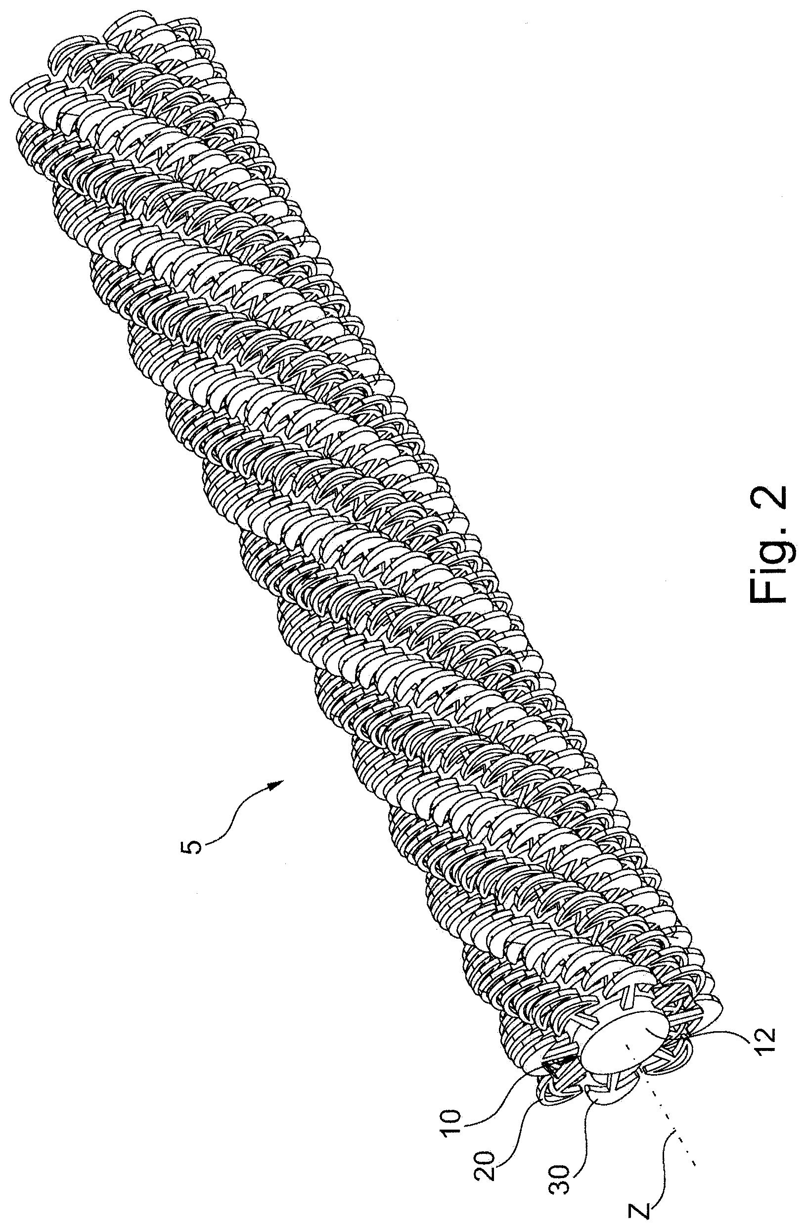
[0064] FIG. 2 shows the applicator part of an example of an applicator produced in accordance with the invention, on its own,
[0065] FIG. 3 shows an element used to produce the applicator part shown in FIG. 2, on its own,
[0066] FIG. 4 shows an example of a core on which the elements can be mounted, the core being shown before the mounting of the elements and twisting,
[0067] FIGS. 5, 7, 9, 11, 13, 15 and 19 are views similar to FIG. 3 of variant embodiments,
[0068] FIGS. 6, 8, 10, 12, 14, 16, 18 and 20 show the applicator parts produced with the elements in FIGS. 5, 7, 9, 11, 13, 15, 17 and 19, respectively, and
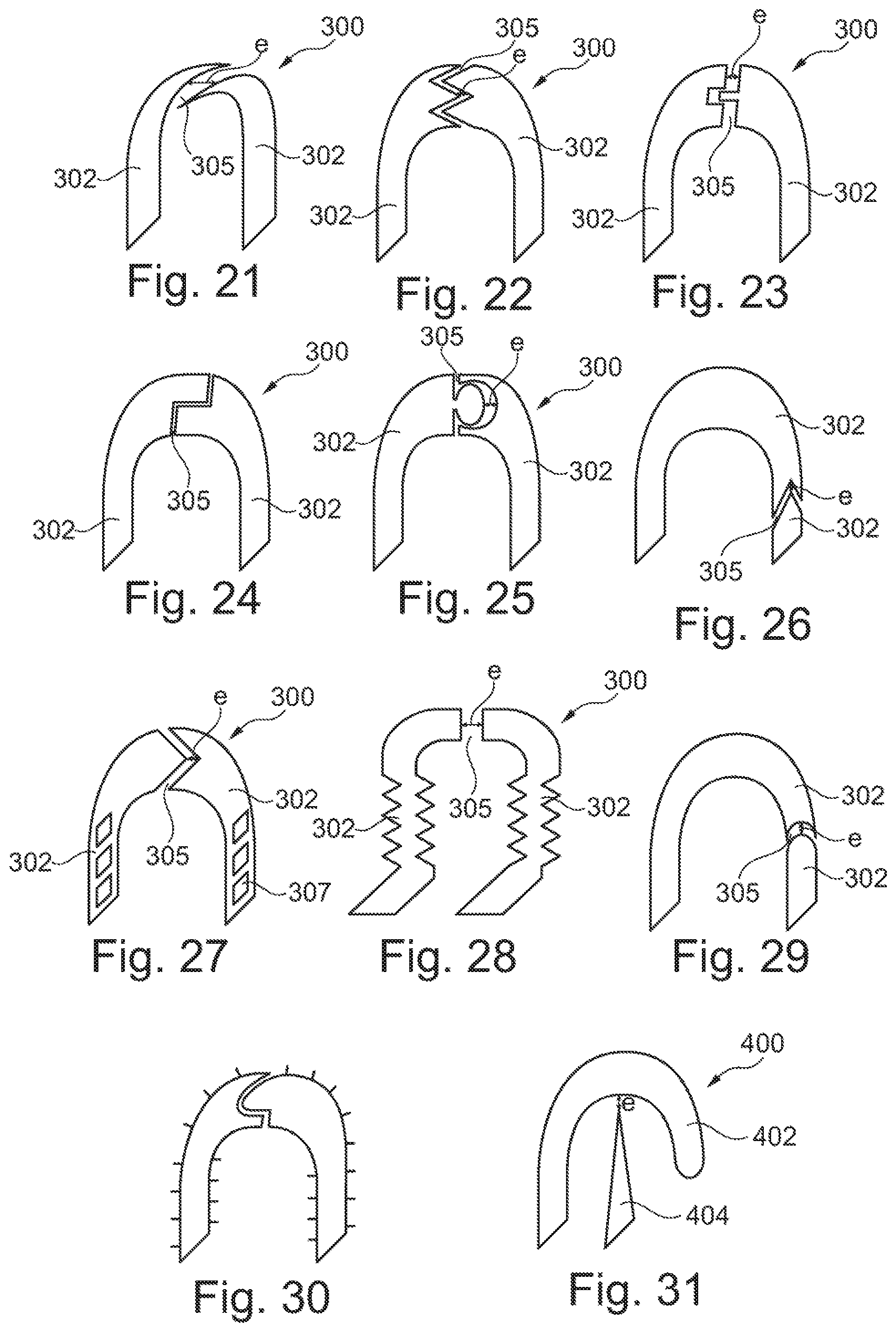
[0069] FIGS. 21 to 31 show variant embodiments.
[0070] The packaging and application device 1 shown schematically and partially in FIG. 1 has a container 2 containing the composition to be applied and an applicator 3 for applying this composition.
[0071] The container 2 has a body which is provided for example, as illustrated, with a threaded neck 4 to which the applicator 3 can be fastened when the device 1 is not being used.
[0072] A wiping member (not visible in the figure) is secured in the neck of the container, in the usual manner. It may be a flexible lip with a conical, wavy or other shape.
[0073] The applicator 3 has an applicator part 5 which is used for applying the composition, this applicator part 5 being mounted at one end of a stem 6, the other end of which is carried by a gripping member 7 that also constitutes, in the example in question, a closure member for the container 2, being designed to be fastened to the neck 4.
[0074] The composition which is applied may be constituted by any cosmetic product intended for making up or for caring for the eyelashes and/or eyebrows. Preferably, it is mascara. The composition may notably include pigments, such as iron oxides, dispersed in an aqueous or anhydrous medium. The capacity of the container is preferably between 5 and 30 ml.
[0075] FIG. 2 shows an example of an applicator part 5 produced from individual elements 10, one of which has been shown on its own in FIG. 3.
[0076] The applicator part 5 is preferably produced in accordance with the teaching of the U.S. Pat. No. 8,899,241 B2. The elements 10 are thus mounted on a core 9 that holds them in a stacked manner and securely relative to one another. This core 9 is for example a twisted core, produced from a metal wire folded into the form of a hairpin, as illustrated in FIG. 4.
[0077] In a variant, the core may be constituted by two separate metal wires that are positioned in a substantially parallel manner like the arms of the hairpin illustrated in FIG. 4, onto which the elements 10 are threaded and which are then twisted.
[0078] The elements 10 have holes 11, which are shown schematically in FIG. 3, for the arms 9a and 9b of the core to pass through before the latter is twisted.
[0079] For the sake of clarity of the drawing, the core 9 has not been shown in FIG. 2, and the holes 11 passing through the central part 12 are only shown in FIG. 3.
[0080] In the example in question, the elements 10 are identical, but it would not constitute a departure from the scope of the present invention if elements 10 of different shapes were stacked on the core 9 within the applicator part 5.
[0081] As can be seen in FIG. 3, each element 10 has application members 20 and 30 which engage with the eyelashes or eyebrows while the applicator 3 is being used. In the example in question, the application members 20 are hollow and alternate in the circumferential direction with the application members 30 which are solid.
[0082] The application elements 20 and 30 have, in this example, the same exterior shape, but it would not constitute a departure from the scope of the present invention if the exterior shapes were different.
[0083] The central part 12 is in the form of a flattened disk, the holes 11 for the arms 9a, 9b of the core 9 to pass through being disposed symmetrically relative to an axis X of the element 10, which may be an axis of symmetry for the central part 12.
[0084] The surface of the central part 12, to which the application members are joined, may be in the shape of a cylinder of revolution about the axis X, but further shapes are possible.
[0085] In the example illustrated, the application members 20 and 30 each have a flattened shape in a plane which is coincident with the flattening plane of the central part 12, this plane being perpendicular to the axis X and to the longitudinal axis Z of the applicator part 5.
[0086] The hollow application members 20 alternate with the solid application members 30, there being four hollow application members 20 in the example in question, which are disposed at 90 degrees to one another.
[0087] The cavity 14 of each hollow application member 20 is formed by a strand of material 63 which describes a closed curve constituting an enlarged head 60, this loop being joined to the central part 12 by a leg 61.
[0088] In the example illustrated, the enlarged head 60 has the overall shape of a harpoon with, for the hollow application members 20, a top arch 65, which has a substantially parabolic shape that is convex toward the outside, and a bottom arch 66, which is concave toward the central part 12 and has less of a curvature than the top arch 65.
[0089] The cavity 14 has a radial dimension which is thus at its maximum on the elongation axis Y of the application member and which decreases toward the top of the elbow formed by the meeting point between the arches 65 and 66.
[0090] At this meeting point, the enlarged head 60 defines teeth 65 which are oriented in a direction away from the axis Y and toward the central part, this orientation helping to catch more of the eyelashes which are introduced into the applicator part 5.
[0091] In the example illustrated, the distance e between the enlarged heads 60 of two adjacent application members 20, 30 on the element 10 is relatively small and less than the distance between the legs 61 at their base. The enlarged heads 60 are thus relatively close together. This distance e may be between 0.1 and 0.3 mm, being large enough to allow an eyelash to pass into the space 69 between two legs 61 under the enlarged heads 60.
[0092] When the spacing e is sufficiently small, preferably less than or equal to 0.3 mm, better still less than or equal to 0.2 mm, even better still less than or equal to 0.1 mm, a cavity, which is almost closed, where the composition can collect, is formed in the space 69 between the application members 20 and 30. This almost closed cavity extends as far as the central part 12 in the example in question. A bridge of composition can form by surface tension between the enlarged heads 60.
[0093] The small gap e tends to retain a certain quantity of composition outside the application members 20 and 30, in the recess 68 formed between the convex surfaces defining the top of the heads 60. This can make it easier for the eyelashes to access the composition with which the applicator part 5 is loaded.
[0094] It is possible to have a height h and a width l of the application member 20 or 30 which satisfy the relationship 0.5 h.ltoreq.l.ltoreq.2 h.
[0095] The straight line joining the closest-together regions of the facing portions, that is to say where the gap e is smallest, is situated at a distance u from the central part 12 of greater than 0.5 mm.
[0096] As mentioned above, in order to produce the applicator part 2, the elements 10 are threaded onto the core 9 and then the latter is twisted, as per the teaching of the patent U.S. Pat. No. 8,899,241 B2. The number of elements 10 is for example between 2 and 100, better still between 5 and 15.
[0097] In order to manufacture the elements 10, they can be molded in a suitable mold such that demolding takes place along the axis X.
[0098] In such a case, the presence of the cavity 14 within the hollow application elements 20 does not hamper demolding in any way.
[0099] In general, any thermoplastic material can be used to mold the elements 10, regardless of the shape of the central part 12 and of the application members joined thereto. It is possible notably to use a polyolefin or a thermoplastic elastomer, for example of the SEBS type.
[0100] It is also possible to produce the element 10 from a non-thermoplastic material, for example a metal or ceramic material.
[0101] During the twisting of the core, the elements 10 can undergo rotation relative to one another, such that a progressive angular offset is created between the elements, along the core, this being able, if appropriate, to create helical furrows in the applicator part 5.
[0102] While the applicator is being used, the composition can collect in the cavities 14 and between the enlarged heads 60, by virtue of their proximity, notably in the recess 68 formed between the arches 65 of two adjacent enlarged heads 60. The composition present in these recesses 68 is easily accessible to the eyelashes, at a distance from the central part 12. Thus, the eyelashes do not have to penetrate deeply into the brush in order to be loaded with product.
[0103] A variant embodiment of the applicator part 5 and of the elements 10 with which the latter is produced will now be described with reference to FIGS. 5 and 6.
[0104] In the example in FIG. 5, the element 10 only comprises hollow application members 20, unlike the example in FIGS. 2 and 3, where there is an alternation of application members of different natures in the circumferential direction.
[0105] All of the application members 20 are identical and each have a toothed shape. The cavities 14 are delimited by a strand of material 80 which describes a succession of pointed arches, which are concave toward the outside, teeth being formed at the meeting point between two arches. More particularly, in the example illustrated, the strand of material 80 describes, starting from the central part 12, a first pointed arch 81, which is joined to a second arch 82, forming a first tooth 86, this second arch 82 itself being joined to a third arch 83, forming a tooth 84.
[0106] Each application member 20 has a shape that is symmetric with respect to its elongation axis Y.
[0107] At their meeting point, the two arches 83 form a tooth 85, which defines the vertex of the hollow application member 20 and is situated on the elongation axis Y.
[0108] Each application member 20 thus has the overall shape of a holly leaf. In this example, the cavity 14 extends over substantially the entire height of the application member 20, less the thickness taken up by the strand of material 80. The height m of the cavity, measured along the elongation axis Y, that is to say along a radius in the example in question, is thus greater than or equal to half the height h. There is for example the following relationship between l and h 0.5 h.ltoreq.l.ltoreq.2 h.
[0109] FIG. 5 shows that the gap e which exists between two adjacent application members, at the teeth 86, is relatively small and preferably less than or equal to 0.3 mm, and may notably be between 0.1 and 0.3 mm. The distance u, measured radially, between the central part 12 and the line joining the vertex of the teeth 86 of two adjacent application members 20 is greater than 0.5 mm, being for example around 0.6 mm in the example illustrated.
[0110] In the example illustrated, the application members 20 substantially meet at their base, where the strands of material 80 are joined to the central part 12. The fact that the teeth 86 of the adjacent application members are relatively close together makes it possible to form, between the first arches 81 of two adjacent application members, reserves of product in a relatively confined space 90 which only communicates with the outside through a relatively narrow opening 91, of width e. The space 90 constitutes an almost closed cavity.
[0111] The arches 82 which extend on either side of this narrow opening 91 define a product collection surface at a non-zero radial distance from the central part 12. The user thus has a reserve of product in a space 94, where the eyelashes can be introduced, while benefiting from teeth formed at the meeting point between the different arches in order to grip the eyelashes.
[0112] All of the concavities formed by the different arches form a corresponding number of indentations in which product can collect, thereby increasing the loading capacity of the applicator part 5.
[0113] A variant embodiment of the applicator part 5 will now be described with reference to FIGS. 7 and 8.
[0114] In this example, the element 10 only has hollow application members 20 that define a corresponding number of cavities 14.
[0115] Each application member 20 is formed by two lateral arches 100 that are joined at their distal end by a top arch 101, the lateral arches 100 and the top arch 101 being concave toward the outside. The arches 100 and 101 form teeth 102 at their meeting points. The application member 20 is formed by a strand of material 105.
[0116] The product can collect in the concavity of the top arch 101, the bottom of which is set back from the vertex of the teeth 102 along the elongation axis Y. Product can also collect in the cavity 14 formed by the strand of material 105. The facing lateral arches 100 of two adjacent application members 20 define a space 111 between one another, in which product can also collect. This space communicates with the outside through a narrow opening 112, this opening 112 leading out between the two teeth 102 of the two adjacent application members 20.
[0117] The fact that the opening 112 is narrow, with a width e of preferably less than or equal to 0.3 mm, improves the retention of product between the hollow application members 20.
[0118] The application members 20 of the example in FIG. 7 thus make it possible to collect product in the cavity 14, and also in the recess of the top arch 101.
[0119] The teeth 102 favor the catching of the eyelashes on account of their oblique orientation relative to the elongation axis Y. Finally, the relatively small spacing e between the adjacent application members 20 also helps the eyelashes to catch, when the latter are able to be introduced into the space 111.
[0120] In the example illustrated, the lateral arches 100 of two adjacent application members meet at their base. The number of application members 20 is equal to eight.
[0121] As illustrated in FIG. 8, the elements 10 can be angularly offset within the applicator part 5, about the longitudinal axis Z thereof, on account of the twisting of the core.
[0122] In the example in FIGS. 9 and 10, the element 10 comprises an alternation of application members 30a and 30b which follow one another in the circumferential direction around the central part 12.
[0123] The application members 30a and 30b each have the overall shape of a V, with two diverging arms 140 toward the outside for the element 30a and two diverging arms 150 for the element 30b. The opening angle k' of the Vs is for example between 15 and 60, better still between 30 and 45.degree..
[0124] The arms 140 are bent toward the outside at their distal end and have two end portions 141 that are oriented perpendicularly to the elongation axis Y, which is an axis of symmetry for the application member and is coincident with a radius.
[0125] The arms 150 are likewise bent at their distal end, but at a greater angle than the arms 140, such that the end portions 151 formed by the elbows each form an acute angle c with the corresponding portion 152 of the arm which is joined to the central part 12.
[0126] The arms 140 meet at their base. The same goes for the arms 150.
[0127] The application members 30a and 30b thus each form two reliefs that are able to improve the catching of the eyelashes during make-up application.
[0128] Catching is particularly pronounced with the application members 30b on account of the orientation of the end portions 151.
[0129] In the example illustrated, the gap e between the free end of one portion 151 and the adjacent arm 140 of the neighboring application member 30a is small and preferably less than 0.3 mm, better still less than 0.2 mm, or even less than 0.1 mm, such that two application members 30a and 30b form, between one another, an almost closed cavity 156 that is able to collect a certain amount of composition.
[0130] The portions 141 and 151 can also define, between one another, a space that leads to the outside and contains composition, the latter being able to be retained between said portions on account of its viscosity. This collection of composition at a relatively large radial distance from the central part makes it easier for the eyelashes to access the composition.
[0131] As in the above-described examples, the elements 10 are angularly offset on the applicator part, on account of the twisting of the core, as illustrated in FIG. 10.
[0132] In the example in FIGS. 11 and 12, each element 10 of the applicator part 5 has a succession of identical application members 160, for example 14 thereof.
[0133] Each application member 160 has a leg 161 which extends along the elongation axis Y, and has four successive elbows 162 to 165, each at a right angle in the example in question.
[0134] The elbow 162 is directed in the clockwise direction, the elbow 163 toward the outside, the elbow 164 in the counterclockwise direction, and the elbow 165 toward the outside.
[0135] The elbows 163 and 164 form a groove 167 in the shape of a slot, the bottom of which is defined by a segment 168 of the application member.
[0136] The distal portion of the application member is defined by a segment 169 which is parallel to the segment 168 and perpendicular to the segment 170, which forms the elbow 162 with the leg 161.
[0137] The segment 169 is offset toward the segment 168 with respect to the leg 161.
[0138] The gap e between the elbows 162 and 163 of two consecutive application members on the element 10 is relatively small, and is much less than the distance between the legs of these application members and their base, notably preferably less than 0.3 mm, better still less than 0.2 mm, even better still less than 0.1 mm. The legs 161 thus each form, with the segment 168 which is directed from one of the application members toward the other, an almost closed cavity 166 in which the composition can collect.
[0139] The groove 167 makes it possible to form a reserve of composition radially away from the central part, thereby allowing the eyelashes to be loaded without the latter having to be dipped deeply into the applicator part.
[0140] The segment 172 which defines, with the distal segment 169, the elbow 164 also makes it possible to retain the composition on a surface radially away from the central part 12.
[0141] Moreover, the notch formed by the succession of elbows 162 to 164 forms a kind of hook that is able to improve the catching of the eyelashes on the applicator part 5.
[0142] The distal segments 169 make it possible to benefit from a surface having a high capacity for separating the eyelashes, since they make it easier to introduce the eyelashes between the application members.
[0143] Various modifications can be made to this example, notably with regard to the shape of the abovementioned groove, which may be V-shaped in one variant, in which case the number of elbows is reduced to three. In other variants, the number of elbows is higher.
[0144] In the variant embodiment in FIGS. 13 and 14, each application member 220 has a central arm 221 provided at its end with an enlarged head 222, and two lateral arms 223 that are disposed on each side of the central arm 221 and diverge toward the outside. The lateral arms 223 are formed by simple spikes. The arms 221 and 223 meet at their base.
[0145] The angle g of divergence between the axes of the lateral arms 223 is for example between 15 and 60.degree., better still between 30 and 45.degree..
[0146] This angle g and the length of the lateral arms 223 can be chosen such that their ends am sufficiently close together for them to be considered to form, with the central part 12, an almost closed cavity 225, the gap e between said ends preferably being less than or equal to 0.3 mm, or even 0.2 mm or 0.1 mm.
[0147] When they are close together, the adjacent lateral arms 223 of two consecutive application members 220 of an element 10 can help to retain a certain amount of composition at the end of the arms 223, at a radial distance from the central part 12.
[0148] The gap e between two adjacent lateral arms 223 protruding from two consecutive application members 220 is less than 0.3 mm, better still less than 0.2 mm, even better still less than 0.1 mm.
[0149] For example, there are the following relationships between the total length of the central arm, measured at the vertex of the head 222, and the height of the lateral arms, measured along the elongation axis Y: j>1.4 k, better still j>1.5 k, and preferably 1.4 k<j<3k.
[0150] The presence of the head 222 creates a discontinuity 224 at its base, which is able to improve the catching of the eyelashes by the applicator part.
[0151] Between the central arm and each lateral arm there is also a V-shaped groove that is open toward the outside, into which an eyelash can be introduced, which can help to take hold of the eyelash in order to spread the composition on its surface.
[0152] The elements 10 may be angularly offset along the applicator part 5, on account of the twisting of the core 9, as illustrated in FIG. 14.
[0153] The variant embodiment in FIGS. 15 and 16 has an alternation of application members 230 and 240 in the circumferential direction.
[0154] The application members 230 are in the shape of an outwardly facing arrow, while the application members 240 are in the shape of an inwardly facing arrow.
[0155] Each application member 230 thus has a leg 231 by which it is joined to the central part 12 and a head 232 with a shape that tapers toward the outside, forming, at its connection to the leg, discontinuities 232 which can be oriented substantially perpendicularly to the elongation axis Y of the application member 230.
[0156] The flat part of the head 232 is in this example parallel to the flattening plane of the central part 12.
[0157] The discontinuities 233 are for example situated more than half-way along the length of the application member starting from the central part 12.
[0158] The application members 240 have a radial arm 241 which is joined to an enlarged base 243 in the form of an arrowhead directed toward the central part 12.
[0159] Discontinuities 244 are formed at the meeting point of the arm 241 and the base 243, these discontinuities 244 being oriented perpendicularly to the axis Y.
[0160] The application members 230 make it possible to grip the eyelashes by virtue of the presence of the discontinuities 233 formed by the head 232. The tapered shape of the application members 230 ensures good penetration of the eyelashes therebetween.
[0161] Each head 232 and the adjacent radial arm 241 form a sort of guide against which an eyelash can press when it is introduced into the applicator part 5, which can guide them until they cross the corresponding discontinuity 233, the gap between the head 232 and the radial arm 241 being preferably sufficient to allow the passage of an eyelash.
[0162] The discontinuities 244 allow the collection of composition at a distance from the central part 12, in a more easily accessible zone for the eyelashes than the surface of the central part 12.
[0163] The gap e between the base 243 of an application member 240 and the leg 231 of an adjacent application member 230 is sufficiently small, preferably less than or equal to 0.3 mm, in order to create an almost closed cavity 250 in the space extending between the central part 12 and the edge of the discontinuity 244 along the leg 231 and the base 243.
[0164] Such a cavity 250 makes it possible to collect composition above the surface of the central part 12. The distance between the base of the leg 231 and the origin of the base 243 at the central part 12 may be greater than the spacing e, such that the cavity 250 narrows away from the central part 12.
[0165] The difference between the height t at which the discontinuities 233 are situated with respect to the central part 12, measured along the elongation axis Y of the application member 230 in question, and the height u at which the discontinuities 244 are situated, is for example between 0 and 5 mm, better still between 0.5 and 2.5 mm, being for example around 1 mm.
[0166] The elements 10 may be angularly offset along the applicator part, on account of the twisting of the core 9, as illustrated in FIG. 16.
[0167] A variant embodiment in which the application members 180 each have the overall shape of a V, with two arms 181 diverging toward the outside, having bases that meet, and being provided at the end with enlarged heads 182 in the form of disks, will now be described with reference to FIGS. 17 and 18.
[0168] The angle d of divergence between the axes of the arms 181 is for example between 15 and 60.degree., better still between 30 and 45.degree..
[0169] Each head 182 forms, with the arm 181 to which it is joined, a discontinuity 183 which makes it possible to improve the catching of the eyelashes with the applicator part 5.
[0170] The close-together heads 182 of two consecutive application members 180 can, when the gap e between them is sufficiently small, preferably less than or equal to 0.3 mm, better still less than or equal to 0.2 mm, even better still less than or equal to 0.1 mm, form an almost closed cavity 187, which is delimited on the inner side by the central part 12, on the sides by the arms 181, and on the outer side by the heads 182.
[0171] The heads 182 can receive a certain load of composition on their surface that faces towards the outside, thereby increasing the quantity of composition available on the outer surface of the applicator part 5. In particular, the composition can collect in the recess 188 formed between two heads 182 of consecutive application members, the latter being sufficiently close together for a bridge of composition to form by capillary action.
[0172] The elements 10 can be angularly offset along the applicator part, on account of the twisting of the core 9, as illustrated in FIG. 18.
[0173] The exemplary embodiment shown in FIGS. 19 and 20 has application members 200 that are each formed by three arms, namely a central arm 201, which extends along the elongation axis Y of the application member 200, is longest and is formed by a simple spike, and two diverging lateral arms 202, that deviate from the central arm 201 away from the central part 12 and are each provided at their end with an enlarged head 203, for example in the form of a disk or ball.
[0174] The length j of the central arm 201 is greater than the height k of the lateral arms 202 measured at the vertex of the head 203. For example, j>1.4 k, better still j>1.5 k, and preferably 1.4 k<j<3 k.
[0175] The angle f of divergence between the axes of the arms 202 is for example between 15 and 60, better still between 30 and 45.degree..
[0176] The arms 201 and 202 meet, for example, at their base.
[0177] The gap e between each head 203 and the central arm 201 is sufficiently small to form an almost closed cavity 205 that is able to collect a certain amount of composition.
[0178] Moreover, the composition can collect on the top of the heads 203, on either side of the central arm 201, on account of the proximity between the heads 203 and the central arm 201. Thus, when an eyelash is introduced into the applicator part 5, it can press against the head 203 and be loaded with composition. It can also be introduced between the heads 203 of two adjacent application members 201 that are spaced further apart than the heads 203 are from the central arm. The presence of the arms 202 provided with heads makes it possible to improve the catching of the eyelashes by the applicator part 5, by virtue of the discontinuity formed at the base of the head where it is joined to the arm, which tends to retain the eyelash.
[0179] FIGS. 21 to 30 display application member 300 that comprises two portions 302 that cooperate to form an unclosed loop. At their junction, the two portions 302 cooperate without touching each other such as a gap 305 is formed between them. The two portions 302 are separated from a distance e as illustrated. As illustrated on FIGS. 21 to 30, the two portions 302 can have, at their junction, surface that has complementary forms. The complementary form can be a plane surface, as illustrated in FIGS. 21 and 28, complementary forms with undulations, as illustrated in FIGS. 22 and 30, convex and concave forms, as illustrated on FIG. 29, triangular complementary forms, as illustrated in FIGS. 26 and 27, rectangular complementary forms, as illustrated in FIGS. 23 and 24, clipping complementary forms as illustrated in FIG. 25.
[0180] In FIGS. 2l to 25, 27 to 28 and 30, the gap 305 is disposed at the distal end of the application member 300. As a variant illustrated in FIGS. 26 and 29, the gap 305 can be between the distant end of the application member 300 and the base of the application member 300 such that the portions 302 has different lengths.
[0181] The application member 300 can comprise reliefs on at least one of the two portions 302, as illustrated in FIG. 28, or protrusions 307, as illustrated in FIG. 27, or flocking, as illustrated in FIG. 30.
[0182] FIG. 31 displays an application member 400 comprising an unclosed loop 402 opened at one of its extremity and a tooth 404 extending below the unclosed loop 402. The extremity 406 of the tooth 404 and the unclosed loop 402 are separated from each other of a distance e. When e pressure is applied on the unclosed loop 402, the latter can contact the tooth 404 that prevent it from deforming.
[0183] Of course, the invention is not limited to the examples that have just been described.
[0184] For example, the number of application members may be different in each of the examples.
[0185] It is possible to stack on the core elements 10 which are not identical, being made for example of different materials, notably with different hardnesses, and/or having application members with different shapes.
[0186] The core can be given a curvature, such that the applicator part extends along a curved longitudinal axis.
* * * * *
D00000
D00001
D00002
D00003
D00004
D00005
D00006
D00007
D00008
XML
uspto.report is an independent third-party trademark research tool that is not affiliated, endorsed, or sponsored by the United States Patent and Trademark Office (USPTO) or any other governmental organization. The information provided by uspto.report is based on publicly available data at the time of writing and is intended for informational purposes only.
While we strive to provide accurate and up-to-date information, we do not guarantee the accuracy, completeness, reliability, or suitability of the information displayed on this site. The use of this site is at your own risk. Any reliance you place on such information is therefore strictly at your own risk.
All official trademark data, including owner information, should be verified by visiting the official USPTO website at www.uspto.gov. This site is not intended to replace professional legal advice and should not be used as a substitute for consulting with a legal professional who is knowledgeable about trademark law.