Plug Connector
MENG; WEI ; et al.
U.S. patent application number 16/904817 was filed with the patent office on 2020-12-24 for plug connector. The applicant listed for this patent is FOXCONN INTERCONNECT TECHNOLOGY LIMITED, FOXCONN (KUNSHAN) COMPUTER CONNECTOR CO., LTD.. Invention is credited to JUN CHEN, YANG-TSUN HSU, WEI MENG, ZHENG-RONG ZHU.
| Application Number | 20200403338 16/904817 |
| Document ID | / |
| Family ID | 1000004928521 |
| Filed Date | 2020-12-24 |


| United States Patent Application | 20200403338 |
| Kind Code | A1 |
| MENG; WEI ; et al. | December 24, 2020 |
PLUG CONNECTOR
Abstract
A plug connector used to mate with the socket connector includes: a housing; a printed circuit board received in the housing, the circuit print board having plural soldering points; and a cable electrically connected to the soldering points of the printed circuit board, wherein the soldering points are provided with glue blocks to protect a connection between the printed circuit board and the cable.
| Inventors: | MENG; WEI; (Kunshan, CN) ; ZHU; ZHENG-RONG; (Kunshan, CN) ; CHEN; JUN; (Kunshan, CN) ; HSU; YANG-TSUN; (New Taipei, TW) | ||||||||||
| Applicant: |
|
||||||||||
|---|---|---|---|---|---|---|---|---|---|---|---|
| Family ID: | 1000004928521 | ||||||||||
| Appl. No.: | 16/904817 | ||||||||||
| Filed: | June 18, 2020 |
| Current U.S. Class: | 1/1 |
| Current CPC Class: | H01R 13/6275 20130101; H01R 43/205 20130101; H01R 13/506 20130101; H01R 12/72 20130101; H01R 43/0256 20130101 |
| International Class: | H01R 12/72 20060101 H01R012/72; H01R 43/02 20060101 H01R043/02; H01R 43/20 20060101 H01R043/20; H01R 13/506 20060101 H01R013/506; H01R 13/627 20060101 H01R013/627 |
Foreign Application Data
| Date | Code | Application Number |
|---|---|---|
| Jun 18, 2019 | CN | 201910526699.8 |
Claims
1. A plug connector used to mate with a socket connector comprising: a housing; a printed circuit board received in the housing, the circuit print board having a plurality of soldering points; and a cable electrically connected to the soldering points of the printed circuit board, wherein the soldering points are provided with glue blocks to protect a connection between the printed circuit board and the cable.
2. The plug connector as claimed in claim 1, wherein the housing includes a first housing and a second housing mating with the first housing.
3. The plug connector as claimed in claim 2, wherein the first housing includes a lower surface provided with a through hole, and the cable extends out of the first housing through the through hole.
4. The plug connector as claimed in claim 2, wherein the second housing includes a front end provided with an opening, and the printed circuit board extends out of the second housing through the opening.
5. The plug connector as claimed in claim 2, wherein the first housing includes blocks on both sides of the first housing, the second housing includes recessed holes on both sides of the second housing, and the blocks cooperate with the recessed holes to fix the first housing and the second housing.
6. The plug connector as claimed in claim 1, wherein the plug connector includes a step on the second housing and a locking spring member fixed on the step.
7. The plug connector as claimed in claim 6, wherein the locking spring member is provided with a convex hull for fixing.
8. A method of assembling a plug connector, comprising the steps of: providing a printed circuit board and soldering a cable to plural soldering points of the printed circuit board; providing glue blocks on the soldering point to protect a junction between the printed circuit board and the cable; forming a first housing at the junction between the cable and the printed circuit board; providing a second housing with an opening and installing the printed circuit board into the second housing through the opening; and providing a block on the first housing and a recessed hole on the second housing and assembling the first housing and the second housing together through cooperation of the block and the recessed hole.
9. The method as claimed in claim 8, further comprising forming a step on the second housing and a locking spring member fixed on the step.
10. The method as claimed in claim 9, wherein the locking spring member is provided with a convex hull for fixing.
11. An electrical connector comprising: a printed circuit board defining two opposite surfaces; a plurality of circuit pads formed upon a front region and a rear region of the printed circuit board on each surface; a pair of cables mechanically and electrically connected to the circuit pads on the rear region of said opposite surfaces, respectively; and an insulative rear housing over-molded upon front sections of the pair of cables and the rear region of the printed circuit board, wherein the printed circuit board extends in a front-to-back direction with thereof the rear region ds2embedded within the rear housing in a vertical direction perpendicular to the front-to-back direction; wherein the front sections of said pair of cables extend in the vertical direction while being embedded within the rear housing in the front-to-back direction.
12. The electrical connector as claimed in claim 11, further including an insulative front housing attached to the rear housing, wherein the front housing forms a hole extending therethrough in the front-to-back direction to have the front region of the printed circuit board extend therethrough to be exposed upon a front side of the front housing.
13. The electrical connector as claimed in claim 12, wherein the front housing forms a cavity in a rear side thereof to receive the rear housing therein.
14. The electrical connector as claimed in claim 12, wherein the front housing forms a U-shaped baffle plate below the front region of the printed circuit board.
15. The electrical connector as claimed in claim 14, wherein the front housing is equipped with a deflectable locking member above the front region of the printed circuit board opposite to the baffle plate.
16. The electrical connector as claimed in claim 12, wherein said front housing defines a T-configuration in a side view along a transverse direction perpendicular to both the front-to-back direction and the vertical direction.
17. The electrical connector as claimed in claim 12, wherein the front housing forms a hole to receive a protrusion of the rear housing for retention therebetween.
18. The electrical connector as claimed in claim 11, wherein connection between the cable and the circuit pads is equipped with glue block for protection.
19. The electrical connector as claimed in claim 11, wherein an outer cable of said pair of cables is sandwiched between a rear edge of the printed circuit board and the rear housing in the front-to-back direction.
Description
BACKGROUND OF THE DISCLOSURE
1. Field of the Disclosure
[0001] The present disclosure relates to a plug connector, in particular to a plug connector for easy assembly.
2. Description of Related Arts
[0002] China patent application publication No. 106785613A discloses a high-speed connector assembly which includes a board connector, and an wire end connector, the wire end connector includes an assembled housing, an inner mold filled in the housing, a printed circuit board covered with the inner mold and a cable soldered on the printed circuit board.
[0003] Since the wire end connector needs to be provided with injection holes, low-pressure injection of the inner film is into the assembled housing through the injection holes to cover all the welding points between the connecting cable and the printed circuit board. This design not only increases the manufacturing process, but also increases manufacturing costs.
[0004] Therefore, an improved plug connector is desired.
SUMMARY OF THE DISCLOSURE
[0005] Accordingly, an object of the present disclosure is to provide a plug connector for easy assembly.
[0006] To achieve the above object, a plug connector used to mate with a socket connector comprises: a housing; a printed circuit board received in the housing, the circuit print board having plural soldering points; and a cable electrically connected to the soldering points of the printed circuit board, wherein the soldering points are provided with glue blocks to protect a connection between the printed circuit board and the cable.
[0007] Other objects, advantages and novel features of the disclosure will become more apparent from the following detailed description when taken in conjunction with the accompanying drawings.
BRIEF DESCRIPTION OF THE DRAWINGS
[0008] FIG. 1 is a perspective view of a plug connector according to the present invention;
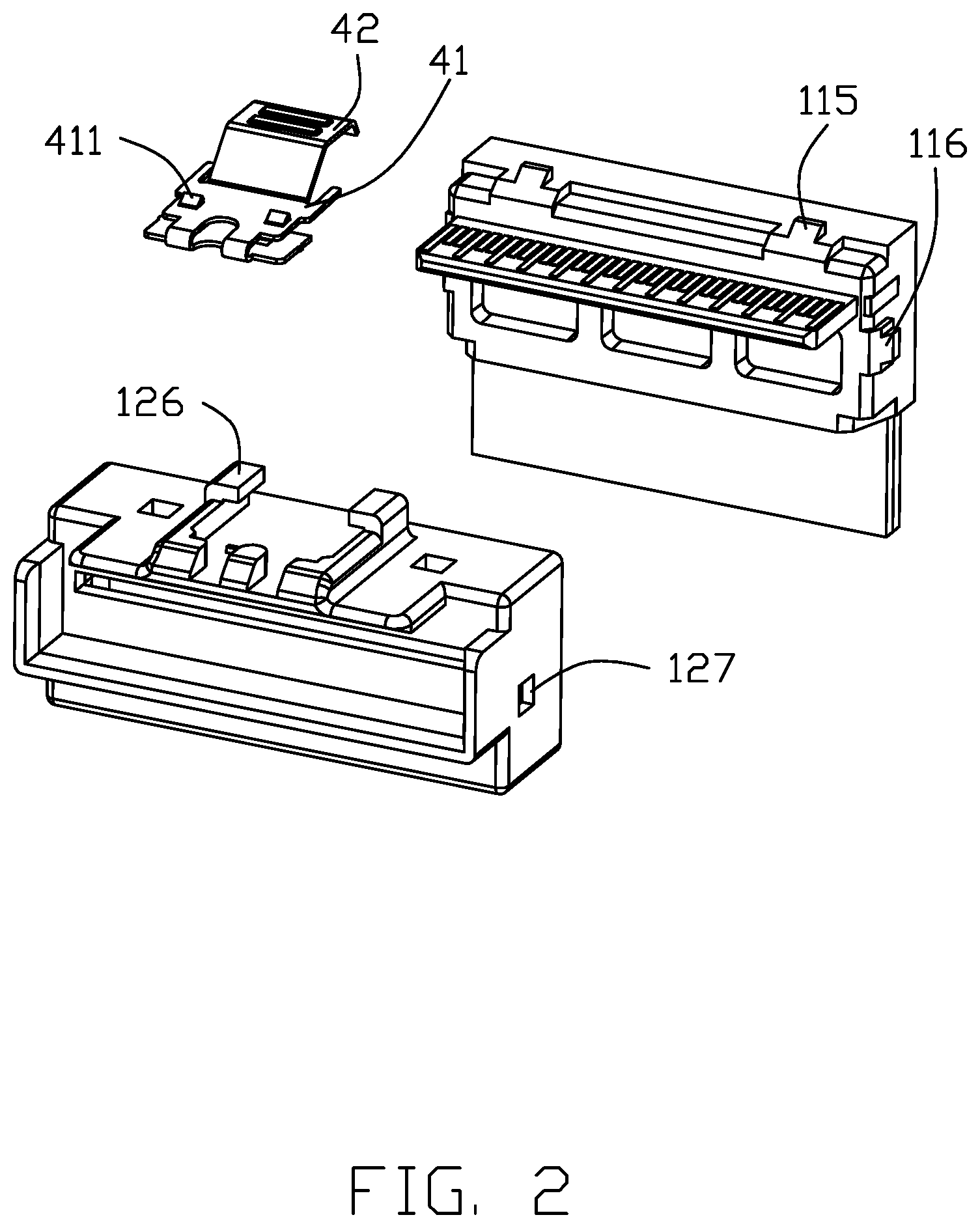
[0009] FIG. 2 is an exploded view of the plug connector as shown in FIG. 1;
[0010] FIG. 3 is another exploded view of the plug connector as shown in FIG. 2;
[0011] FIG. 4 is a further exploded view of the plug connector as shown in FIG. 2; and
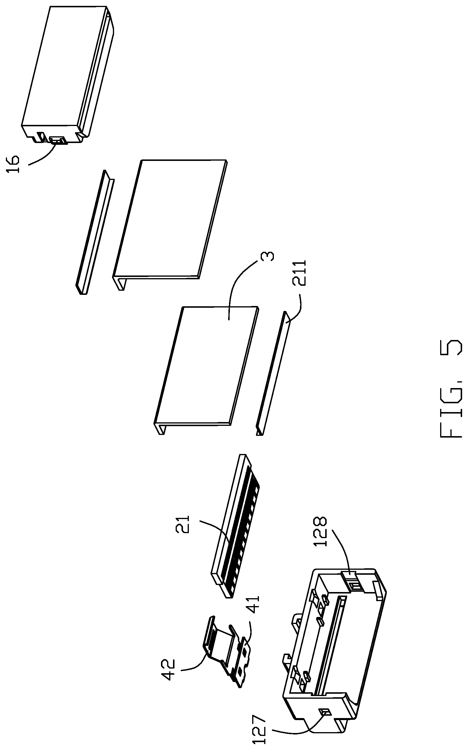
[0012] FIG. 5 is another further exploded view of the plug connector as shown in FIG. 4.
DETAILED DESCRIPTION OF THE PREFERRED EMBODIMENT
[0013] Reference will now be made in detail to the embodiments of the present disclosure.
[0014] Referring to FIGS. 1-5, a plug connector 100 used to mate with the socket connector includes a housing 1, a printed circuit board 2 received in the housing 1, a cable 3 electrically connected with the printed circuit board 2 and a locking spring member 4.
[0015] The housing 1 is an assembled housing and includes a first housing 11 and a second housing 12. The first housing 11 is formed at the connection between the printed circuit board 2 and the cable 3. The first housing 11 includes a first upper surface 111, a first left side 112 on the left side of the first upper surface 111, a first right side 113 on the right side of the first upper surface 111 and a lower surface 114 opposite to the first upper surface 111. The first upper surface 111 is provided with ribs 115 on both sides thereof. Both the first left side 112 and the first right side 113 are provided with a block 116 in a "convex" shape. The lower surface 114 is provided with a through hole 117 through which the cable 3 extends out of the first housing 11. The second housing 12 includes a second upper surface 121, a second left side 122 on the left side of the second upper surface 121, a second right side 123 on the right side of the second upper surface 121 and a front end 124. The second upper surface 121 includes a groove 125 that cooperates with the ribs 115 and a step 126 for holding the locking spring member. Both the inner side of the second left side surface 122 and the second right side surface 123 are provided with a recessed hole 127 for holding the block 116 and a sliding groove 128 for guiding the block 116 to cooperate with the recessed hole 127. The front end 124 is provided with an opening 129 through which the printed circuit board 3 extends out of the second housing 121. The second housing 12 further includes a baffle 130 extending forward from both sides and a lower side of the front end 124, and the baffle plate 130 is U-shaped.
[0016] The connection direction of the printed circuit board 2 is perpendicular to the connection direction of the cable 3. The printed circuit board 2 includes, at the rear side, a plurality of soldering points or circuit pads 21 connected to the cable 3, and the soldering points 21 are provided with glue blocks to protect the connection between the printed circuit board 2 and the cable 3, and the cost can be saved. The printed circuit board 2 further includes, at the front side, a plurality of circuit pads (not labeled) for mating with the corresponding resilient contacts of the complementary connector.
[0017] The front end of the cable 3 is connected to the printed circuit board 2, and the rear end extends downward from the second housing 12.
[0018] The locking spring member 4 includes an elastic piece 41 fixed to the step 126 and a pressing piece 42 provided at the rear end of the elastic piece 41. The upper surface of the elastic piece 41 is provided with a locking protrusion 411 for cooperating with the locking hole of the socket connector. The elastic piece 41 can drive the locking protrusion 411 to swing elastically up and down. When the user manually presses the pressing piece 42, the elastic piece 41 can be caused to swing downward to unlock the socket connector.
[0019] The production method of the plug connector 100 in the above embodiment includes the following steps: provide a printed circuit board 2 and a cable 3 perpendicular to the connection direction of the printed circuit board solder the cable 3 to the soldering points 21 of the printed circuit board 2, and protect the connection between the printed circuit board 2 and the cable 3 by providing glue blocks 211 on the soldering points 21; provide a first housing 11 is formed at the connection between the cable 2 and the printed circuit board 3, and a through hole 117 is provided on the lower surface 114 of the first housing 11 to pass the cable 3 through the through hole 117 and extend out of the first housing 11 provide a second housing 12 with an opening 129, install the printed circuit board 2 into the second housing 12 through the opening 129; ribs 115 is provided on the upper surface of the first housing 11, and a groove 125 corresponding to the ribs 115 is provided on the upper surface of the second housing 12; blocks 116 are provided on both sides of the first housing 11, and corresponding holes 127 and slide grooves 128 are provided on both sides of the second housing 12 the ribs 115 cooperates with the hole 127 through the sliding groove 128 to assemble the first housing 11 and the second housing 12 together.
* * * * *
D00000
D00001
D00002
D00003
D00004
D00005
XML
uspto.report is an independent third-party trademark research tool that is not affiliated, endorsed, or sponsored by the United States Patent and Trademark Office (USPTO) or any other governmental organization. The information provided by uspto.report is based on publicly available data at the time of writing and is intended for informational purposes only.
While we strive to provide accurate and up-to-date information, we do not guarantee the accuracy, completeness, reliability, or suitability of the information displayed on this site. The use of this site is at your own risk. Any reliance you place on such information is therefore strictly at your own risk.
All official trademark data, including owner information, should be verified by visiting the official USPTO website at www.uspto.gov. This site is not intended to replace professional legal advice and should not be used as a substitute for consulting with a legal professional who is knowledgeable about trademark law.