Control System For Charging Of Non/partially Insulated Superconducting Magnets And Related Techniques
BRUNNER; Daniel ; et al.
U.S. patent application number 16/444784 was filed with the patent office on 2020-12-24 for control system for charging of non/partially insulated superconducting magnets and related techniques. The applicant listed for this patent is Massachusetts Institute of Technology. Invention is credited to Daniel BRUNNER, Robert MUMGAARD.
| Application Number | 20200402692 16/444784 |
| Document ID | / |
| Family ID | 1000004990453 |
| Filed Date | 2020-12-24 |


| United States Patent Application | 20200402692 |
| Kind Code | A1 |
| BRUNNER; Daniel ; et al. | December 24, 2020 |
CONTROL SYSTEM FOR CHARGING OF NON/PARTIALLY INSULATED SUPERCONDUCTING MAGNETS AND RELATED TECHNIQUES
Abstract
A system comprises a superconducting magnet comprising a coil of superconducting material. The coil includes two electrical terminals. The windings of the coil are separated by a metallic conductor. A control circuit is coupled to the two terminals to drive a current through the coil to charge the superconducting magnet and configured to provide a current through the coil that is sufficiently small to avoid a quenching effect of the superconducting magnet but also large enough to charge the magnet within a predetermined time period. A cooling structure is thermally coupled to the coil to remove heat caused by charging the superconducting magnet with the current to allow for the current to be sufficiently large to charge the magnet within the predetermined time period without causing the quenching effect.
| Inventors: | BRUNNER; Daniel; (Cambridge, MA) ; MUMGAARD; Robert; (Boston, MA) | ||||||||||
| Applicant: |
|
||||||||||
|---|---|---|---|---|---|---|---|---|---|---|---|
| Family ID: | 1000004990453 | ||||||||||
| Appl. No.: | 16/444784 | ||||||||||
| Filed: | June 18, 2019 |
| Current U.S. Class: | 1/1 |
| Current CPC Class: | H01F 6/04 20130101; H01F 6/06 20130101; H01F 6/02 20130101 |
| International Class: | H01F 6/06 20060101 H01F006/06; H01F 6/02 20060101 H01F006/02; H01F 6/04 20060101 H01F006/04 |
Claims
1. A system comprising: a superconducting magnet comprising a coil of superconducting material, the coil comprising two electrical terminals, wherein the windings of the coil are separated by a metallic conductor; a control circuit coupled to the two terminals to drive a current through the coil to charge the superconducting magnet, and configured to provide a current through the coil that is sufficiently small to avoid a quenching effect of the superconducting magnet but also large enough to charge the magnet within a predetermined time period; a cooling structure thermally coupled to the coil to remove heat caused by charging the superconducting magnet with the current to allow for the current to be sufficiently large to charge the magnet within the predetermined time period without causing the quenching effect.
2. The system of claim 1 wherein the cooling structure is configured to maintain a temperature of the coil at 4 deg K or higher.
3. The system of claim 1 wherein the control circuit further comprises one or more feedback loops.
4. The system of claim 3 wherein the one or more feedback loops feeds back a temperature of the coil.
5. The system of claim 3 wherein the one or more feedback loops feeds back a current through the coil.
6. The system of claim 3 wherein the one or more feedback loops feeds back a magnetic field of the coil.
7. The system of claim 1 wherein the control circuit comprises a model of the coil.
8. The system of claim 7 wherein the model comprises a temperature limit of the coil, a current limit of the coil, and a magnetic field limit of the coil.
9. The system of claim 8 wherein the temperature limit, the current limit, and the magnetic field limit define a region within which the coil acts as a superconductor.
10. A method of controlling a superconducting magnetic coil comprising: driving, by a variable current supply, a current through the superconducting magnetic coil; monitoring, by a control circuit, the current through the superconducting magnetic coil, a temperature of the superconducting magnetic coil, and a magnetic field about the superconducting magnetic coil; comparing, by the control circuit, the temperature, current, and magnetic field to model of the superconducting magnetic coil stored in the control circuit to determine a current operating point of the superconducting magnetic coil, wherein the model defines an operating range for the superconducting magnetic coil within which the coil acts as a superconductor; determining a maximum current that can be used to charge the coil based on the operating point of the superconducting magnetic coil and the operating range of the superconducting magnetic coil; and adjusting the current to match the maximum current to energize the superconducting magnetic coil.
11. The method of claim 10 further comprising controlling, by the control circuit, a cooling system to cool the superconducting magnetic coil while applying the maximum current so that the superconducting magnetic coil remains in the operating range.
12. The method of claim 11 wherein the cooling structure is configured to maintain a temperature of the coil at 4 deg K or higher.
13. The method of claim 10 wherein the control circuit further comprises one or more feedback loops.
14. The method of claim 13 wherein the one or more feedback loops feeds back a temperature of the coil.
15. The method of claim 13 wherein the one or more feedback loops feeds back a current through the coil.
16. The system of claim 13 wherein the one or more feedback loops feeds back a magnetic field of the coil.
17. The method of claim 10 wherein the model comprises a temperature limit of the coil, a current limit of the coil, and a magnetic field limit of the coil.
18. The method of claim 17 wherein the temperature limit, the current limit, and the magnetic field limit define a region within which the coil acts as a superconductor.
19. The method of claim 1 wherein windings of the superconducting magnetic coil are separated by a metallic conductor.
Description
FIELD
[0001] This disclosure relates to superconducting magnets and, more particularly, to superconducting magnets using partial- and no-insulation.
BACKGROUND
[0002] As is known in the art, superconducting magnets having partial- and/or no-insulation (PI/NI) between the superconducting turns are used because they can be designed to be passively safe during quenches. A quench is the transition from superconductor to normal conductor due to the current in the superconductor exceeding a threshold in the operating magnetic field, temperature, and/or current density. A quench can deposit a significant amount of the energy stored in the magnetic field as thermal energy in a small volume of the magnet, which may cause damage to some or all portions of the superconducting magnet. PI/NI magnets can avoid this by allowing the current to flow around the quench zone to adjacent superconducting turns and/or couples the quench electromagnetically to adjacent turns.
SUMMARY
[0003] In accordance with one aspect of the concepts described herein, it has been recognized that the reduction and/or entire elimination of insulation in a superconducting magnet means that voltages generated between the PI/NI superconducting layers (e.g., inductive voltages generated during charging and discharging) may cause a current to flow through any electrically conductive layers. This typically effectively places a resistance (R) in parallel with an inductance (L) of the superconducting magnet thereby effectively forming a parallel L-R circuit.
[0004] Such a situation can be problematic for at least two reasons. First, superconducting magnets are often charged with a current-controlled power source. In PI/NI magnets, the charging or discharging time may be on the order of the LJR timescale, which can be up to many hours for large-L, low-R PI/NI magnets. Because of this, PI/NI superconducting magnets are typically only used for DC magnets (i.e., ones that are turned on to a give field and held there for long periods of time). Second, the current flowing through the resistive portion of the magnet generates heat. This heat must be removed by a cooling system and the resultant temperature increase must be compatible with the superconducting operation (it remains under the critical surface).
[0005] To overcome the limitation of slow charging times, the coil terminals can effectively be overdriven, providing a much larger inductive voltage to increase the ramp rate of current in the superconductor. However, this also increases the current flowing through the resistive portion of the magnet. Thus, in accordance with the concepts, systems, circuits and techniques sought to be protected herein, described is a control system that ramps (and ideally, optimally ramps) or otherwise controls a current in a superconductor while also controlling the effects of the current flowing through a resistive element to ensure the magnet remains superconducting.
[0006] In an embodiment, a system comprises a superconducting magnet which itself comprises a coil of superconducting material. The coil includes two electrical terminals. Windings of the coil are separated by a metallic conductor. A control circuit is coupled to the two terminals to direct or otherwise drive a current through the coil to charge the superconducting magnet. Further, the control circuit is configured to provide a current through the coil that is sufficiently small to avoid a quenching effect of the superconducting magnet but also large enough to charge the magnet within a predetermined time period. A cooling structure is thermally coupled to the coil to remove heat caused by charging the superconducting magnet with the current to allow for the current to be sufficiently large to charge the magnet within the predetermined time period without causing the quenching effect.
[0007] One or more of the following features may be included either individually or in combination.
[0008] The cooling structure may be configured to maintain a temperature of the coil at 4 K or higher.
[0009] The control circuit may comprise one or more feedback loops.
[0010] The one or more feedback loops may feed back a temperature of the coil.
[0011] The one or more feedback loops may feedback a current through the coil.
[0012] The one or more feedback loops may feedback a magnetic field of the coil.
[0013] The control circuit may include a model of the coil.
[0014] The model may include a temperature limit of the coil, a current limit of the coil, and a magnetic field limit of the coil.
[0015] The temperature limit, the current limit, and the magnetic field limit may define a region within which the coil acts as a superconductor.
[0016] In another embodiment, a method of controlling a superconducting magnetic coil includes driving, by a variable current supply, a current through the superconducting magnetic coil; monitoring, by a control circuit, the current through the superconducting magnetic coil, a temperature of the superconducting magnetic coil, and a magnetic field about the superconducting magnetic coil; comparing, by the control circuit, the temperature, current, and magnetic field to a model of the superconducting magnetic coil stored in the control circuit to determine a current operating point of the superconducting magnetic coil; determining a maximum current that can be used to charge the coil based on the operating point of the superconducting magnetic coil and the operating range of the superconducting magnetic coil; and adjusting the current to match the maximum current to energize the superconducting magnetic coil. The model defines an operating range for the superconducting magnetic coil within which the coil acts as a superconductor
[0017] One or more of the following features may be included.
[0018] The control circuit may control a cooling system to cool the superconducting magnetic coil while applying the maximum current so that the superconducting magnetic coil remains in the operating range.
[0019] The cooling structure may be configured to maintain a temperature of the coil at 4 K or higher.
[0020] The control circuit may further comprise one or more feedback loops.
[0021] The one or more feedback loops may feedback a temperature of the coil.
[0022] The one or more feedback loops may feedback a current through the coil.
[0023] The one or more feedback loops may feedback a magnetic field of the coil.
[0024] The model may include a temperature limit of the coil, a current limit of the coil, and a magnetic field limit of the coil.
[0025] The temperature limit, the current limit, and the magnetic field limit may define a region within which the coil acts as a superconductor.
[0026] Windings of the superconducting magnetic coil may be separated by a metallic conductor.
BRIEF DESCRIPTION OF THE DRAWINGS
[0027] The foregoing features may be more fully understood from the following description of the drawings. The drawings aid in explaining and understanding the disclosed technology. Since it is often impractical or impossible to illustrate and describe every possible embodiment, the provided figures depict one or more exemplary embodiments. Accordingly, the figures are not intended to limit the scope of the invention. Like numbers in the figures denote like elements.
[0028] FIG. 1 is a block diagram of a magnetic coil and control circuit.
[0029] FIG. 2 is a three-dimensional graph of an operational model of a superconducting magnet.
[0030] FIG. 3 is a block diagram of an embodiment of a control circuit for a superconducting magnet.
[0031] FIG. 4 is a perspective view of a simplified tokamak fusion power system.
[0032] FIG. 4A is a block diagram of a portion of a magnetic coil in a fusion power system.
[0033] FIG. 5 is a perspective view of a spiral plate and superconducting tape for use in a superconducting magnet.
[0034] FIG. 6 is a block diagram of a computing device.
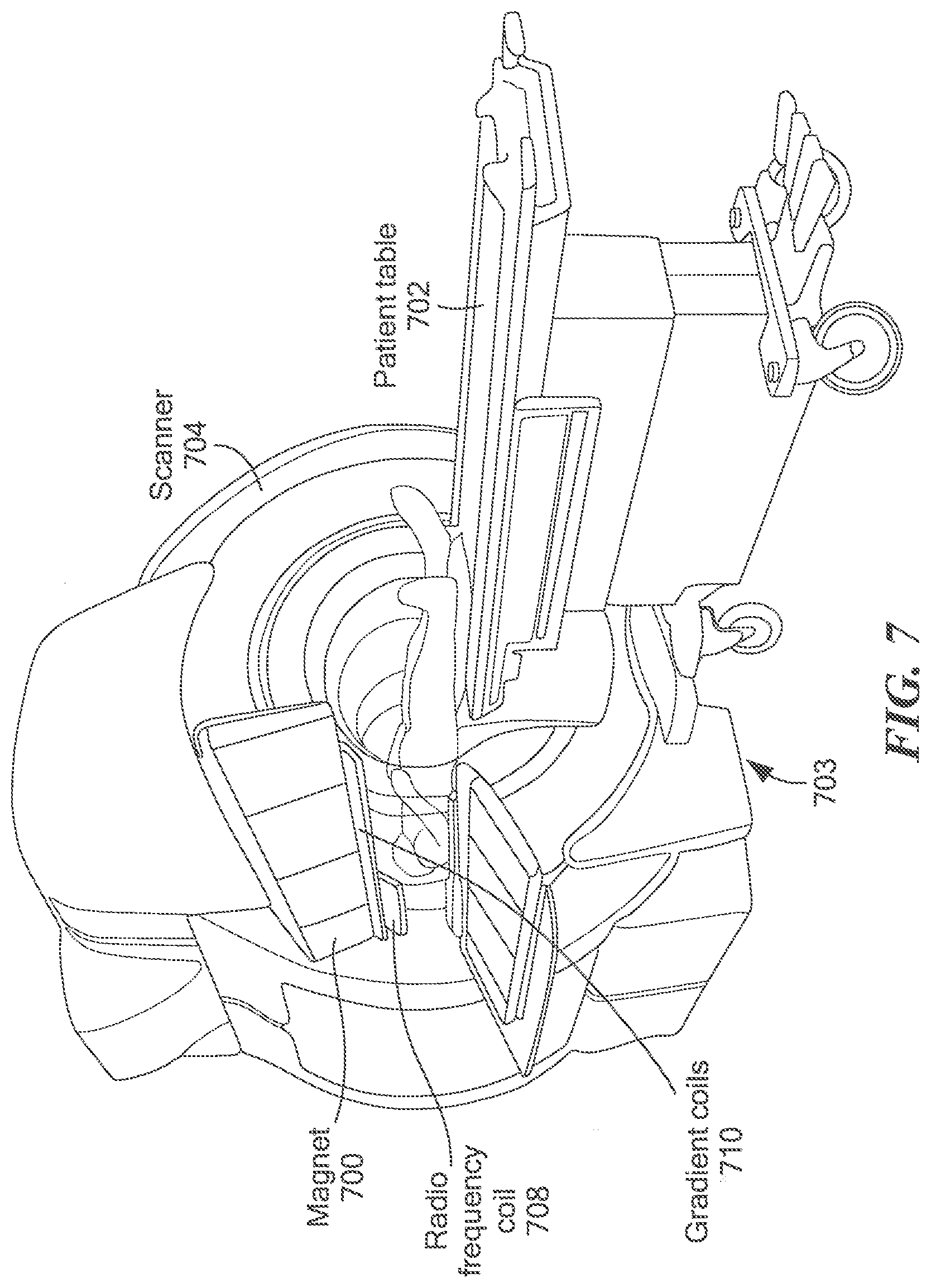
[0035] FIG. 7, an isometric partial cut-away view of an MRI system which includes a control circuit which may be the same as or similar to the control circuit of FIGS. 1 and 3.
DETAILED DESCRIPTION
[0036] This disclosure relates to control systems for superconducting magnets for use in a wide variety of applications. As will be discussed below, the superconducting magnets may comprise a coil of superconducting material through which current flows to generate a magnetic field.
[0037] Before proceeding with a description of illustrative control circuits for use with superconducting magnets, some introductory concepts are explained. It should be appreciated that while reference may be made herein to specific applications, such references are made solely to promote clarity in explaining the broad concepts described herein. It should be appreciated that the concepts, systems, circuits and techniques described herein find use in a wide variety of different applications.
[0038] For example, after reading the description provided herein, one of ordinary skill in the art will readily appreciate that the concepts, systems, circuits and techniques described herein are generally applicable for use in a wide range of applications (e.g. a wide range of industrial uses) which may make use of high-field magnets and that the described control concepts, control systems, control circuits and control techniques may facilitate commercialization of high-field magnets for use in a wide variety of different applications. Such applications include but are not limited to: applications in the medical and life sciences field (e.g. magnetic resonance imaging and spectroscopy); applications in the chemistry, biochemistry and biology fields (e.g. nuclear magnetic resonance (NMR), NMR spectroscopy, electron paramagnetic resonance (EPR), and Fourier-transform ion cyclotron resonance (FT-ICR)); applications in particle accelerators and detectors (e.g. for use in health care applications such as in instruments for radiotherapy); application in devices for generation and control of hot hydrogen plasmas; applications in the area of transportation; applications in the area of power generation and conversion; applications in heavy industry; applications in weapons and defense; applications in the area of high-energy particle physics; and applications in the area of fusion power plants (e.g. compact fusion power plants).
[0039] Thus, although reference is sometimes made herein to the use of high-field magnet assemblies including the subject control circuits in connection with a specific application (e.g. fusion or MRI) such references are not intended to be, and should not be construed as, limiting. Rather, it should be appreciated that control circuits and systems for high-field magnet assemblies provided in accordance with the concepts described herein find use in a wide variety of applications.
[0040] Referring now to FIG. 1, a system 100 for controlling magnetic coil 102 may include control circuit 101 to monitor magnetic coil 102, control (and ideally optimize) current ramping and cooling as well as reduce (and ideally minimize) the occurrence of quenching. Control circuit 101 may be coupled to a variable current or voltage source 104 that drives current through magnetic coil 102. Control circuit 101 may vary the current through magnetic coil 102 by controlling variable current or voltage supply 104.
[0041] A cooling system may be coupled to magnetic coil 102 to control the temperature of magnetic coil 102. In embodiments, the value may be a variable threshold based on a model of magnetic coil 102, which will be discussed below. The cooling system may minimally include a liquid cooling channel 106 coupled to magnetic coil 102. In other embodiments, a conducting cooling system may be used. In embodiments, liquid cooling channel 106 may be closely thermally coupled to magnetic coil 102 to maximize the cooling that cooling channel 106 can provide to the coil. For example, cooling channel 106 may be physically coupled to a thermal conductor (such as a copper strip or plate, not shown), which in turn is directly physically coupled to magnetic coil 102.
[0042] In embodiments, cooling channel 106 may be a pipe or tube that contains a cooling fluid. Pump 108 may pump the cooling fluid through cooling channel 106 so that it circulates through magnetic coil 102 and removes heat. Although not shown, the cooling system may also include a condenser, a compressor, a cooling vat, a cooling tower, etc.
[0043] In embodiments, magnetic coil 102 may be a so-called high temperature superconductor. In this case, the cooling system may be configured to maintain the temperature of magnetic coil 102 at 4 degrees Kelvin, 10 degrees Kelvin, or higher, or any temperature above the boiling point of liquid Helium.
[0044] Control circuit 101 may also be coupled to control the cooling system. For example, control circuit 101 may control pump 108, a condenser (not shown), a compressor (not shown) or other elements of the cooling system to provide cooling to magnetic coil 102. In general, control circuit 101 may be able to control the amount of cooling that the cooling system provides to magnetic coil 102 by operating pump 108 at different speeds, by adjusting valves, by turning a compressor or condenser on and off, etc.
[0045] Control circuit 101 may also monitor the state of magnetic coil 102. For example, control circuit 101 may be coupled to a magnetic field sensor 110 to monitor the strength of the magnetic field produced by magnetic coil 102. Although shown as a loop sensor, magnetic field sensor 110 may be a Hall effect sensor, a magnetoresistance element, or any type of magnetic field detection device.
[0046] Control circuit 101 may also be coupled to temperature sensor 112, which may be thermally coupled to magnetic coil 102 so that control circuit 101 can monitor the temperature of magnetic coil 102.
[0047] Additionally, because control circuit 101 controls current source 104, control circuit 101 may monitor the amount of current flowing through magnetic coil 102. In embodiments, system 100 may include a current or voltage sensor (e.g. coupled to magnetic coil 102 and/or current source 104) that can sense the amount of current flowing through magnetic coil 102. In this case, control circuit 101 may be coupled to the current or voltage sensor and may use the current or voltage sensor to monitor the current flowing through magnetic coil 102.
[0048] Control circuit 101 may be implemented as a custom logic circuit, a programmed FPGA, a general-purpose computer programmed with software, a special-purpose computer programmed with software, or any type of circuit, system, or computing device that can act as a control system to control cooling to and current through magnetic coil 102. In embodiments, control circuit 101 may include a memory 114 that can store data for use by control circuit 101. Memory 114 may be a non-volatile memory such as an EPROM, a volatile memory that is loaded with the data required by control circuit 101, or a hard-programmed memory such as a logic circuit that acts as a memory. In embodiments, memory 114 may contain data representing an operating model for magnetic coil 102.
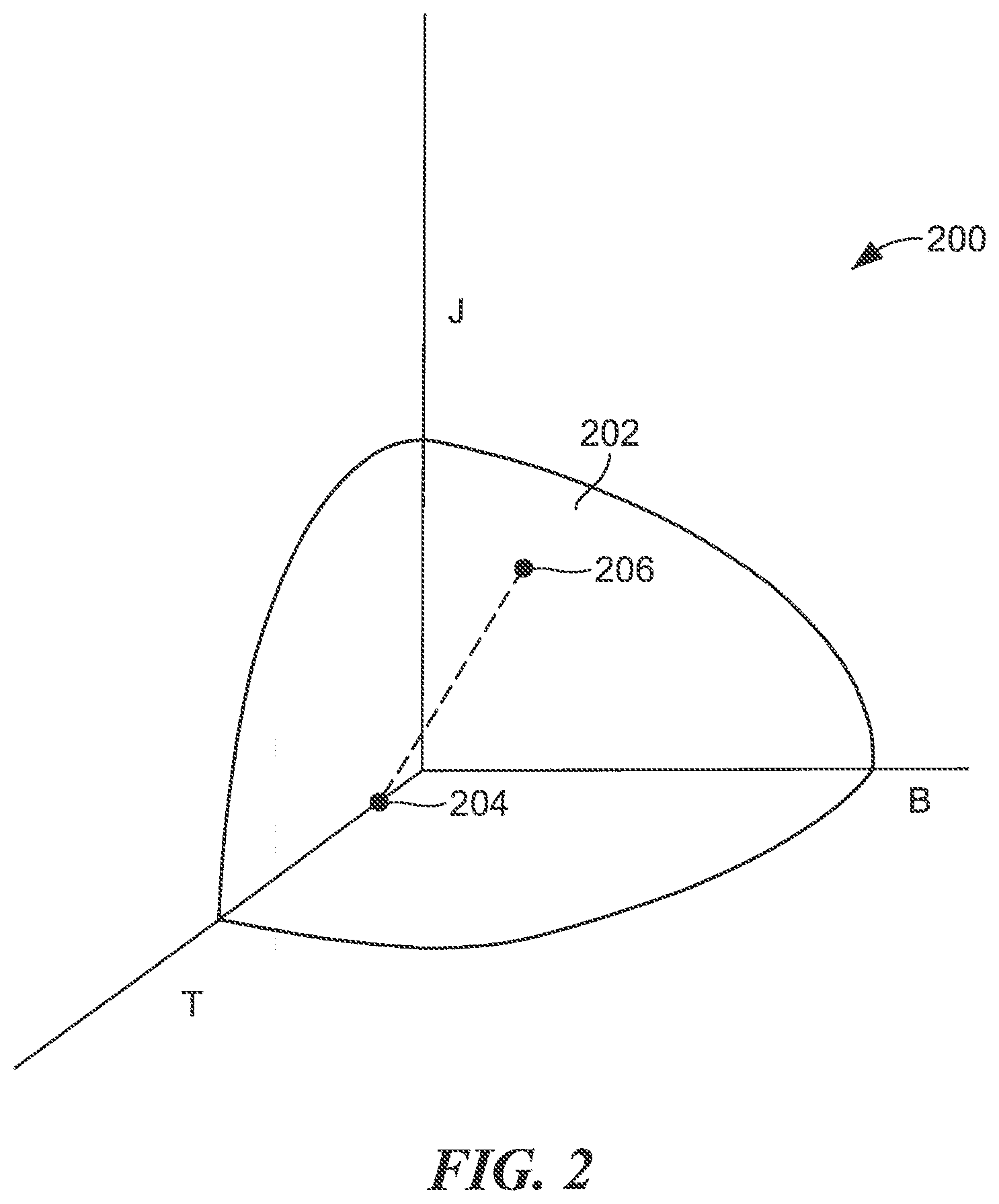
[0049] Referring now to FIG. 2, the three-dimensional graph represents an operating model 200 for magnetic coil 102 (and/or (and/or a superconducting tape). The J axis represents the current density flowing through a coil or a superconducting tape, the B axis represents the magnetic field to which a magnetic coil or superconducting tape (e.g. coil 102 or tape 508) is exposed to (produced by current flowing through the magnetic coil 102 as well as any magnets external to the magnetic coil 102), and the T axis represents the temperature of magnetic coil (e.g. coil 102) and/or superconducting tape.
[0050] Curve 202 represents the boundary of superconductivity of a magnetic coil (e.g. coil 102) and/or a superconducting tape. While the magnetic coil (or tape) is operating below curve 202, it may act as a superconductor. However, if the current density J, magnetic field B, and/or temperature T becomes too high and the operating point moves above curve 202, the magnetic coil (or tape) may lose its superconducting properties, in whole or in part, and begin to quench.
[0051] Using model 200, control circuit 101 may be able to provide the maximum rate change of current to magnetic coil 102 in order to energize magnetic coil 102 without allowing magnetic coil 102 to quench. For example, assume that point 204 represents the state of magnetic coil 102 at start-up, before any current is flowing through magnetic coil 102 (i.e. point 204 occurs at a finite value of temperature (T) and at zero current density (J) and zero magnetic field (B)). To energize magnetic coil 102, control circuit 101 may provide a terminal current such that the current density J in the superconductor is at or below point 206 without causing magnetic coil 102 to quench. Generally, as the current density J increases, the magnetic field B increases linearly. As the magnetic field B and temperature T change, control circuit 101 can change the amount of current flowing through magnetic coil 102 and/or the amount of cooling provided to magnetic coil 102 so that magnetic coil 102 remains in a superconducting state. Control circuit 101 may reduce (and ideally) minimize the time it takes to energize magnetic coil 102 by providing an increased current (and ideally a maximum or near maximum current) to magnetic coil 102 while keeping the operating point of magnetic coil 102 below surface 202.
[0052] In embodiments, data representing model 200 may be stored in memory 114. Model 200 may be represented as a formula, a series of formulas, a data table, a lookup table, or any other type of data that can be used to represent the superconducting operating of magnetic coil 102.
[0053] Referring now to FIG. 3, a block diagram illustrates a control system 300 for controlling a magnetic coil. Control system 300 may be the same as or similar to the control system described above in connection with FIG. 1.
[0054] Control system 300 may include a control circuit 302 with a memory 304. In embodiments, memory 304 may contain data representing an operating model 305 of a magnetic coil, like the operating model shown in FIG. 2. Control circuit 302 may be coupled to a cooling control circuit 306 that controls a cooling system 308. Cooling system 308 may be the same as or similar to the cooling system described above in connection with FIG. 1.
[0055] Control circuit 302 may also be coupled to current control circuit 310 which may control current source 312. Current source 312 may be the same as or similar to current source 104 in FIG. 1. Note that in other embodiments, current control circuit 310 may be replaced by a voltage control circuit that controls voltage applied to the superconducting magnet.
[0056] In embodiments, cooling control circuit 306, current control circuit 310, and control circuit 302 may be separate circuits. In other embodiments, cooling control circuit 306 and current control circuit 310 may be integrated into control circuit 302.
[0057] Magnetic field sensor 314 may measure the magnetic field around the magnetic coil and feedback signal 514a, representing the strength of the detected magnetic field, to control circuit 302. Magnetic field sensor 314 may be the same as or similar to magnetic field sensor 110. Current sensor 316 may measure the value of the current flowing through the magnetic coil and feedback signal 516a, representing the value of the current. Also, temperature sensor 318, which may be the same or similar to temperature sensor 112, may measure the temperature of the magnetic coil and feedback signal 518a, representing the temperature, to control circuit 302.
[0058] System 300 may provide a plurality of feedback loops for controlling the magnetic coil. For example, system 300 may feedback temperature information (e.g. signal 518a), current information (e.g. signal 516a), and magnetic field strength information (e.g. signal 514a) to control circuit 302. Control circuit 302 may use these signals and the operating model 305 to control the current and cooling of the magnetic coil to operate the magnetic coil so it remains in a superconducting state and does not quench. Also, control circuit 302 may use these signals and the operating model 305 to minimize the time to energize the magnetic coil by providing the maximum allowable current so that the magnetic coil remains in a superconducting state.
[0059] In embodiments, control circuit 302 and/or cooling circuit 306 and/or current control circuit 310 may be implemented as state machines.
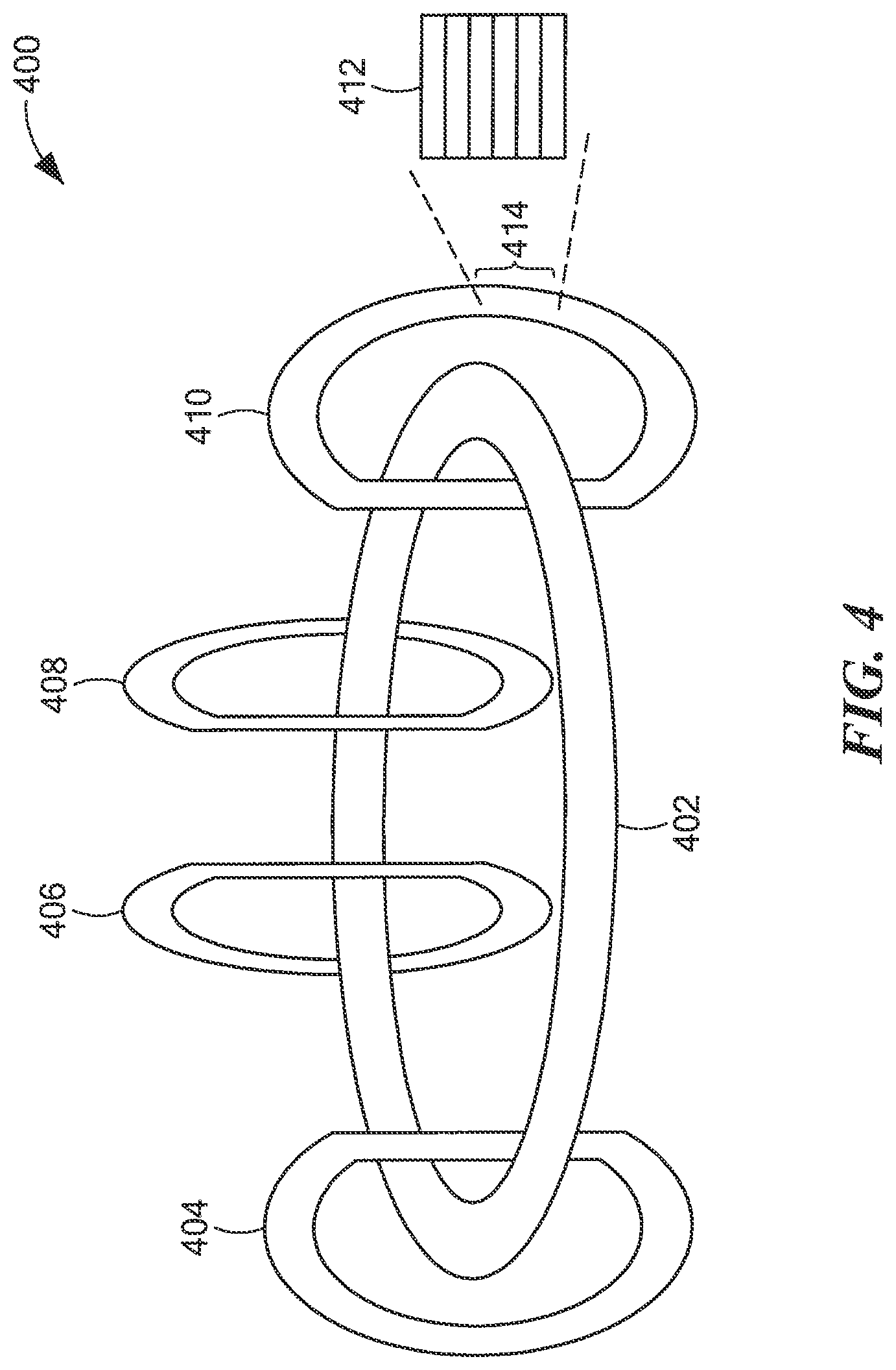
[0060] The control systems described above may be used for various embodiments including, but not limited to fusion power systems. As an example, FIG. 4 is a diagram of a simplified tokamak system 400 for producing fusion power. The diagram includes a plasma tube 402 and a plurality of superconducting magnetic coils 404-410. These coils may be the same as or similar to magnetic coil 102 described above.
[0061] During energy generation, high temperature plasma (which fuels the fusion reaction) circulates within plasma tube 402. Because the plasma is at such high temperatures, if it were to contact the walls of plasma tube 402 it could destroy plasma tube 402. Thus, system 400 generates magnetic fields that compress and suspend the plasma into a stream within plasma tube 402 that does not contact the walls of plasma tube 402.
[0062] To generate the magnetic field, tokamak system 400 has a plurality of magnetic coils 404-410. These coils may comprise superconducting magnets to produce the magnetic field that suspends and compresses the plasma stream.
[0063] In embodiments, each magnetic coil 404-410 includes a series of stacked plates 412. Each stacked plate may enclose a superconducting magnet made from a coil of superconducting tape material. As current flows through the coil of superconducting tape, a magnetic field is generated.
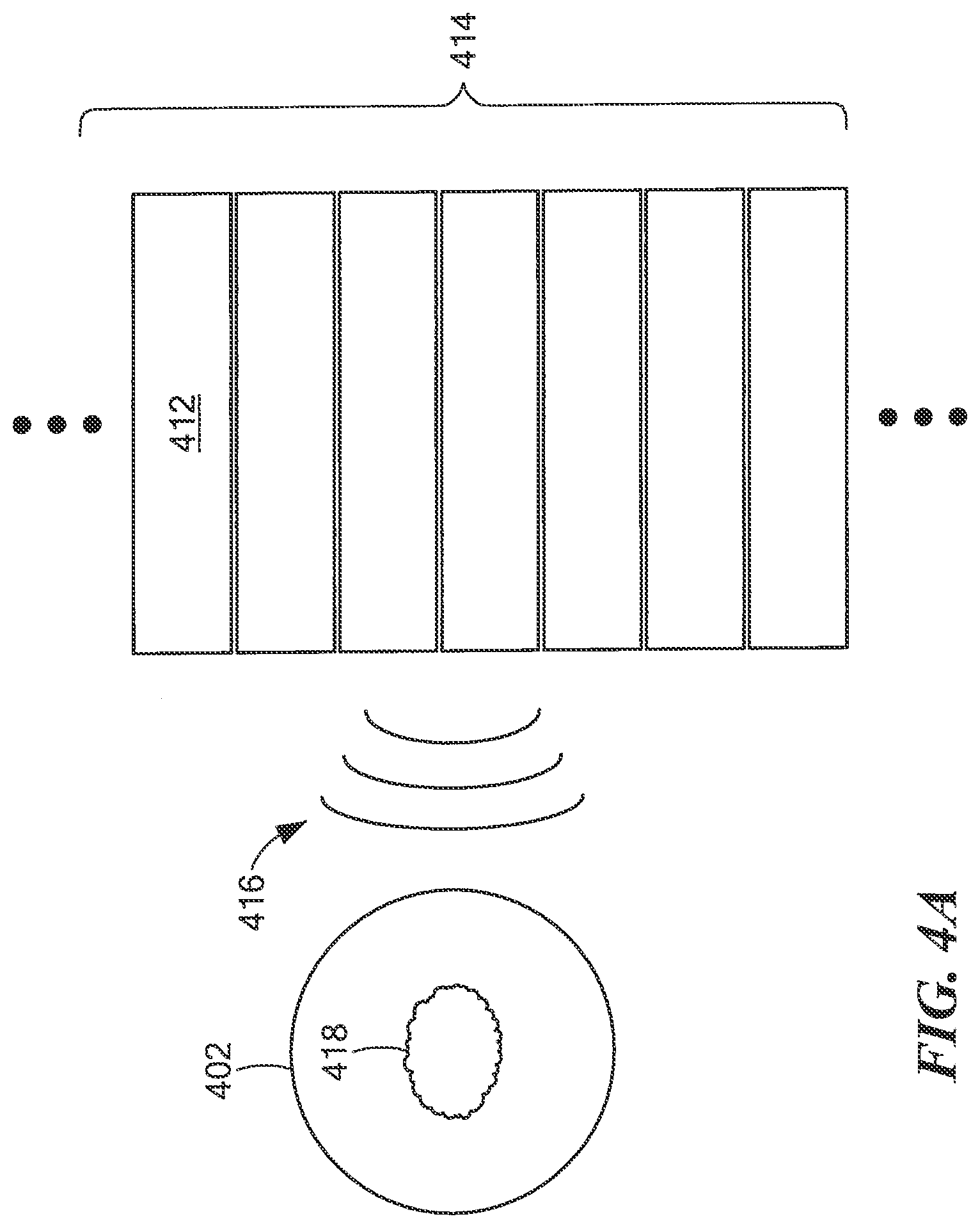
[0064] FIG. 4A is a diagram of a portion 414 of magnetic coil 410. As illustrated, magnetic coil 410 may comprise a series of stacked plates 412. Each plate may contain a superconducting magnet, which may be in the form of a coil, such as a coiled wire or tape for example. Driving electrical current through the superconducting tape may generate a magnetic field 416 that can compress plasma stream 418 so that the plasma does not contact plasma tube 402.
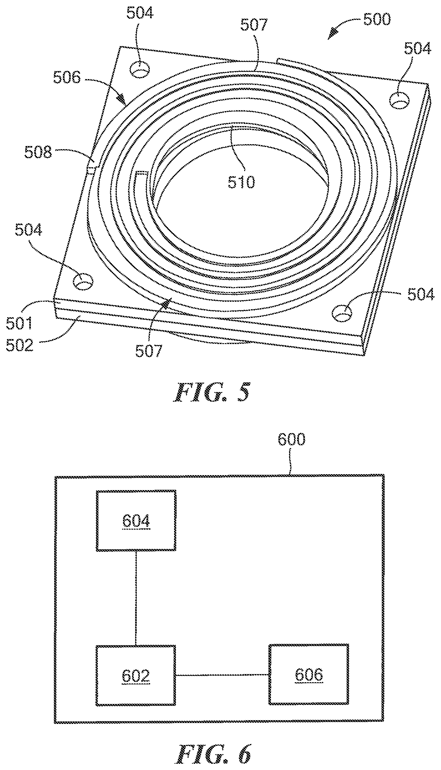
[0065] Referring now to FIG. 5, shown is an example of spiral-grooved plates stacked to form a so-called "double-pancake" assembly 500. In this illustration, two identical spiral-grooved plates 501, 502 are coupled back-to-back with an insulating material (not visible in FIG. 5) inserted or otherwise disposed therebetween. Spiral-grooved, stacked-plate superconducting magnets and related spiral plates which may be the same as or similar to assembly 500 are described in co-pending application Ser. No. 16/233,410 filed on Dec. 27, 2018 and application Ser. No. 16/416,781 filed on May 20, 2019 each of which are assigned to the assignee of the present application and each of which applications are hereby incorporated herein by reference in their entireties.
[0066] In the illustrative embodiment of FIG. 5, a first plate 501 is disposed over a second plate 502 such that interface apertures 504 are aligned and can be used to fasten the plates together. Plate 501 includes a spiral channel 506 defined by walls 507. Channel 506 (also sometimes referred to herein as a grooved path or a groove 506) is provided having a shape (i.e. a channel length, a channel width and a channel height) selected to receive a tape 508.
[0067] Tape 508 may be provided as a high temperature superconductor (HTS) tape stack that may include co-wind materials is inserted into the grooved channel which executes an in-going spiral on the top plate, a helix down to the bottom plate, and an out-going spiral on the bottom plate. In embodiments, tape 508 may be the same as or similar to the superconducting tape described in co-pending applications 62/740,163 filed on Oct. 2, 2018, Ser. No. 16/233,410 filed on Dec. 27, 2018 and application Ser. No. 16/416,781 filed on May 20, 2019 each of which are assigned to the assignee of the present application and each of which applications are hereby incorporated herein by reference in their entireties.
[0068] In some embodiments, tape 508 is continuously wound (i.e. without breaks or segmentation) from a top surface to a bottom surface of the pancake assembly. In some embodiments, tape 508 may be provided as a non-insulating (NI) HTS tape (and co-wind stack when used) which may be segmented or otherwise have breaks provided therein (e.g. the path of one material may be broken and not continuous). It should thus be appreciated that while the channel may be described as more or less continuous (even though a cross-sectional shape of a channel may change throughout the length of the channel), the material loaded or otherwise disposed in the channel may be continuous or may be provided in parts (e.g. segmented).
[0069] In some embodiments, more than one HTS tape stack may be disposed into the groove, with a material disposed between stacks that may engage mechanically with the plate, such as via spiral grooves, separately or in conjunction with the tape stacks. In some embodiments, some or all of the co-wind materials may be disposed to engage with the plate mechanically, such as via spiral grooves, separately or in conjunction with the tape stacks. The co-wind materials and surface coatings may be chosen to provide a desired (and ideally, an optimized) magnet quench behavior.
[0070] Assembly 500 is suitable for use in providing a superconducting magnet assembly such as may be used in any of the applications described herein.
[0071] Similar to plate 501, plate 502 has a tape 510 disposed in a channel thereof. In embodiments, tape 508 and tape 510 may be electrically coupled in series to form a longer winding of tape.
[0072] In embodiments, a superconducting magnet may be configured to operate without any turn-to-turn insulation. In other words, turns of tape 508 may be coiled atop each other and/or separated by a conductive material such as the material from which plates 501, 502 are provided.
[0073] When conditions are met such that tape 508 exhibits superconducting properties, its resistance to current may be ideally zero and in any event much lower than the resistance of normal conductors (conductors which do not exhibit superconducting properties) such as the material (e.g. metal) from which plates 501, 502 are provided. Under these conditions of relatively low voltages in the magnet, current is confined to and flows primarily through the path defined by the channel in which tape 508 lies (i.e. the current flows though the superconductor) and a relatively small amount of current (and ideally no current) will pass from turn to turn of tape 508 (i.e. current will not flow across walls 507 which define the channels in which the tape 508, 510 lies and which separate the turns tape 508. 510).
[0074] If, however, conditions change so that, during operation, superconducting properties are lost (lost either in-whole or in-part), current may begin to flow from turn to turn of the magnet, in a direction shown by arrow 512 instead of flowing around the coil. This phenomenon, when the tape loses its superconducting properties and the current begins to flow from turn-to-turn, may be referred to as quenching.
[0075] Referring to FIG. 6, some or all of the algorithms associated with control circuits 100 and 300, cooling control circuit 306, and/or current control circuit 310 may be implemented as software executing on a computing device, such as computing device 600. Computing device 600 may be a computer, a microprocessor, a custom processing circuit, an FPGA, or any type of circuit or computing device that can execute software instructions.
[0076] Computing device 600 includes a processor 602, a random-access memory (RAM) 604, and a storage device 606, which may be a hard drive, a CD, a DVD, a flash drive, or any other type of non-volatile memory. Software instructions may be stored in RAM 604 and/or storage device 606. Processor 602 may be coupled to storage device 606 and/or RAM 604 so that processor 602 can read the software instructions. As processor 602 reads the software instructions, the software instructions may cause processor 602 to perform operations, as described above in relation to control circuit 302 and/or control circuit 101, for operating a magnetic coil. Although not shown, processor 602 and/or computing device 600 may include other inputs and outputs, such as inputs for receiving the signals from the sensing elements, GPIO, power inputs, or other interfaces such as USB, SATA, HDMI, and the like.
[0077] In a system with multiple superconducting magnets, a number of these control systems may be coupled together.
[0078] In embodiments, the concepts described may facilitate commercialization of high-field magnets for use in fusion power plants (e.g. compact fusion power plants) as well as in high-energy physics applications. However, after reading the description provided herein, one of ordinary skill in the art will readily appreciate that the disclosed concepts are generally applicable for use in a wide range of other applications (e.g. a wide range of industrial uses) which may make use of high-field magnets. Such applications include but are not limited to: applications in the medical and life sciences field (e.g. magnetic resonance imaging and spectroscopy); applications in the chemistry, biochemistry and biology fields (e.g. nuclear magnetic resonance (NMR), NMR spectroscopy, electron paramagnetic resonance (EPR), and Fourier-transform ion cyclotron resonance (FT-ICR)); applications in particle accelerators and detectors (e.g. for use in health care applications such as in instruments for radiotherapy); application in devices for generation and control of hot hydrogen plasmas; applications in the area of transportation; applications in the area of power generation and conversion; applications in heavy industry; applications in weapons and defense; and applications in the area of high energy particle physics.
[0079] As noted above, although reference is sometimes made herein to the use of such high-field magnet assemblies in connection with fusion power plants (e.g. compact fusion power plants) and fusion research experiments (e.g. SPARC), such references are not intended to be, and should not be construed as, limiting. It is appreciated that control circuits and techniques provided in accordance with the concepts described herein for use in and with high-field magnet assemblies find use in a wide variety of different applications
[0080] For example, in the medical and life sciences field, high-field magnets provided in accordance with the concepts described herein may find use in magnetic resonance imaging (MRI) and spectroscopy.
[0081] Referring to FIG. 7, an MRI system 700 comprises a patient table 702 on which the patient is delivered into a tube 703 defined by MRI system 700 for scanning. A scanner 704 uses magnets 706, radio frequency (RF) coils 708, and gradient coils 710 to create images. Maintaining such a large magnetic field requires a good deal of energy, which can be accomplished by using superconductive circuits. Thus, in embodiments, magnets 706 can be superconducting magnets controlled by a control circuit which may be the same as or similar to the control circuits described above in conjunction with FIGS. 1 and 3. In this way, MRI system 700 may be configured to use a strong magnetic field and radio waves to create detailed images of organs and tissues within a person's body.
[0082] Various embodiments are described in this patent. However, the scope of this patent should not be limited to the described embodiments, but rather should be limited only by the spirit and scope of the following claims. All references cited in this patent are incorporated by reference in their entirety.
* * * * *
D00000
D00001
D00002
D00003
D00004
D00005
D00006
D00007
XML
uspto.report is an independent third-party trademark research tool that is not affiliated, endorsed, or sponsored by the United States Patent and Trademark Office (USPTO) or any other governmental organization. The information provided by uspto.report is based on publicly available data at the time of writing and is intended for informational purposes only.
While we strive to provide accurate and up-to-date information, we do not guarantee the accuracy, completeness, reliability, or suitability of the information displayed on this site. The use of this site is at your own risk. Any reliance you place on such information is therefore strictly at your own risk.
All official trademark data, including owner information, should be verified by visiting the official USPTO website at www.uspto.gov. This site is not intended to replace professional legal advice and should not be used as a substitute for consulting with a legal professional who is knowledgeable about trademark law.