Method And Apparatus For Configuring A Plurality Of Virtual Buttons On A Device
LORENZ; Thomas ; et al.
U.S. patent application number 16/903898 was filed with the patent office on 2020-12-24 for method and apparatus for configuring a plurality of virtual buttons on a device. This patent application is currently assigned to Cirrus Logic International Semiconductor Ltd.. The applicant listed for this patent is Cirrus Logic International Semiconductor Ltd.. Invention is credited to Anthony Stephen DOY, Thomas LORENZ.
| Application Number | 20200401292 16/903898 |
| Document ID | / |
| Family ID | 1000004943374 |
| Filed Date | 2020-12-24 |


| United States Patent Application | 20200401292 |
| Kind Code | A1 |
| LORENZ; Thomas ; et al. | December 24, 2020 |
METHOD AND APPARATUS FOR CONFIGURING A PLURALITY OF VIRTUAL BUTTONS ON A DEVICE
Abstract
Embodiments described herein relate to methods and apparatuses for configuring a plurality of virtual buttons on a device. For example, each of the plurality of virtual buttons may be activated or deactivated based on a mode of operation of the device. By activating and deactivating different combinations of the plurality of virtual buttons depending on the mode of operation of the device, the inadvertent engagement of virtual buttons which would otherwise not be used in that mode operation may be avoided.
| Inventors: | LORENZ; Thomas; (Austin, TX) ; DOY; Anthony Stephen; (Los Gatos, CA) | ||||||||||
| Applicant: |
|
||||||||||
|---|---|---|---|---|---|---|---|---|---|---|---|
| Assignee: | Cirrus Logic International
Semiconductor Ltd. Edinburgh GB |
||||||||||
| Family ID: | 1000004943374 | ||||||||||
| Appl. No.: | 16/903898 | ||||||||||
| Filed: | June 17, 2020 |
Related U.S. Patent Documents
| Application Number | Filing Date | Patent Number | ||
|---|---|---|---|---|
| 62864649 | Jun 21, 2019 | |||
| Current U.S. Class: | 1/1 |
| Current CPC Class: | G06F 3/016 20130101; G06F 3/167 20130101; G06F 3/0412 20130101; G06F 3/04142 20190501 |
| International Class: | G06F 3/041 20060101 G06F003/041; G06F 3/01 20060101 G06F003/01; G06F 3/16 20060101 G06F003/16 |
Claims
1. A method for configuring a plurality of virtual buttons on a device, the method comprising: receiving a first signal indicating a mode of operation of the device; outputting a first control signal operable to activate or deactivate each of the plurality of virtual buttons on the device respectively based on the mode of operation of the device; and responsive to receiving a second signal indicating that one of the plurality of virtual buttons that is activated has been engaged by a user of the device, outputting a second control signal operable to initiate a first haptic, visual or audible response corresponding to the one of the plurality of virtual buttons.
2. The method of claim 1 wherein the one or more virtual buttons comprise one or more of: a capacitive sensor, a force sensor, a resistive deflection sensing array or an inductive sensor.
3. The method of claim 1 wherein the first haptic or audible response is configured to indicate a location of the one of the plurality of virtual buttons.
4. The method of claim 3 wherein the second signal indicates that one of the plurality of virtual buttons that is activated has been engaged by a user of the device in a first mode of engagement.
5. The method of claim 4 wherein the one of the plurality of virtual buttons is engaged in the first mode of engagement when the user touches the location of the one of the plurality of virtual buttons.
6. The method of claim 1 wherein the method further comprises: responsive to receiving a third signal indicating that the one of the plurality of buttons has been engaged by a user of the device in a second mode of engagement, outputting a third control signal operable to initiate a second haptic or audible response corresponding to the one of the plurality of virtual buttons.
7. The method of claim 6 wherein the one of the plurality of virtual button is engaged in the second mode of engagement when the user applies pressure to the location of the one of the plurality of virtual buttons.
8. The method of claim 6 further comprising generating the second haptic response such that the second haptic or audible response simulates a button click corresponding to the one of the plurality of virtual buttons that has been engaged in the second mode of engagement.
9. The method of claim 1 wherein the method further comprises: responsive to receiving a plurality of second signals indicating that more than one of the plurality of buttons has been engaged by the user of the device within a predetermined time, outputting a fourth control signal operable to initiate a third haptic or audible response corresponding to said virtual buttons that have been engaged.
10. The method of claim 1 wherein the mode of operation comprises an application running on the device, for example: a phone application, a camera application, a music playback application, a video playback application, a gaming application, an email application.
11. The method of claim 10 wherein the mode of operation comprises a status of the application running on the device.
12. The method of claim 1 wherein the first control signal may be based on a user defined characteristic.
13. The method of claim 1 wherein the second signal is received from a touch screen controller.
14. A control circuit for controlling a plurality of virtual buttons on a device, wherein the control circuit is configured to: receive a first signal indicating of a mode of operation of the device; output a first control signal to activate or deactivate each of the plurality of virtual buttons on the device respectively based on the mode of operation of the device; and responsive to receiving a second signal indicating that one of the plurality of virtual buttons that is activated has been enabled by a user of the device, output a second control signal operable to initiate output of a first haptic, visual or audible response corresponding to the one of the plurality of virtual buttons.
15. An integrated circuit comprising a control circuit for controlling a plurality of virtual buttons on a device, wherein the control circuit configured to: receive a first signal indicating of a mode of operation of the device; output a first control signal to activate or deactivate each of the plurality of virtual buttons on the device respectively based on the mode of operation of the device; and responsive to receiving a second signal indicating that one of the plurality of virtual buttons that is activated has been enabled by a user of the device, outputting a second control signal operable to initiate output of a first haptic, visual or audible response corresponding to the one of the plurality of virtual buttons.
16. A device comprising a control circuit for controlling a plurality of virtual buttons on the device, wherein the control circuit is configured to: receive a first signal indicating of a mode of operation of the device; output a first control signal to activate or deactivate each of the plurality of virtual buttons on the device respectively based on the mode of operation of the device; and responsive to receiving a second signal indicating that one of the plurality of virtual buttons that is activated has been enabled by a user of the device, output a second control signal operable to initiate output of a haptic, visual or audible response corresponding to the one of the plurality of virtual buttons.
17. The device as claimed in claim 16 further comprising the plurality of virtual buttons.
18. The device as claimed in claim 17 wherein the plurality of virtual buttons are located on at least one first surface of the device.
19. The device as claimed in claim 18 wherein a second surface of the device comprises a touch screen display.
20. The device as claimed in claim 18 wherein the at least one first surface each comprise a non-display surface.
21. The device as claimed in claim 17 wherein the plurality of virtual buttons are visually hidden from the outside of the device when assembled.
22. The device of claim 16 wherein the mode of operation of the device comprises an application running on the device, for example: a phone application, a camera application, a music playback application, a video playback application, a gaming application, an email application.
23. The device of claim 22 wherein the mode of operation of the device comprises a status of the application running on the device.
Description
TECHNICAL FIELD
[0001] Embodiments described herein relate to methods and apparatus for configuring a plurality of virtual buttons on a device. For example, each of the plurality of virtual buttons may be activated or deactivated based on a mode of operation of the device.
BACKGROUND
[0002] Physical or mechanical buttons, which are sometimes called hardware or traditional buttons, typically operate through hardware components that physically move upon being pressed and which typically operate like a switch. These buttons are known in the art and are used in a variety of applications. For example, mechanical buttons may be found on the sides of current smart phones to control volume and other settings. Those buttons are readily identifiable both visually and by touch--typically they are set apart from the surrounding device surface and protrude slightly so a user can easily feel their location and engage them with a press. Softkeys and different types of virtual buttons, which are not directly engaged via moving parts of a physical button, are also known in the art. For instance, a touch-sensitive area may act as a virtual button on a smart phone display, and a familiar example of this is the implementation of a virtual keyboard on the touch screen of a smart phone. Advantageously, virtual buttons may be programmed or changed easily through the use of software. Advantageously, virtual buttons may reduce or eliminate hardware related problems experienced by physical buttons, such as mechanical failure after prolonged use, difficulty in waterproofing, and other issues known in the art. In addition to virtual buttons integrated with a touch screen, other types of virtual buttons may reside on a housing or non-screen surface of a device. For example, instead of a traditional button on a surface such as a dashboard, one may use a variety of force sensors, inductive sensors, or similar technology to create a touch-responsive area that acts as a virtual button and does not visually appear to be a traditional physical button.
[0003] US2013/0275058 discloses a handheld portable electronic device, having a display screen and a framing structure, wherein the framing structure includes a strain gauge, for detecting strain within the framing structure. Thus, gestures, such as squeezing the sides of the device, can be recognized, and can be used as inputs to control an application running on the device.
SUMMARY
[0004] According to some embodiments, there is provided a method for configuring a plurality of virtual buttons on a device. The method comprises receiving a first signal indicating a mode of operation of the device; outputting a first control signal operable to activate or deactivate each of the plurality of virtual buttons on the device respectively based on the mode of operation of the device; and responsive to receiving a second signal indicating that one of the plurality of virtual buttons that is activated has been engaged by a user of the device, outputting a second control signal operable to initiate a first haptic or audible response corresponding to the one of the plurality of virtual buttons.
[0005] According to some embodiments there is provided a control circuit for controlling a plurality of virtual buttons on a device. The control circuit is configured to receive a first signal indicating of a mode of operation of the device; output a first control signal to activate or deactivate each of the plurality of virtual buttons on the device respectively based on the mode of operation of the device; and responsive to receiving a second signal indicating that one of the plurality of virtual buttons that is activated has been enabled by a user of the device, output a second control signal operable to initiate output of a first haptic or audible response corresponding to the one of the plurality of virtual buttons.
[0006] According to some embodiments there is provided an integrated circuit comprising a control circuit for controlling a plurality of virtual buttons on a device. The control circuit configured to: receive a first signal indicating of a mode of operation of the device; output a first control signal to activate or deactivate each of the plurality of virtual buttons on the device respectively based on the mode of operation of the device; and responsive to receiving a second signal indicating that one of the plurality of virtual buttons that is activated has been enabled by a user of the device, outputting a second control signal operable to initiate output of a first haptic or audible response corresponding to the one of the plurality of virtual buttons.
[0007] According to some embodiments there is provided a device comprising a control circuit for controlling a plurality of virtual buttons on a device. The control circuit configured to receive a first signal indicating of a mode of operation of the device; output a first control signal to activate or deactivate each of the plurality of virtual buttons on the device respectively based on the mode of operation of the device; and responsive to receiving a second signal indicating that one of the plurality of virtual buttons that is activated has been enabled by a user of the device, outputting a second control signal operable to initiate output of a haptic or audible response corresponding to the one of the plurality of virtual buttons.
[0008] Traditionally, the placement of virtual buttons on a device has been on the "front" of the device (for example, on a touch screen), or on a limited number of surfaces specifically designed for the user interface, with the remainder of the device being free from virtual buttons. By positioning the virtual buttons on a limited number of surfaces on a device, the device (which may be portable) may be easily held by a user without inadvertently engaging the virtual buttons.
[0009] Currently, devices, such as smart phones, have a single front surface that might for example be dominated by a touch screen. Other virtual buttons, such as buttons operating through the use of inductive sensors, may be placed below the touch screen to add further operability to the touch screen surface.
[0010] However, while mechanical buttons may be placed elsewhere on the device, the device is usually otherwise free from the presence of virtual buttons.
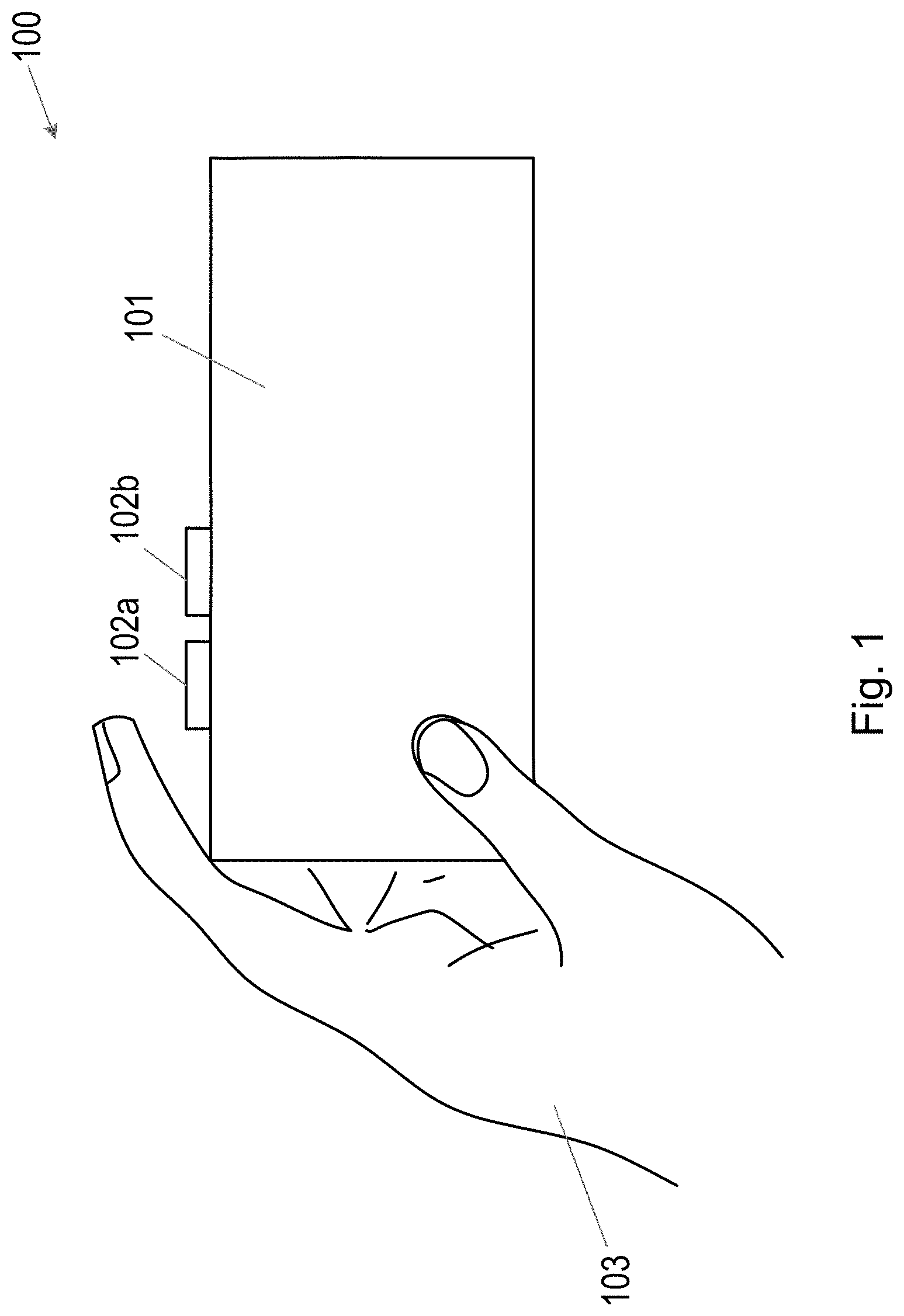
[0011] Should a user want to press a virtual button or indeed the touch screen while using the device, their hands are likely to cover at least a portion of the touch screen surface, which is also acting as a display screen, for example as illustrated in FIG. 1.
[0012] In FIG. 1, a device 100 comprises a touch display screen 101 and mechanical buttons 102a and 102b. As is illustrated, the user's hands 103 have to be over the touch display screen in order to utilize the user interface. In other embodiments, a device may be associated with industrial equipment, automobiles, or any other structure in which a mechanical or virtual button may be of use.
[0013] This configuration may be undesirable in some modes of operation of the device as it may obscure information being displayed by the touch display screen.
BRIEF DESCRIPTION OF THE DRAWINGS
[0014] For a better understanding of the embodiments, and to show how they may be put into effect, reference will now be made, by way of example only, to the accompanying drawings, in which:
[0015] FIG. 1 illustrates a device comprising a touch display screen and mechanical buttons in accordance with the prior art;
[0016] FIG. 2a illustrates a front view of a device in accordance with some embodiments;
[0017] FIG. 2b illustrates a back view of a device in accordance with some embodiments;
[0018] FIG. 3 illustrates a block diagram of a device in accordance with some embodiments;
[0019] FIG. 4 illustrates a method for configuring a plurality of virtual buttons on a device;
[0020] FIG. 5 illustrates an example of a device operating in an email mode of operation; and
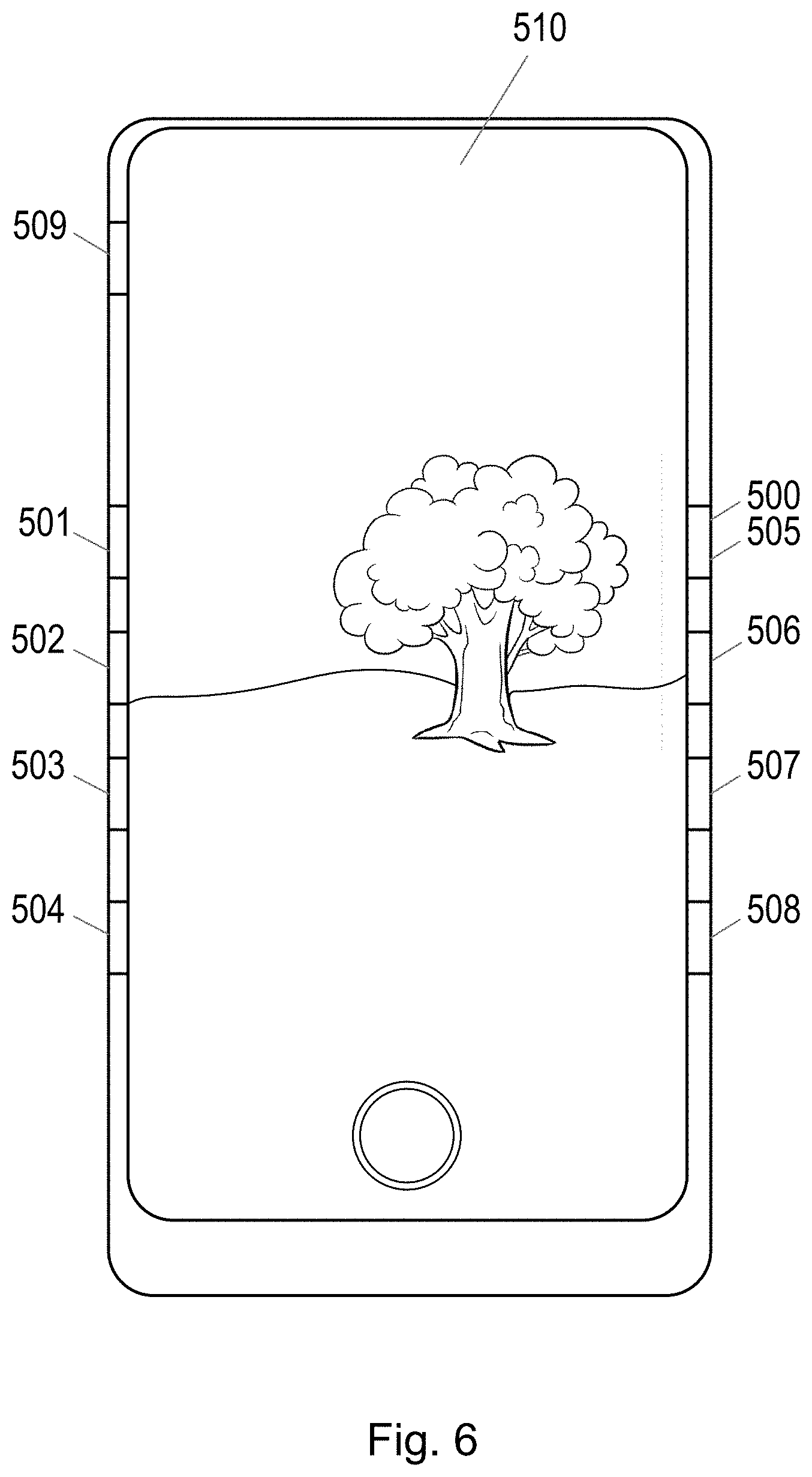
[0021] FIG. 6 illustrates an example of the device 500 operating in a camera mode of operation.
EXAMPLE EMBODIMENTS OF THE PRESENT DISCLOSURE
[0022] The description below sets forth example embodiments according to this disclosure. Further example embodiments and implementations will be apparent to those having ordinary skill in the art. Further, those having ordinary skill in the art will recognize that various equivalent techniques may be applied in lieu of, or in conjunction with, the embodiments discussed below, and all such equivalents should be deemed as being encompassed by the present disclosure.
Description
[0023] The steps of any methods disclosed herein do not have to be performed in the exact order disclosed, unless a step is explicitly described as following or preceding another step and/or where it is implicit that a step must follow or precede another step. Any feature of any of the embodiments disclosed herein may be applied to any other embodiment, wherever appropriate. Likewise, any advantage of any of the embodiments may apply to any other embodiments, and vice versa. Other objectives, features and advantages of the enclosed embodiments will be apparent from the following description.
[0024] Some of the embodiments contemplated herein will now be described more fully with reference to the accompanying drawings. Other embodiments, however, are contained within the scope of the subject matter disclosed herein, and the disclosed subject matter should not be construed as limited to only the embodiments set forth herein; rather, these embodiments are provided by way of example to convey the scope of the subject matter to those of ordinary skill in the art.
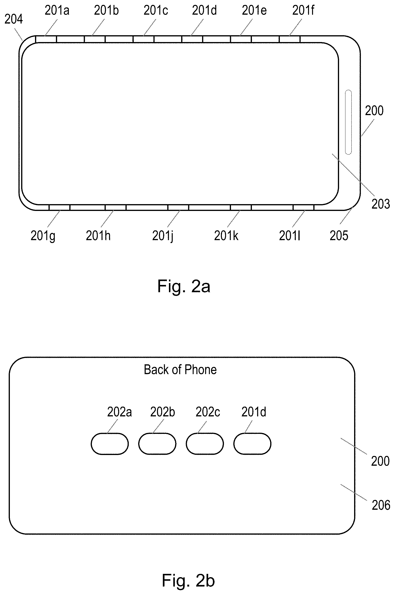
[0025] FIG. 2a illustrates a front view of a device 200.
[0026] The device 200 comprises a touch screen display 203. The device 200 also comprises a plurality of virtual buttons 201a to 201l which, in this example, are situated along the sides of the device 200. For example, the plurality of virtual buttons 201a to 201l may be located on a non-display surface of the device 200. The non-display surface may be metallic or other materials known in the art suitable to form a housing or other structure associated with the device 200.
[0027] In this example, the device 200 comprises a smart phone, and the plurality of virtual buttons 201a to 201l are located on the sides 204 and 205 of the device 200.
[0028] FIG. 2b illustrates a back view of the device 200.
[0029] In this example, the back surface 206 of the device 200 comprises a plurality of virtual buttons 202a to 202d.
[0030] It will be appreciated that any surface of the device may comprise a virtual button. In particular, any non-display surface of the device may comprise a virtual button.
[0031] The virtual buttons may operate through the use of force sensors, inductive sensors, capacitive sensors, a resistive deflection sensing array, or any other mechanism configured to define a touch-sensitive area, or any combination of such mechanisms. It will be apparent that any type of virtual button used to replace a mechanical button may be used in the embodiments of this disclosure.
[0032] The plurality of virtual buttons may be visually hidden in or on the device. For example, when looking at the back or side surfaces of the device 200, a user may not be able to see the presence of the plurality of virtual buttons, and the location of the plurality of virtual buttons may not be otherwise visually or tactilely indicated. In different embodiments, the presence of the virtual buttons may be hidden only when the device is powered off. In the off state, one or more of the virtual buttons may be flush with, and otherwise visually and tactilely indistinguishable from, the rest of the device's casing or surrounding area. Upon powering on, or in specific modes of operation, however, one or more virtual buttons may be made detectable through the use of lighting, sound, or haptics (as described more fully below), or other techniques that will be apparent to those having ordinary skill in the art. Advantageously, the use of virtual buttons indistinguishable from other portions of a device in use may create a cleaner look for the device and may effectively create a highly configurable device without cluttering its physical appearance or feel, as will be more apparent with the benefit of this disclosure.
[0033] FIG. 3 illustrates a block diagram of a device 300. The device 300 may comprise a plurality of virtual buttons as illustrated in FIGS. 2a and 2b.
[0034] Device 300 comprises control circuitry 301. The control circuitry 301 may be configured to communicate with an Applications Processor 302 and/or an orientation module 303. Applications Processor 302 may determine, or help determine, a mode of operation of the device as described more fully below. Orientation module 303 may be hardware and/or software based and in one embodiment may comprise an accelerometer, inertia sensor, or other sensor configured to signal a device's orientation, such as portrait or landscape mode. In other embodiments, the orientation module 303 may act more generally as a context-aware module. For example, it may determine characteristics such as whether a device is placed flat on a table, held within a purse or pocket (via a light-based sensor), being transported at high speed, etc. The control circuitry 301 may also be configured to communicate with a virtual button controller 304.
[0035] The virtual button controller 304 may be configured to control the virtual buttons 305. The virtual buttons 305 may be positioned around the device or on other surfaces, for example, as illustrated in FIGS. 2a and 2b.
[0036] The control circuitry 301 may be configured to perform a method as illustrated in FIG. 4.
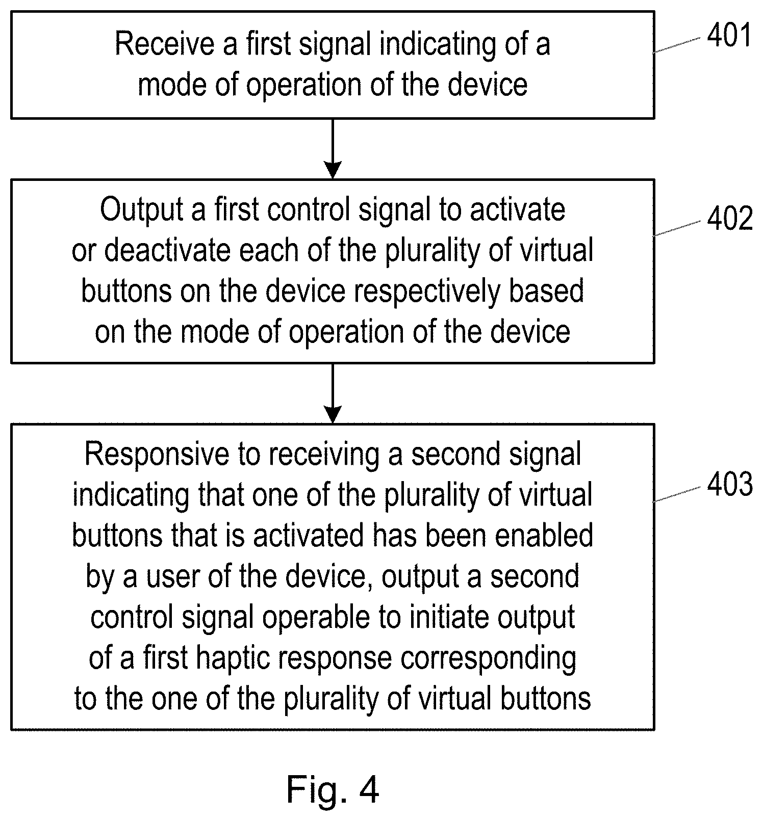
[0037] FIG. 4 illustrates a method for configuring a plurality of virtual buttons on a device.
[0038] In step 401, the control circuitry is configured to receive a first signal indicating a mode of operation of the device. For example, the first signal may comprise a signal S.sub.1 received from the applications processor 302. The first signal S.sub.1 may indicate a particular application that is running on the device, for example a phone application, a gaming application, a camera application, an email application, a music playback application, a video playback application etc. In addition, the first signal S.sub.1 may indicate a mode of operation in the form of a status of an application that is running on the device. For example, when an email application is running, the first signal S.sub.1 may indicate whether the device display is showing a list of emails, from which the user may select one email to read, or whether the device display is showing a box in which the user may compose a new email.
[0039] The first signal may additionally or alternatively comprise a signal S.sub.2 received from the orientation module 303. The signal S.sub.2 may indicate the orientation of the device 300 and may originate from, for example, a gyroscope and/or an accelerometer, which may provide a corresponding signal to the orientation module 303.
[0040] In some examples, the mode of operation may additionally or alternatively comprise a user defined characteristic. For example, the mode of operation may also indicate whether or not the user is left or right handed or any setting or characteristic that is distinguishable from a different setting or characteristic during operation.
[0041] Therefore, in different embodiments, the mode of operation of the device may comprise an application running on the device, a characteristic or parameter within or associated with such application, an orientation of the device, a user defined characteristic, or other modes associated with the device or its user interface or its software as would be understood by those having ordinary skill in the art. For example, a mode of operation may be defined not only with respect to which app is being run on a device, but also with respect to one or more particular actions being taken within an individual app.
[0042] In step 402, the control circuitry is configured to output a first control signal C.sub.1 to activate or deactivate each of the plurality of virtual buttons on the device based on the mode of operation of the device. If a virtual button is activated, then responsive to sensing a touch or press from a user, the virtual button may transmit a signal to the virtual button controller. If a virtual button is deactivated, then, for example, either the virtual button may be placed in a state of operation in which it does not sense the touch or press of a user, or the signals transmitted to the virtual button controller may be completely or partially ignored as a result of the deactivated state of the virtual button.
[0043] For example, when a virtual button is deactivated, if the deactivated virtual button is touched or pressed by a user, then there may be no operation performed by the device in response.
[0044] By activating and deactivating different combinations of the plurality of virtual buttons depending on the mode of operation of the device, the inadvertent engagement of virtual buttons which would otherwise not be used in that mode operation may be avoided. Additionally, combinations of virtual buttons may be activated or deactivated together to create unique user interfaces. For example, two or more adjoining or nearby virtual buttons may be activated together, that is, within a predetermined time of each other, and those activated buttons may act in concert to implement a different user interface feature, such as a virtual scroll bar as discussed more fully below. In such an embodiment, a user may swipe across the group of virtual buttons that, together, act as one larger button to scroll content on a screen or some other functionality.
[0045] The first control signal C.sub.1 may be output to the virtual button controller 304, which may control an operation state of the plurality of virtual buttons. The virtual button controller 304 may, for example, place the plurality of virtual buttons in an activated or deactivated state in response to the control signal C.sub.1, or may ignore signals received from virtual buttons which are deactivated by the control signal C.sub.1.
[0046] For example, referring to the example illustrated in FIGS. 2a and 2b, responsive to the first signal S.sub.1/S.sub.2 indicating that the device is operating in a gaming mode and is orientated as illustrated in FIGS. 2a and 2b, the first control signal C.sub.1 may be configured to activate virtual buttons 201a, 201f, 202a and 202d, and deactivate buttons 201b, 201c, 201d, 201e, 201g, 201h, 201j 201k, 2011, 202b and 202c. However, should the first signal S.sub.1/S.sub.2 indicate that the device is operating in the gaming mode but is orientated with the virtual buttons 201a to 201f closer to the earth, then the first control signal C.sub.1 may be configured to activate virtual buttons 201g, 2011, 202a and 202d, and deactivate buttons 201a, 201b, 201c, 201d, 201e, 201f, 201h, 201j 201k, 202b and 202c.
[0047] It will be appreciated that in some modes of operation, all of the plurality of virtual buttons may be deactivated. For example, when the device is not in use (for example when no applications are actively running on the device), it may be desirable for all of the virtual buttons to be deactivated. Determining the context of the device in this regard may be facilitated by the orientation module 303 of FIG. 3.
[0048] In step 403, the control circuitry 301 is configured to, responsive to receiving a second signal S.sub.L indicating that one of the plurality of virtual buttons that is activated has been enabled by a user of the device, output a second control signal, C.sub.2 operable to initiate output of a first haptic or audible or visual response corresponding to the one of the plurality of virtual buttons. In this embodiment, enabling a button refers to the button being pressed or otherwise touched or activated to initiate a responsive action associated with the device or software running on the device. In a typical embodiment, enabling a virtual button would be akin to pressing a mechanical button, the response to which would be to initiate an action. In other embodiments, however, enabling a virtual button may depend on the degree or the type of press or contact from a user. For example, enabling a button may depend on the amount of pressure applied--a "hard" press may create a different response than a "soft" press, and many different pressure levels may be detected, each of which may be correlated to a different response. In other embodiments, virtual buttons may be enabled via one or more touch gestures (for example, swipe, pinch, tap, two-finger tap, etc.) that may be configured for different responses. More generally, embodiments of this disclosure contemplate any such enablement or activation or similar effect as would be apparent by those having ordinary skill in the art.
[0049] In some examples, a first haptic response may be provided that is associated with one or more of the plurality virtual buttons. According to some embodiments, a haptic response may be any tactile sensation generated in or on the device, and preferably one designed to create an impression that the virtual button itself generated such sensation. In one embodiment, a haptic response may be generated by one or more vibrating motors or linear resonant actuators (LRAs) or similar devices. As is known in the art, haptic responses may be tailored to simulate mechanical button clicks and a host of other sensations including various surface textures, and all such techniques may be used in the embodiments of this disclosure. In other examples, a first haptic response may be provided by a separate haptic device 306. In some examples, a first audible response is provided by a speaker 307. In some examples, a first haptic response and first audible response may be provided together. In other embodiments, a visual response may be provided by a visual indicator 309. For example, the visual response may be fashioned by using LED or other lighting at or near the location of a virtual button to, for example, signal that such button has been enabled or that it has been enabled in a certain manner.
[0050] A virtual button may be enabled by a user when the user in some way touches or presses the location of the virtual button on the surface of the device.
[0051] The first haptic, audible, and/or visual response may be configured to indicate a location of the one of the plurality of virtual buttons that has been activated.
[0052] For example, returning to FIGS. 2a and 2b, when a user places a device into, for example, a gaming mode of operation, they may then use their fingers to locate the activated virtual buttons on the back surface and side surfaces of the device 200. As the user will be looking at the touch screen 203 when utilizing the device 200 in this configuration, it may not be practical in this particular embodiment to utilize visual cues to notify the user as to the location of the activated virtual buttons.
[0053] In step 403, when the user locates the activated virtual button, the user may be notified that they have found the appropriate location on the surface by the first haptic response.
[0054] In some examples however, the location of some or all virtual buttons may additionally or alternatively be notified to a user by an indentation or pattern on the surface of the device, or by some other physical trait of the device, that may be felt by the user at the location of the virtual button.
[0055] In some examples, virtual buttons may be provided in conjunction with a touch screen. For example, the side surfaces 204 and 205 of device 200 may comprise a touch screen 308, as may the back surface. As a user moves their finger along the touch screen to the location of the one of the plurality of virtual buttons, the touch screen 308 may be configured to transmit the second signal S.sub.I to the control circuitry indicating that one of the plurality of virtual buttons that is activated has been enabled by a user of the device. In this example, the virtual button may be enabled by the user placing this finger in the correct position on the surface of the device.
[0056] In some examples, one or more of the plurality of virtual buttons may be sensitive to different types of engagement by the user. For example, a virtual button may be able to distinguish between the user touching the location of the virtual button and the user applying pressure to the location of the virtual button.
[0057] In this example, the activated virtual button may therefore be capable of more than one mode of engagement.
[0058] Therefore, in step 403, the second signal S.sub.L may indicate that one of the plurality of virtual buttons that is activated has been engaged by a user of the device in a first mode of engagement. For example, the one of the plurality of virtual buttons is engaged in the first mode of engagement when the user touches the location of the one of the plurality of virtual buttons without applying any additional pressure, or with a level of pressure below a particular threshold.
[0059] As discussed previously, the first haptic response may then indicate a location of the one of the plurality of virtual buttons to the user.
[0060] In some examples, the control circuitry may be configured to, responsive to receiving a third signal S.sub.p indicating that the one of the plurality of buttons has been engaged by a user of the device in a second mode of engagement, output a third control signal C.sub.3 operable to initiate a second haptic or audible or visual response corresponding to the one of the plurality of virtual buttons. In some examples, a second haptic response may be provided by the one of the plurality virtual buttons. In other examples, the second haptic response may be provided by a separate haptic device 306. In some examples, a second audible response is provided by a speaker 307. In some examples, a second visual response is provided by a visual indicator 309. In some examples, two or more of a second haptic response, a second audible response, and a second visual response may be provided together.
[0061] The one of the plurality of virtual buttons may be engaged in the second mode of engagement when the user applies pressure to the location of the one of the plurality of virtual buttons. For example, the one of the plurality of virtual buttons may be engaged in the second mode of engagement when the user applies a level pressure above a particular threshold to the location of the one of the plurality of virtual buttons.
[0062] The second haptic or audible response may be different to the first haptic or audible response, and in some examples, may simulate a click associated with a traditional or mechanical button press.
[0063] For example, when a user places a device in gaming mode as illustrated in FIG. 2a, the control circuitry may for example activate virtual buttons 201a, 201f, 202a and 202d. These activated virtual buttons may provide specific operations within the gaming mode of the device 200.
[0064] As user holding the device 200 and looking at the touch screen 203 may then locate the activated virtual buttons by running their fingers along the top side edge 204 and back of the device 200. When a finger of the user touches the location of one of the activated virtual buttons (either sensed by the activated virtual button itself or the touch screen 308), the first haptic or audible response may alert the user that they have located an activated virtual button.
[0065] In some examples, the first haptic or audible response may be provided when the user initially touches the location of the activated virtual button, and the first haptic response may not be repeated if the user continues to touch the location of the activated virtual button.
[0066] Once the user has located a virtual button that they wish to use, the user may "press" the virtual button to generate a response within the gaming mode (for example, button 201a may cause an avatar within the game to jump, whereas button 201f may cause the avatar within the game to crouch).
[0067] When the user presses the virtual button, for example, when the user applies a level of pressure above a particular threshold to the location of the virtual button, the user may be alerted that they have pressed the virtual button by the second haptic or audible response.
[0068] In some examples, a virtual button may be configured with the particular threshold and may output a signal when it detects a pressure above the particular threshold to indicate that it has been pressed. In some examples, a touch screen (e.g. touch screen) may be utilized to adjust the particular threshold. For example, the touch screen may detect that the user's finger is close to the virtual button, but not exactly on the location of the virtual button. In this case, the virtual button may still detect pressure from the user, but the virtual button may be configured to lower the level of the particular threshold in order to avoid the user having to apply more pressure in order to trigger the same threshold. The virtual button may be configured by the virtual button controller 304. The virtual button controller 304 may receive an indication of the location of the user's finger from the touch screen 308, and may provide appropriate control of the particular threshold for the virtual button in response.
[0069] It will be appreciated that different types of user interaction may trigger the different modes of engagement of a virtual button. For example, a virtual button may be engaged in a first mode of engagement by a user tapping the location, by a user touching the location of the virtual button for an elongated period of time, by a user dragging their touch across the location of the virtual button, or any other touch pattern that is distinguishable by the virtual button.
[0070] It will also be appreciated that for different modes of operation, different combinations of virtual buttons may be activated, and that in different modes of operation, the same virtual button may provide different operations.
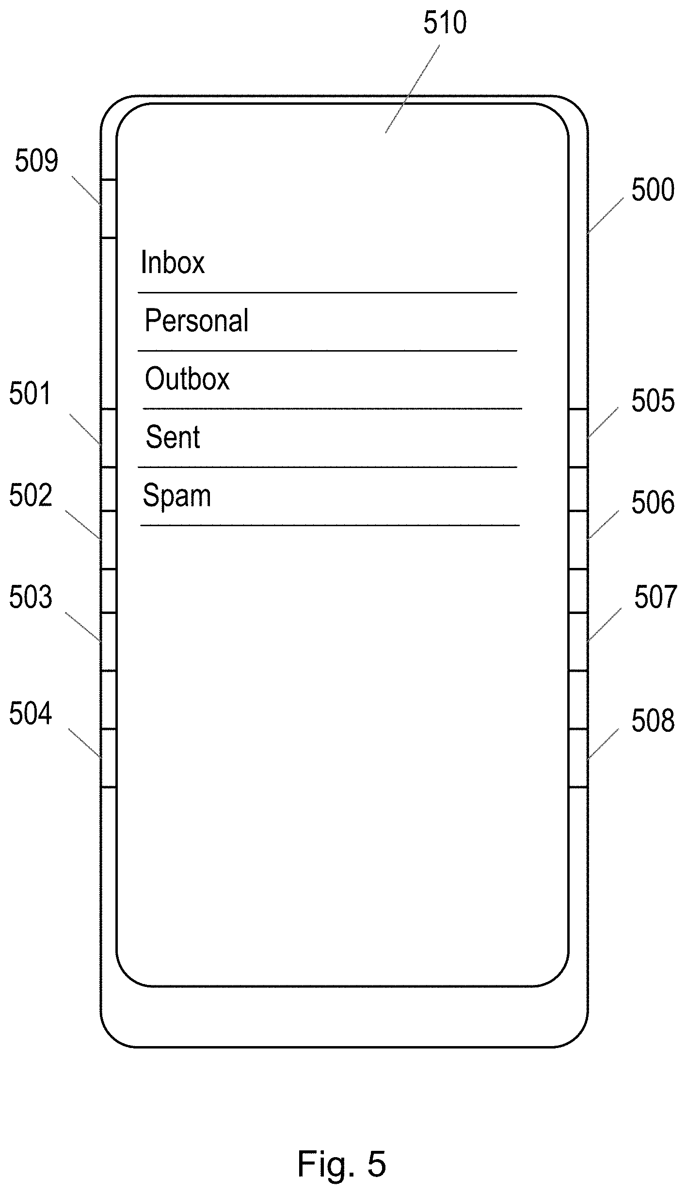
[0071] FIG. 5 illustrates an example of a device 500 operating in an email mode of operation. A display screen 510 is illustrating a list of emails.
[0072] In this example, the first signal may indicate to the control circuitry 301 that an email app has been opened, and that the device is being held in portrait mode, for example as illustrated in FIG. 5. The first signal may also indicate that the user is right or left handed.
[0073] In response to this first signal, the control circuitry may activate virtual buttons 501 to 504 if the first signal indicates that the user is left handed, and may activate virtual buttons 505 to 508 if the first signal indicates that the user is right handed. Any other virtual buttons may be deactivated (for example virtual buttons 509 and 510).
[0074] Consider an example where the user is left handed.
[0075] In this example, the grouping of virtual buttons act in concert, and the user may engage more than one of the virtual buttons within a predetermined time, for example by swiping a finger across the virtual buttons, to cause the email app to scroll up and down through a list of emails. In particular, the user may hold the device 500 in their left hand and may use their thumb to swipe up and down over the four virtual buttons 501 to 504 in turn.
[0076] The virtual buttons 501 to 504 may therefore be effectively implemented as a virtual scroll wheel, and, as the user engages each of the virtual buttons, a haptic or audible response may be provided that simulates a mechanical scroll wheel clicking as it turns.
[0077] It will be appreciated that a single virtual button may be utilized instead of the plurality of virtual buttons to similarly implement a virtual scroll wheel.
[0078] FIG. 6 illustrates an example of the device 500 operating in a camera mode of operation. The display screen 510 is displaying the image currently captured by a camera of the device.
[0079] In this example, the first signal may indicate to the control circuitry 301 that a camera app has been opened and that the device 500 is being held in portrait mode, for example as illustrated in FIG. 6.
[0080] In response to this first signal, the control circuitry may activate virtual buttons 501 to 504 and 509. The virtual buttons 505 to 508 may be deactivated.
[0081] In this example, the same virtual buttons 501 to 504 that were used to scroll up and down through a list of emails in the email mode of operation, may be used to cause the camera to zoom in and out. These virtual buttons may be engaged and a haptic or audible response may be provided as previously described with reference to FIG. 5.
[0082] In addition, in this camera mode, the virtual button 509 is activated. This virtual button may provide two modes of engagement. A first mode of engagement may be used to locate the virtual button, and the second mode of engagement may be used to cause an operation in the application on the device. In some examples, a touch screen may be formed on the surface over the virtual button 509, and may be used to locate the virtual button. For example, the virtual button 509 may be located by the user touching the location of the virtual button 509. As described with reference to FIG. 4, the control circuitry may then initiate output of a first haptic or audible response indicating to the user that the activated virtual button has been located. Once the user has located the virtual button 509, the user may engage the button (for example, to cause the camera to change mode) by applying pressure to the location of the virtual button 509. Again, as described with reference to FIG. 4, the control circuitry may then initiate output of a second haptic or audible response, where the second haptic response may simulate a button press.
[0083] It will be appreciated that the addition of the virtual buttons away from the display screen 510 of the device avoids the use of the display screen as a touch screen, thereby avoiding obscuring information displayed by the display screen 510.
[0084] Embodiments may be implemented in an electronic, portable and/or battery powered host device such as a smartphone, an audio player, a mobile or cellular phone, or a handset. Embodiments may be implemented on one or more integrated circuits provided within such a host device.
[0085] It should be understood--especially by those having ordinary skill in the art with the benefit of this disclosure--that that the various operations described herein, particularly in connection with the figures, may be implemented by other circuitry or other hardware components. The order in which each operation of a given method is performed may be changed, and various elements of the systems illustrated herein may be added, reordered, combined, omitted, modified, etc. It is intended that this disclosure embrace all such modifications and changes and, accordingly, the above description should be regarded in an illustrative rather than a restrictive sense.
[0086] Similarly, although this disclosure makes reference to specific embodiments, certain modifications and changes can be made to those embodiments without departing from the scope and coverage of this disclosure. Moreover, any benefits, advantages, or solutions to problems that are described herein with regard to specific embodiments are not intended to be construed as a critical, required, or essential feature or element.
[0087] Further embodiments likewise, with the benefit of this disclosure, will be apparent to those having ordinary skill in the art, and such embodiments should be deemed as being encompassed herein.
[0088] The skilled person will recognise that some aspects of the above-described apparatus and methods, for example the method as performed by the control circuitry, may be embodied as processor control code, for example on a non-volatile carrier medium such as a disk, CD- or DVD-ROM, programmed memory such as read only memory (Firmware), or on a data carrier such as an optical or electrical signal carrier. For many applications embodiments of the invention will be implemented on a DSP (Digital Signal Processor), ASIC (Application Specific Integrated Circuit) or FPGA (Field Programmable Gate Array). Thus the code may comprise conventional program code or microcode or, for example code for setting up or controlling an ASIC or FPGA. The code may also comprise code for dynamically configuring re-configurable apparatus such as re-programmable logic gate arrays. Similarly the code may comprise code for a hardware description language such as Verilog.TM. or VHDL (Very high speed integrated circuit Hardware Description Language). As the skilled person will appreciate, the code may be distributed between a plurality of coupled components in communication with one another. Where appropriate, the embodiments may also be implemented using code running on a field-(re)programmable analogue array or similar device in order to configure analogue hardware.
[0089] Note that as used herein the term module shall be used to refer to a functional unit or block which may be implemented at least partly by dedicated hardware components such as custom defined circuitry and/or at least partly be implemented by one or more software processors or appropriate code running on a suitable general purpose processor or the like. A module may itself comprise other modules or functional units. A module may be provided by multiple components or sub-modules which need not be co-located and could be provided on different integrated circuits and/or running on different processors.
[0090] It should be noted that the above-mentioned embodiments illustrate rather than limit the invention, and that those skilled in the art will be able to design many alternative embodiments without departing from the scope of the appended claims or embodiments. The word "comprising" does not exclude the presence of elements or steps other than those listed in a claim or embodiment, "a" or "an" does not exclude a plurality, and a single feature or other unit may fulfil the functions of several units recited in the claims or embodiments. Any reference numerals or labels in the claims or embodiments shall not be construed so as to limit their scope.
[0091] Although the present disclosure and certain representative advantages have been described in detail, it should be understood that various changes, substitutions, and alterations can be made herein without departing from the spirit and scope of the disclosure as defined by the appended claims or embodiments. Moreover, the scope of the present disclosure is not intended to be limited to the particular embodiments of the process, machine, manufacture, compositions of matter, means, methods, or steps, presently existing or later to be developed that perform substantially the same function or achieve substantially the same result as the corresponding embodiments herein may be utilized. Accordingly, the appended claims or embodiments are intended to include within their scope such processes, machines, manufacture, compositions of matter, means, methods, or steps.
[0092] As used herein, when two or more elements are referred to as "coupled" to one another, such term indicates that such two or more elements are in electronic communication or mechanical communication, as applicable, whether connected indirectly or directly, with or without intervening elements.
[0093] This disclosure encompasses all changes, substitutions, variations, alterations, and modifications to the example embodiments herein that a person having ordinary skill in the art would comprehend. Similarly, where appropriate, the appended claims encompass all changes, substitutions, variations, alterations, and modifications to the example embodiments herein that a person having ordinary skill in the art would comprehend. Moreover, reference in the appended claims to an apparatus or system or a component of an apparatus or system being adapted to, arranged to, capable of, configured to, enabled to, operable to, or operative to perform a particular function encompasses that apparatus, system, or component, whether or not it or that particular function is activated, turned on, or unlocked, as long as that apparatus, system, or component is so adapted, arranged, capable, configured, enabled, operable, or operative. Accordingly, modifications, additions, or omissions may be made to the systems, apparatuses, and methods described herein without departing from the scope of the disclosure. For example, the components of the systems and apparatuses may be integrated or separated. Moreover, the operations of the systems and apparatuses disclosed herein may be performed by more, fewer, or other components and the methods described may include more, fewer, or other steps. Additionally, steps may be performed in any suitable order. As used in this document, "each" refers to each member of a set or each member of a subset of a set.
[0094] Although exemplary embodiments are illustrated in the figures and described below, the principles of the present disclosure may be implemented using any number of techniques, whether currently known or not. The present disclosure should in no way be limited to the exemplary implementations and techniques illustrated in the drawings and described above.
[0095] Unless otherwise specifically noted, articles depicted in the drawings are not necessarily drawn to scale.
[0096] All examples and conditional language recited herein are intended for pedagogical objects to aid the reader in understanding the disclosure and the concepts contributed by the inventor to furthering the art, and are construed as being without limitation to such specifically recited examples and conditions. Although embodiments of the present disclosure have been described in detail, it should be understood that various changes, substitutions, and alterations could be made hereto without departing from the spirit and scope of the disclosure.
[0097] Although specific advantages have been enumerated above, various embodiments may include some, none, or all of the enumerated advantages. Additionally, other technical advantages may become readily apparent to one of ordinary skill in the art after review of the foregoing figures and description.
[0098] To aid the Patent Office and any readers of any patent issued on this application in interpreting the claims appended hereto, applicants wish to note that they do not intend any of the appended claims or claim elements to invoke 35 U.S.C. .sctn. 112(f) unless the words "means for" or "step for" are explicitly used in the particular claim.
* * * * *
D00000
D00001
D00002
D00003
D00004
D00005
D00006
XML
uspto.report is an independent third-party trademark research tool that is not affiliated, endorsed, or sponsored by the United States Patent and Trademark Office (USPTO) or any other governmental organization. The information provided by uspto.report is based on publicly available data at the time of writing and is intended for informational purposes only.
While we strive to provide accurate and up-to-date information, we do not guarantee the accuracy, completeness, reliability, or suitability of the information displayed on this site. The use of this site is at your own risk. Any reliance you place on such information is therefore strictly at your own risk.
All official trademark data, including owner information, should be verified by visiting the official USPTO website at www.uspto.gov. This site is not intended to replace professional legal advice and should not be used as a substitute for consulting with a legal professional who is knowledgeable about trademark law.