Input Device
CHIU; Shih-Wen ; et al.
U.S. patent application number 16/896561 was filed with the patent office on 2020-12-24 for input device. This patent application is currently assigned to Lite-On Electronics (Guangzhou) Limited. The applicant listed for this patent is Lite-On Electronics (Guangzhou) Limited, LITE-ON Technology Corporation. Invention is credited to Yi-Wen CHEN, Shih-Wen CHIU.
| Application Number | 20200401234 16/896561 |
| Document ID | / |
| Family ID | 1000004888036 |
| Filed Date | 2020-12-24 |


| United States Patent Application | 20200401234 |
| Kind Code | A1 |
| CHIU; Shih-Wen ; et al. | December 24, 2020 |
Input Device
Abstract
The present disclosure provides an input device including a housing, a keyboard assembly, and a first light source. The housing comprises a body and a plurality of sidewalls. The plurality of sidewalls is disposed along the body, forming an accommodating space. The keyboard assembly is disposed in the accommodating space. The first light source is disposed in the body. The light emitted from the first light source emits from the plurality of sidewalls, creating a glowing effect on the periphery of the keyboard assembly. By configuring computer using modes corresponding to the light emitting states, it is possible for users to intuitively discriminate the using patterns.
| Inventors: | CHIU; Shih-Wen; (Taipei City, TW) ; CHEN; Yi-Wen; (Taipei City, TW) | ||||||||||
| Applicant: |
|
||||||||||
|---|---|---|---|---|---|---|---|---|---|---|---|
| Assignee: | Lite-On Electronics (Guangzhou)
Limited Guangzhou City CN LITE-ON Technology Corporation Taipei City TW |
||||||||||
| Family ID: | 1000004888036 | ||||||||||
| Appl. No.: | 16/896561 | ||||||||||
| Filed: | June 9, 2020 |
Related U.S. Patent Documents
| Application Number | Filing Date | Patent Number | ||
|---|---|---|---|---|
| 62863251 | Jun 18, 2019 | |||
| Current U.S. Class: | 1/1 |
| Current CPC Class: | G06F 3/0202 20130101; H01H 13/704 20130101; H01H 13/7057 20130101; H01H 2219/039 20130101; H01H 13/83 20130101 |
| International Class: | G06F 3/02 20060101 G06F003/02; H01H 13/83 20060101 H01H013/83; H01H 13/7057 20060101 H01H013/7057; H01H 13/704 20060101 H01H013/704 |
Claims
1. An input device, comprising: a housing comprising a body and a plurality of sidewalls, wherein the plurality of sidewalls disposed along the body, and connecting to the body, thereby forming an accommodating space; a keyboard assembly disposed in the accommodating space; and a first light source disposed in the body, the light emitted from the first light source emitting through the plurality of sidewalls.
2. The input device according to claim 1, wherein the keyboard assembly comprises: a baseplate; and a plurality of keyswitches disposed on the baseplate; wherein the plurality of sidewalls extends toward the baseplate from the body.
3. The input device according to claim 2, wherein the keyboard assembly further comprises a second light source disposed below the plurality of keyswitches; the light emitted from the second light source emit from the plurality of keyswitches.
4. The input device according to claim 1, wherein the first light source comprises at least one first light emitting element and at least one first light source circuit board; the at least one first light emitting element is disposed on the at least one first light source circuit board.
5. The input device according to claim 4, wherein the at least one first light source circuit board disposed below the body is separated from the body by a distance.
6. The input device according to claim 5, wherein the first light source further comprises at least one light guiding element disposed on the light exit path of the at least one first light emitting element; the light emitted from the at least one first light emitting element is guided by the at least one light guiding element to emit to the plurality of sidewalls.
7. The input device according to claim 6, wherein the number of the at least one first light emitting element is plural; a reflective layer is provided on a surface of the body opposite to the plurality of first light emitting elements.
8. The input device according to claim 6, wherein the at least one light guiding element comprises a light incident surface, a light exit surface, a side surface, and a bottom surface; the light exit surface is opposite to the bottom surface; the light incident surface is connected to the light exit surface; the side surface is connected to the bottom surface; wherein the side surface is provided with a reflective layer or a light shielding layer.
9. The input device according to claim 4, wherein the at least one first light source circuit board disposed below the body is connected to the body.
10. The input device according to claim 9, wherein the number of the at least one first light emitting element is plural; a reflective layer is provided below the plurality of first light emitting elements.
Description
CROSS REFERENCE TO RELATED APPLICATION
[0001] This application claims the priority benefit of U.S. Provisional Application Ser. No. US62/863,251, filed on Jun. 18, 2019, the full disclosure of which is incorporated herein by reference.
BACKGROUND
Technical Field
[0002] The present disclosure relates to the technical field of input devices, particularly to an input device capable of discriminating using patterns of users.
Related Art
[0003] Electronic devices such as computers generally comprises a host, a display and an input device, etc. With the development of technology, light-emitting devices such as backlight sources can be installed to specific computer input devices, maintaining certain visibility in the dark for the computer input device.
[0004] However, the backlight light source of the general computer input device is only disposed below the keyswitch providing visual reorganization of characters on the keyswitch for users in the dark, which is unsatisfactory for advanced needs for users. For example, the current using mode/status of the input device cannot be recognized from the illuminating state of the characters of the keyswitch. Thus, it is desirous to develop a solution to recognize the current user mode with the input device.
SUMMARY
[0005] The embodiments of the present disclosure provide an input device capable of discriminating using patterns of users.
[0006] In one embodiment, the present disclosure provides an input device comprising a housing, a keyboard assembly, and a first light source. The housing comprises a body and a plurality of sidewalls. The plurality of sidewalls is disposed along the body to form an accommodating space. The keyboard assembly is disposed in the accommodating space. The first light source is disposed in the body. The light emitted from the first light source emits from the plurality of sidewalls.
[0007] Therefore, within the input device of the embodiments of the present disclosure, a glowing visual effect is created through the periphery of the keyboard assembly by providing the body with the first light source emitting light that emits the plurality of the sidewalls of the housing. By configuring computer using modes, which correspond to the light emitting states, it is possible for users to intuitively discriminate the using patterns.
[0008] It should be understood, however, that this summary may not contain all aspects and embodiments of the present disclosure, that this summary is not meant to be limiting or restrictive in any manner, and that the disclosure as disclosed herein will be understood by one of ordinary skill in the art to encompass obvious improvements and modifications thereto.
BRIEF DESCRIPTION OF THE DRAWINGS
[0009] The features of the exemplary embodiments believed to be novel and the elements and/or the steps characteristic of the exemplary embodiments are set forth with particularity in the appended claims. The Figures are for illustration purposes only and are not drawn to scale. The exemplary embodiments, both as to organization and method of operation, may best be understood by reference to the detailed description which follows taken in conjunction with the accompanying drawings in which:
[0010] FIG. 1 is a schematic diagram of an input device of one embodiment of the present disclosure;
[0011] FIG. 2 is a cross-sectional view of the input device of one embodiment of the present disclosure;
[0012] FIG. 3 is a cross-sectional view of an input device of another embodiment of the present disclosure;
[0013] FIG. 4 is a cross-sectional view of an input device of another embodiment of the present disclosure;
[0014] FIG. 5 is a cross-sectional view of an input device of another embodiment of the present disclosure;
[0015] FIG. 6 is a cross-sectional view of an input device of another embodiment of the present disclosure;
[0016] FIG. 7 is a cross-sectional view of an input device of another embodiment of the present disclosure;
[0017] FIG. 8 is a cross-sectional view of an input device of another embodiment of the present disclosure;
[0018] FIG. 9 is a schematic diagram of a first light source of an input device of one embodiment of the present disclosure;
[0019] FIG. 10 is a schematic diagram of a first light source of an input device of another embodiment of the present disclosure;
[0020] FIG. 11 is a cross-sectional view of an input device of another embodiment of the present disclosure; and
[0021] FIG. 12 is a cross-sectional view of an input device of another embodiment of the present disclosure.
DETAILED DESCRIPTION OF THE EMBODIMENTS
[0022] The present disclosure will now be described more fully hereinafter with reference to the accompanying drawings, in which exemplary embodiments of the disclosure are shown. This present disclosure may, however, be embodied in many different forms and should not be construed as limited to the embodiments set forth herein. Rather, these embodiments are provided so that this present disclosure will be thorough and complete, and will fully convey the scope of the present disclosure to those skilled in the art.
[0023] Certain terms are used throughout the description and following claims to refer to particular components. As one skilled in the art will appreciate, manufacturers may refer to a component by different names. This document does not intend to distinguish between components that differ in name but function. In the following description and in the claims, the terms "include/including" and "comprise/comprising" are used in an open-ended fashion, and thus should be interpreted as "including but not limited to". "Substantial/substantially" means, within an acceptable error range, the person skilled in the art may solve the technical problem in a certain error range to achieve the basic technical effect.
[0024] The following description is of the best-contemplated mode of carrying out the disclosure. This description is made for the purpose of illustration of the general principles of the disclosure and should not be taken in a limiting sense. The scope of the disclosure is best determined by reference to the appended claims.
[0025] Moreover, the terms "include", "contain", and any variation thereof are intended to cover a non-exclusive inclusion. Therefore, a process, method, object, or device that includes a series of elements not only includes these elements, but also includes other elements not specified expressly, or may include inherent elements of the process, method, object, or device. If no more limitations are made, an element limited by "include a/an" does not exclude other same elements existing in the process, the method, the article, or the device which includes the element.
[0026] In the following embodiment, the same reference numerals are used to refer to the same or similar elements throughout the disclosure.
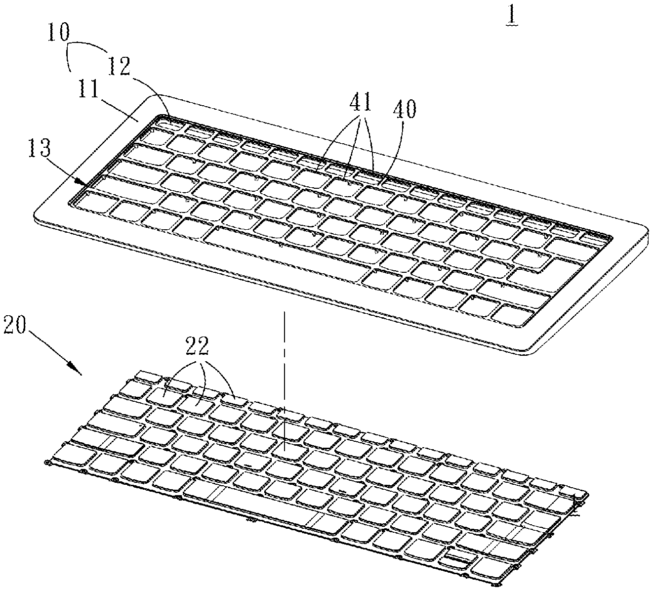
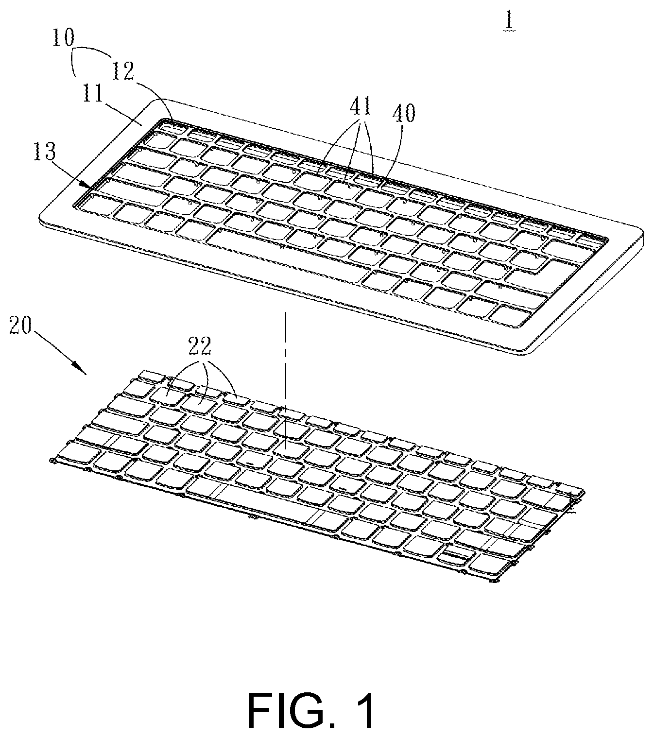
[0027] FIG. 1 and FIG. 2 are schematic diagram and cross-sectional view of an input device of one embodiment of the present disclosure. The input device 1 of this embodiment includes a housing 10, a keyboard assembly 20, and a first light source 30. The housing 10 comprises a body 11 and a plurality of sidewalls 12. The body 11 is opaque, which can be made of opaque material or can be coated with an opaque layer to a surface thereon. The plurality of side walls 12 is transparent. In one embodiment, the surface of the plurality of sidewalls 12 is coated with a translucent layer, such as a translucent layer having a color similar to the color of the body 11, maintaining consistency from the appearance for the housing 10. However, whether the surface of the plurality of sidewalls 12 needs to be coated with a translucent layer and whether the color of the translucent layer needs to be changed according to the actual situation, which is not limited by the present disclosure.
[0028] In this embodiment, the plurality of sidewalls 12 is connected to the body 11. The plurality of sidewalls 12 is disposed along the body 11 and extends downward to form an accommodating space 13. It should be noted that the plurality of sidewalls 12 and the body 11 could be integrally formed into one piece, for example, manufactured by double injection molding, or could be connected by other methods such as pasting and riveting after they have been individually molded, but the connecting methods are not limited thereto. The keyboard assembly 20 is disposed in the accommodating space 13, which means the body 11 and the plurality of sidewalls 12 is disposed along the periphery of the keyboard assembly 20. The first light source 30 is disposed below the body 11. The "below" means that the first light source 30 is lower than the body 11 in vertical height, and the present disclosure would not limit any overlapping between the first light source 30 and the body 11 in vertical projection. The first light source 30 comprises a first light emitting element 31 and a first light source circuit board 32. The first light emitting element 31 is disposed on the first light source circuit board 32. Since the plurality of sidewalls, 12 is transparent, the light emitted from the first light emitting element 31 can be emitted from the plurality of sidewalls 12, thereby lighting up the periphery of the keyboard assembly 20.
[0029] In one embodiment, the input device 1 further comprises a controller (not shown in) connected to the first light emitting element 31 for activating and deactivating the first light emitting element 31. The electronic device can also have the lighting effects of the first light emitting component 31 corresponding to the using modes of the electronic device, to facilitate the discrimination of the current mode or the electronic device. For example, when the first light emitting element 31 is turned on, that is, the light is coming out from the plurality of sidewalls 12, the electronic device is under a state of e-competition; when the first light emitting element 31 is turned off, that is, the light is not coming out from the plurality of sidewalls 12, the electronic device is under a state of sleep. In this way, the current mode or state of the electronic device can be simply discriminated according to the light emitting state of the plurality of sidewalls 12.
[0030] In one embodiment, the keyboard assembly 20 comprises a baseplate 21 and a plurality of keyswitches 22 disposed on the baseplate 21. The plurality of sidewalls 12 extends from the joint between the body 11 toward the baseplate 21. In this embodiment, the angle between the plurality of sidewalls 12 and the body 11 is an obtuse angle. In other embodiments, the angle between the plurality of sidewalls 12 and the body 11 may also be an acute angle or a right angle, which is changeable according to actual requirements, and it is not limited by the present disclosure.
[0031] In one embodiment, the input device 1 further comprises an outer frame 40 which is disposed in the accommodating space 13 and is sleeved on the keyboard assembly 20. The outer frame 40 is provided with a plurality of openings 41 adapted to the plurality of keyswitches 22. The plurality of keyswitches 22 protrudes from the plurality of openings 41. The outer frame 40 can protect and position the plurality of keyswitches 22. In addition, the height of the outer frame 40 is lower than that of the body 11. That is, a height difference exists between the outer frame 40 and the body 11, which prevents the outer frame 40 from blocking light coming out from the plurality of sidewalls 12.
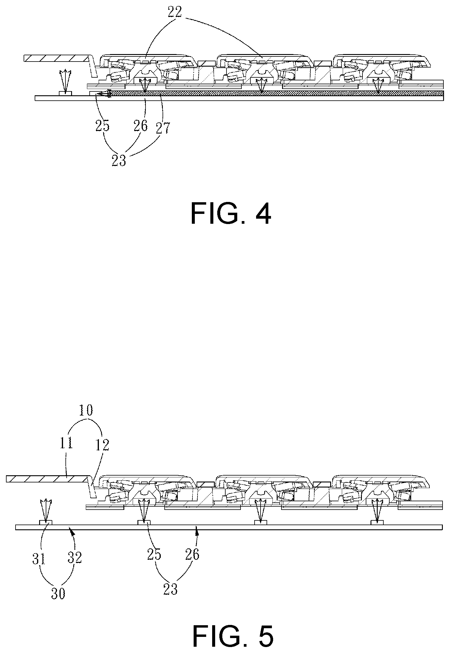
[0032] FIG. 3 and FIG. 4 are cross-sectional views of an input device of another embodiment of the present disclosure. In an embodiment, the keyboard assembly 20 further comprises a second light source 23 disposed below the baseplate 21. Holes 24 are provided at positions on the baseplate 21 respectively corresponding to the plurality of keyswitches 22. The light from the second light source 23 is emitted to the plurality of keyswitches 22 from the hole 24. It should be noted that the second light source 23 may also be disposed above the baseplate 21, which can be changed according to actual requirements, but it is not limited by the present disclosure.
[0033] In one embodiment, as shown in FIG. 3, the second light source 23 comprises a plurality of second light emitting elements 25 and a second light source circuit board 26. The number of the plurality of second light emitting elements 25 corresponds to the plurality of keyswitches 22. The lights from the plurality of second light emitting elements 25 are respectively emitted to the corresponding keyswitches 22. The plurality of second light emitting elements 25 is, for example, light emitting diodes (LEDs).
[0034] In another embodiment, the second light source 23 comprises a plurality of second light emitting elements 25, a second light source circuit board 26, and a second light guiding plate 27. The number of second light emitting elements 25 is less than the number of keyswitches 22. A plurality of second light emitting elements 25 is disposed on a side of the second light guiding plate 27. As shown in FIG. 4, this embodiment describes the light emitting state of one of the plurality of second light emitting elements 25 disposed on the side of the second light guide plate 27 in a cross-sectional view. The light from the second light emitting element 25 diffuses when passing through the second light guiding plate 27 and is emitted to the plurality of keyswitches 22. It should be noted that the second light guide plate 27 may be provided with a reflective layer and/or a light shielding layer according to the requirements to improve the luminous efficiency, but it is not limited by the present disclosure.
[0035] Referring to FIG. 3 and FIG. 5, a cross-sectional view of an input device 1 of another embodiment of the present disclosure, in one embodiment, the first light source circuit board 32 is disposed below the body 11. A gap exists between the first light source circuit board 32 and the body 11. That is, the first light source circuit board 32 is not directly connected to the body 11.
[0036] In one embodiment, the first light source circuit board 32 and the second light source circuit board 26 are individually provided. In another embodiment, the first light source circuit board 32 and the second light source circuit board 26 are integrally provided. The term "integrally" indicates that the first light source circuit board 32 and the second light source circuit board 26 could be integrally manufactured as a single element, or could be connected to form a one-piece by other methods.
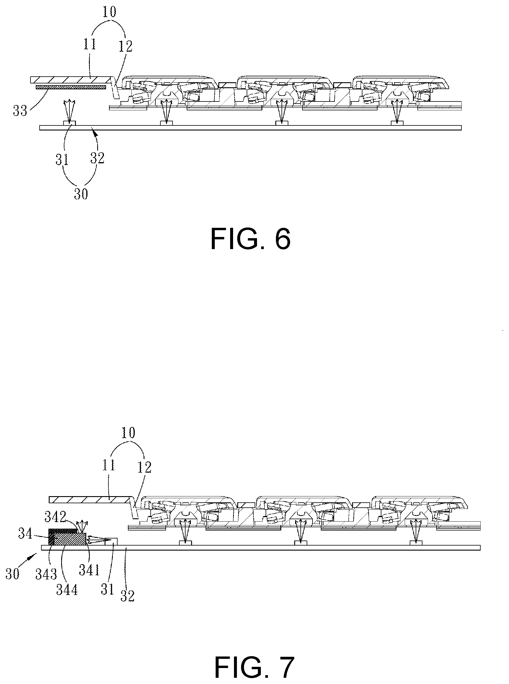
[0037] In addition, in one embodiment, the first light source 30 comprises a plurality of first light emitting elements 31, a first light source circuit board 32, and a first reflective layer 33. The plurality of first light emitting elements 31 are disposed around the body 11. The first reflective layer 33 is disposed on the optical path of the plurality of first light emitting elements 31. That is, the first reflective layer 33 is disposed on a surface of the body 11 opposite to the plurality of first light emitting elements 31, which means that each sidewall 12 is correspondingly provided with the first light emitting element 31 and the first reflective layer 33. FIG. 6 is a cross-sectional view of an input device 1 of another embodiment of the present disclosure. This embodiment describes the light emitting state when one of the plurality of first light emitting elements 31 is disposed on the first light source circuit board 32, and the first reflective layer 33 is provided on the optical path of the first light emitting element 31 in a cross sectional view. A part of the light from the first light emitting element 31 is directly emitted to the corresponding sidewall 12, and part of it is reflected by the first reflective layer 33 before being emitted to the corresponding sidewall 12. It should be noted that the first reflective layer 33 may be a single element, such as a ring frame shaped reflective layer, or maybe a plurality of reflective layers provided individually, but it is not limited by the present disclosure
[0038] FIG. 7 is a cross-sectional view of an input device 1 of another embodiment of the present disclosure. In this embodiment, the first light source 30 comprises a first light emitting element 31, a first light source circuit board 32, and a first light guiding plate 34. The first light emitting element 31 is disposed on an upper surface of the first light source circuit board 32. The first light guiding plate 34 is disposed on a side of the first light emitting element 31. The first light guide plate 34 is provided with a light incident surface 341, a light exit surface 342, a side surface 343, and a bottom surface 344. The light exit surface 342 is opposite to the bottom surface 344. The light incident surface 341 is connected to the light exit surface 342. The side surface 343 is connected to the bottom surface 344. The side surface 343 is provided with a reflective layer or a light shielding layer. In some embodiments, a part of the light exit surface 342 away from the sidewall 12 may also be provided with a reflective layer or a light shielding layer according to requirements, but it is not limited by the present disclosure.
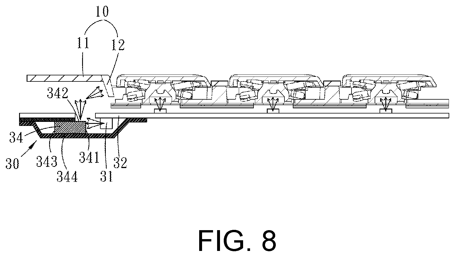
[0039] FIG. 8 is a cross-sectional view of an input device 1 of another embodiment of the present disclosure. In this embodiment, the first light source 30 comprises a first light emitting element 31, a first light source circuit board 32, and a first light guiding plate 34. The first light emitting element 31 is disposed on a lower surface of the first light source circuit board 32. The first light guiding plate 34 is disposed on a side of the first light emitting element 31. The first light guide plate 34 is provided with a light incident surface 341, a light exit surface 342, a side surface 343, and a bottom surface 344. The light exit surface 342 is opposite to the bottom surface 344. The light incident surface 341 is connected to the light exit surface 342. The side surface 343 is connected to the bottom surface 344. The side surface 343 and the bottom surface 344 are provided with a reflective layer or a light shielding layer. In some embodiments, a part of the light exit surface 342 away from the sidewall 12 may also be provided with a reflective layer or a light shielding layer according to requirements, but it is not limited by the present disclosure.
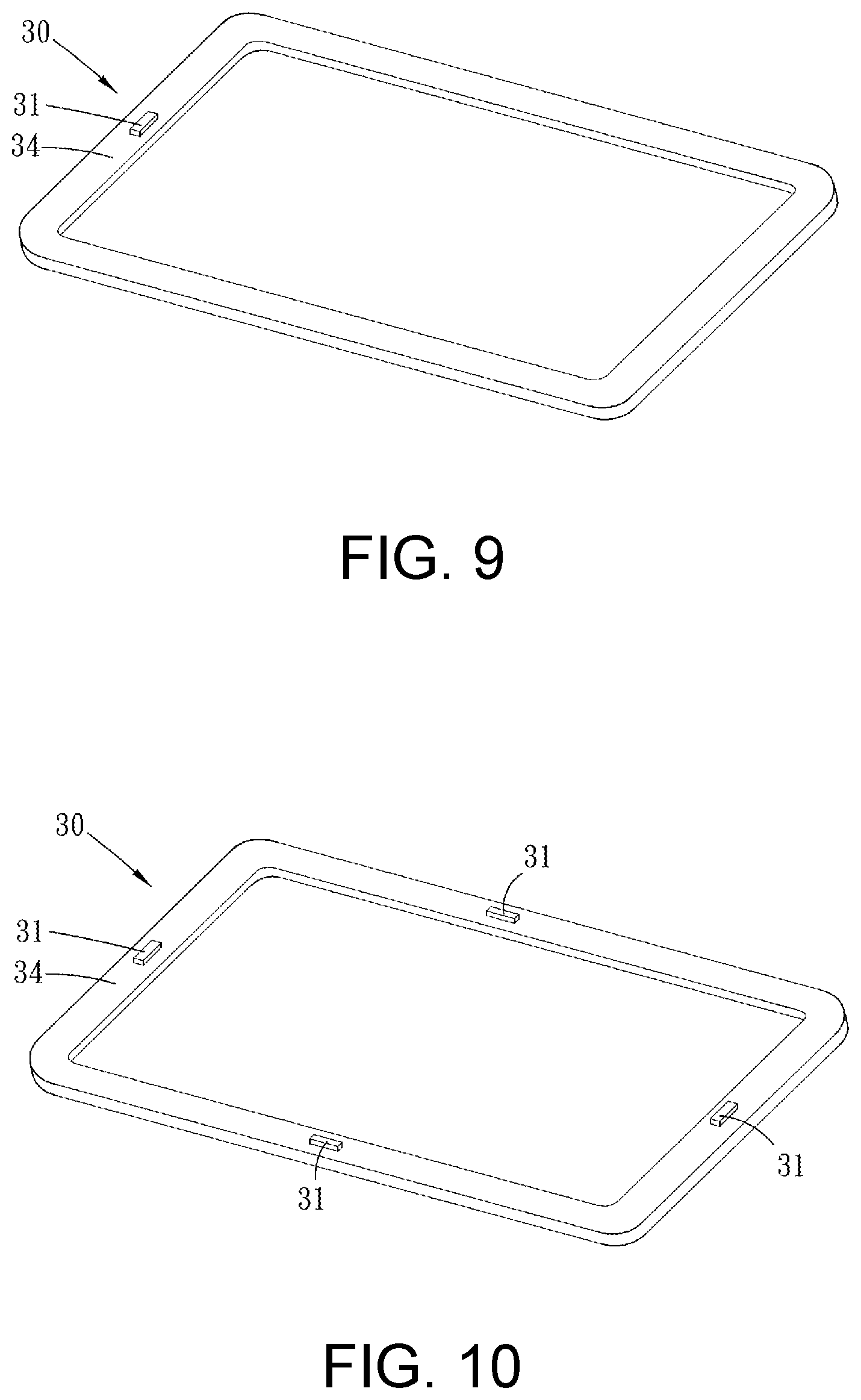
[0040] FIG. 9 is a schematic diagram of a first light source of an input device 1 of one embodiment of the present disclosure. In this embodiment, the first light source 30 comprises a first light emitting element 31, a first light source circuit board (not shown), and a first light guiding plate 34. The first light emitting element 31 is disposed on the first light guiding plate 34. The first light guiding plate 34 corresponds to each sidewall 12. That is, each sidewall 12 is correspondingly provided with a first light guiding plate 34, and the light from the first light emitting element 31 is emitted to the corresponding sidewall 12 through the first light guiding plate 34. It should be noted that the first light guiding plate 34 may be a single element, such as a ring frame light guiding plate, or maybe a plurality of light guiding plates provided individually, but it is not limited by the present disclosure.
[0041] FIG. 10 is a schematic diagram of a first light source of an input device 1 of another embodiment of the present disclosure. In this embodiment, the first light source 30 comprises a plurality of first light emitting elements 31, a first light source circuit board (not shown), and a first light guiding plate 34. The plurality of first light emitting elements 31 is disposed on the first light guiding plate 34. The first light guiding plate 34 corresponds to each sidewall 12. That is, each sidewall 12 is correspondingly provided with a first light guiding plate 34, and the light from the plurality of first light emitting elements 31 is emitted to the corresponding sidewall 12 through the first light guiding plate 34. It should be noted that the first light guiding plate 34 may be a single element, such as a ring frame light guiding plate, or maybe a plurality of light guiding plates provided individually, but it is not limited by the present disclosure. In this embodiment, the plurality of first light emitting elements 31 is circumferentially disposed on the first light guiding plate 34 including various situations, such as each sidewall 12 is correspondingly provided with one or more than one first light emitting elements 31, or the plurality of first light emitting elements 31 are only disposed on the two opposing sidewalls 12, but it is not limited by the present disclosure.
[0042] FIG. 11 and FIG. 12 are cross-sectional views of an input device of another embodiment of the present disclosure. In one embodiment, the first light source 30 is disposed below the body 11 and is connected to the body 11. That is, the first light source 30 is directly disposed on a surface of the body 11 opposite to the baseplate 21.
[0043] In one embodiment, the first light source 30 comprises a plurality of first light emitting elements 31, a first light source circuit board 32, and a first reflective layer 33. A plurality of first light emitting elements 31 is disposed around the body 11, and the first reflective layer 33 is disposed on the optical path of the plurality of first light emitting elements 31. That is, the first reflective layer 33 is disposed below the plurality of first light emitting elements 31. Each side wall 12 is correspondingly provided with a first light emitting element 31 and a first reflective layer 33. A part of the light from the plurality of first light emitting elements 31 is directly emitted to the corresponding sidewall 12, and a part of the light is emitted to the first reflective layer 33 before being reflected to the corresponding sidewall 12. It should be noted that the first reflective layer 33 may be a single element, such as a ring frame shaped reflective layer, or may be a plurality of reflective layers provided individually, but it is not limited by the present disclosure.
[0044] In one embodiment, the first light emitting element 31 may be a light emitting diode (LED) or a flexible light bar, but it is not limited by the present disclosure.
[0045] In summary, the present disclosure proposed an input device in which a glowing effect can be created on the periphery of the keyboard assembly by providing the body with the first light source emitting light which emits the plurality of the sidewalls of the housing. By configuring computer using modes, which correspond to the light emitting states, it is possible for users to intuitively discriminate the using patterns.
[0046] It is to be understood that the term "comprises", "comprising", or any other variants thereof, is intended to encompass a non-exclusive inclusion, such that a process, method, article, or device of a series of elements not only include those elements but also comprises other elements that are not explicitly listed, or elements that are inherent to such a process, method, article, or device. An element defined by the phrase "comprising a . . . " does not exclude the presence of the same element in the process, method, article, or device that comprises the element.
[0047] Although the present disclosure has been explained in relation to its preferred embodiment, it does not intend to limit the present disclosure. It will be apparent to those skilled in the art having regard to this present disclosure that other modifications of the exemplary embodiments beyond those embodiments specifically described here may be made without departing from the spirit of the disclosure. Accordingly, such modifications are considered within the scope of the disclosure as limited solely by the appended claims.
* * * * *
D00000
D00001
D00002
D00003
D00004
D00005
D00006
D00007
XML
uspto.report is an independent third-party trademark research tool that is not affiliated, endorsed, or sponsored by the United States Patent and Trademark Office (USPTO) or any other governmental organization. The information provided by uspto.report is based on publicly available data at the time of writing and is intended for informational purposes only.
While we strive to provide accurate and up-to-date information, we do not guarantee the accuracy, completeness, reliability, or suitability of the information displayed on this site. The use of this site is at your own risk. Any reliance you place on such information is therefore strictly at your own risk.
All official trademark data, including owner information, should be verified by visiting the official USPTO website at www.uspto.gov. This site is not intended to replace professional legal advice and should not be used as a substitute for consulting with a legal professional who is knowledgeable about trademark law.