Methods And Systems For Producing Light Olefins From Naphtha
VAN WILLIGENBURG; Joris
U.S. patent application number 16/767224 was filed with the patent office on 2020-12-24 for methods and systems for producing light olefins from naphtha. The applicant listed for this patent is SABIC Global Technologies B.V.. Invention is credited to Joris VAN WILLIGENBURG.
| Application Number | 20200399546 16/767224 |
| Document ID | / |
| Family ID | 1000005119127 |
| Filed Date | 2020-12-24 |

| United States Patent Application | 20200399546 |
| Kind Code | A1 |
| VAN WILLIGENBURG; Joris | December 24, 2020 |
METHODS AND SYSTEMS FOR PRODUCING LIGHT OLEFINS FROM NAPHTHA
Abstract
Methods and systems for producing olefins from a naphtha feedstock are provided. Methods can include pyrolyzing the naphtha feedstock in the presence of hydrogen gas to produce a first effluent, separating the first effluent into light components, heavy components and one or more olefin product streams, steam cracking the light components to produce a second effluent, and extracting aromatics, if any, from the heavy components to produce a third effluent.
| Inventors: | VAN WILLIGENBURG; Joris; (Maastruct, NL) | ||||||||||
| Applicant: |
|
||||||||||
|---|---|---|---|---|---|---|---|---|---|---|---|
| Family ID: | 1000005119127 | ||||||||||
| Appl. No.: | 16/767224 | ||||||||||
| Filed: | November 15, 2018 | ||||||||||
| PCT Filed: | November 15, 2018 | ||||||||||
| PCT NO: | PCT/IB2018/058997 | ||||||||||
| 371 Date: | May 27, 2020 |
Related U.S. Patent Documents
| Application Number | Filing Date | Patent Number | ||
|---|---|---|---|---|
| 62594329 | Dec 4, 2017 | |||
| Current U.S. Class: | 1/1 |
| Current CPC Class: | C10G 2400/30 20130101; C10K 3/04 20130101; C10G 47/22 20130101; C10G 2400/22 20130101; C10G 2300/1044 20130101; C10G 2400/20 20130101 |
| International Class: | C10G 47/22 20060101 C10G047/22; C10K 3/04 20060101 C10K003/04 |
Claims
1. A method for producing olefins and aromatics from a naphtha feedstock, the method comprising the steps of: (a) pyrolyzing the naphtha feedstock in the presence of hydrogen gas to produce a first effluent comprising first olefins; (b) separating the first effluent into light components, heavy components, if any, and one or more olefin product streams; (c) steam cracking the light components to produce a second effluent comprising second olefins; and (d) extracting aromatics, if any, from the heavy components to produce a third effluent.
2. The method of claim 1, wherein the first effluent comprises C.sub.2 to C.sub.4 paraffins and iso-paraffins.
3. The method of claim 1, wherein after pyrolyzing, the first effluent has a temperature of about 700.degree. C. to about 860.degree. C.
4. The method of claim 1, wherein after steam cracking, the second effluent has a temperature of about 820.degree. C. to about 880.degree. C.
5. The method of claim 1, wherein the separating the first effluent comprises compressing the first effluent to pressurize the first effluent and condense the heavy components.
6. The method of claim 5, further comprising treating the first effluent to remove carbon dioxide and water, if any.
7. The method of claim 1, further comprising combining the first effluent and the second effluent prior to the separating.
8. The method of claim 1, further comprising the steps of: (e) extracting hydrogen, if any, from the light components to produce a hydrocarbon stream and recycling the hydrogen by mixing it with the naphtha feedstock; (f) extracting methane, if any, from the hydrocarbon stream to produce a C.sub.2+ stream; (g) extracting ethylene and ethane, if any, from the C.sub.2+ stream to produce a C.sub.3+ stream; (h) extracting propylene and propane, if any, from the C.sub.3+ stream to produce a C.sub.4+ stream; (i) extracting C.sub.4 components, if any, from the C.sub.4+ stream to produce a C.sub.5+ stream; and (j) extracting benzene, toluene, xylene, ethylbenzene, C.sub.9+ aromatics and heavy oil, if any, from the heavy components and the C.sub.5+ stream to produce a third effluent.
9. The method of claim 8, further comprising recycling the third effluent by combining it with the naphtha feedstock.
10. The method of claim 8, further comprising pyrolyzing the third effluent.
11. The method of any claim 8, further comprising purifying the hydrogen by removing carbon monoxide and methane, if any.
12. The method of claim 11, wherein the carbon monoxide is converted to methane and water, wherein the water is removed to produce a hydrogen stream comprising from about 85 vol-% to about 95 vol-% hydrogen.
13. The method of claim 12, wherein the methane is removed by pressure swing adsorption to produce a purified hydrogen stream comprising greater than about 99 vol-% hydrogen.
14. The method of claim 8, further comprising recycling the hydrogen by combining it with the naphtha feedstock.
15. The method of claim 8, further comprising transferring the hydrogen to one or more hydrogenation reactors.
16. The method of claim 8, further comprising the separating the ethylene and ethane into an ethylene product stream and an ethane stream.
17. The method of claim 8, further comprising separating the propylene and propane into a propylene product stream and a propane stream.
18. The method of claim 8, further comprising steam cracking the ethane stream and the propane stream.
19. The method of claim 8, further comprising the steps of: (k) extracting C.sub.4 and lighter hydrocarbons, if any, from the heavy components and the C.sub.5+ stream to produce a C.sub.4- stream; and (l) recycling the C.sub.4- stream by combining it with the first effluent and/or the second effluent.
20. A method for producing olefins and aromatics from a naphtha feedstock, the method consisting of the steps of: (a) pyrolyzing the naphtha feedstock in the presence of hydrogen gas to produce a first effluent comprising first olefins; (b) separating the first effluent into light components and heavy components and an olefin product streams, wherein the heavy components comprise aromatics; (c) steam cracking the light components to produce a second effluent comprising second olefins; and (d) extracting aromatics from the heavy components to produce a third effluent, wherein the yield sum of the ethylene and the propylene is greater than about 51%.
Description
CROSS REFERENCE TO RELATED APPLICATIONS
[0001] This application claims the benefit of priority of U.S. Provisional Patent Application No. 62/594,329, filed Dec. 4, 2017, which is hereby incorporated by reference in its entirety.
BACKGROUND OF THE INVENTION
A. Field of the Invention
[0002] The invention generally concerns methods and systems for producing light olefins from naphtha.
B. Description of Related Art
[0003] Light olefins, such as ethylene and propylene, are important petrochemical products which can be used to produce plastics such as polyethylene, polypropylene, and various co-polymers. Light olefins can be produced from hydrocarbon feedstocks including naphtha. Naphtha can be found in petroleum distillate streams and can contain a variety of components, depending on the composition of the crude source.
[0004] Light olefins can be produced by the steam cracking of naphtha. However, steam cracking can be energy-intensive and can result in low yields of ethylene and propylene from naphtha. For example, although steam cracking of lighter paraffins can have high light olefins yield, steam cracking of naphtha containing large amounts of aromatic compounds and/or naphthenes can have low light olefins yield.
[0005] Certain methods are known in the art for converting naphtha to light olefins. For example, European Patent No. EP 0089310 discloses a method of producing olefins by steam cracking hydrocarbons under pressure and with coexistence of methane and hydrogen, including making hydrocarbons coexist with a mixed gas of methane and hydrogen in a methane/hydrogen mole ratio of 0.2 or more, performing a thermal cracking reaction, and quenching the reaction product discharge. Russian Patent No. RU 2,249,611 discloses a hydropyrolysis process using a gasoline and hydrogenated C.sub.9+ fraction feedstock. The C.sub.9+ fraction can be isolated as side-cut distillate from bottom residue obtained in fractionation of liquid pyrolysis products. European Patent Publication No. EP 0068051 discloses a hydropyrolysis process for upgrading higher molecular weight feedstock to lower molecular weight liquid products by pressurizing and heating the feedstock.
[0006] U.S. Pat. No. 3,907,920 discloses an integrated process to produce ethylene and methane including a first stage hydropyrolysis of hydrocarbon oil followed by cracking the hydropyrolysis effluent, separating and recycling the hydrogen and ethane, and recovering the ethylene and methane. U.S. Patent Publication No. 2013/0228495 discloses a system and process for producing petrochemicals, including olefins and aromatics, from crude oil feedstock by a steam pyrolysis process integrated with a hydroprocessing process. German Patent Publication No. DE 2,708,412 discloses an integrated process to produce ethylene, ethane, propane, benzene, and syngas including a hydropyrolysis process followed by an aromatic separation process, a low temperature separation process, and an ethane cracking process.
[0007] However, there remains a need for techniques of producing light olefins, e.g., ethylene and propylene, from naphtha feedstock.
SUMMARY OF THE INVENTION
[0008] The disclosed subject matter provides methods and systems for producing light olefins from naphtha. Particularly, according to the disclosed methods and systems, steam cracking and pyrolysis of naphtha can be combined to improve the yield of light olefins from naphtha.
[0009] In certain embodiments, an exemplary method of producing light olefins, e.g., ethylene and propylene, from a naphtha feedstock includes pyrolyzing the naphtha feedstock in the presence of hydrogen gas to produce a first effluent including first olefins, and separating the first effluent into light components, heavy components and one or more olefin product streams. The method further includes steam cracking the light components to produce a second effluent including second olefins, and extracting aromatics from the heavy components to produce a third effluent.
[0010] In certain embodiments, the first effluent can contain C.sub.2 to C.sub.4 paraffins and iso-paraffins. After pyrolysis, the first effluent can have a temperature from about 700.degree. C. to about 860.degree. C. After steam cracking, the second effluent can have a temperature from about 820.degree. C. to about 880.degree. C.
[0011] In certain embodiments, the first effluent can be compressed to pressurize the first effluent to condense the heavy components from the light components. The first effluent can be treated to remove carbon dioxide and water, if any. In certain embodiments, the second effluent can be combined with the first effluent prior to separating light components and heavy components.
[0012] In certain embodiments, the method can further include extracting hydrogen from the light components to produce a hydrocarbon stream and recycling the hydrogen by mixing it with the naphtha feedstock. The method can include extracting methane from the hydrocarbon stream to produce a C.sub.2+ stream, extracting ethylene and ethane from the C.sub.2+ stream to produce a C.sub.3+ stream, extracting propylene and propane from the C.sub.3+ stream to produce a C.sub.4+ stream, extracting C.sub.4 components from the C.sub.4+ stream to produce a C.sub.5+ stream, and extracting benzene, toluene, xylene, ethylbenzene, C.sub.9+ aromatics, and heavy oil from the heavy components and the C.sub.5+ stream to produce a third effluent. The method can further include recycling the third effluent by combining it with the naphtha feedstock. In certain embodiments, the method can include pyrolyzing the third effluent.
[0013] In certain embodiments, the hydrogen can be purified by removing carbon monoxide and methane. For example, the carbon monoxide can be converted to methane and water. The water can be removed to produce a hydrogen stream containing from about 85 vol-% to about 95 vol-% hydrogen. The methane can be removed by pressure swing adsorption to produce a purified hydrogen stream comprising greater than about 99 vol-% hydrogen. The hydrogen can be recycled by combining it with the naphtha feedstock. Alternatively or additionally, the hydrogen can be transferred to one or more hydrogenation reactors.
[0014] In certain embodiments, the ethylene and ethane can be separated into an ethylene product stream and an ethane stream and the propylene and propane can be separated into a propylene product stream and a propane stream. The method can include steam cracking the ethane stream and the propane stream. In certain embodiments, the method can include extracting C.sub.4 and lighter hydrocarbons from the heavy components and the C.sub.5+ stream to produce a C.sub.4- stream, and recycling the C.sub.4- stream by combining it with the first effluent and/or the second effluent. In accordance with the disclosed method, the combined yield of ethylene and propylene can be greater than about 51%.
[0015] The presently disclosed subject matter also provides systems for producing light olefins from naphtha. In certain embodiments, an exemplary system includes a pyrolysis unit to pyrolyze the naphtha feedstock in the presence of hydrogen. The system also includes a separation system, coupled to the pyrolysis unit, to separate heavy components, light components and olefin products. A steam cracking unit, coupled to the separation system, is provided to crack the light components and produce olefins. The system can also include an aromatics extraction unit, coupled to the separation system, to produce aromatics and recycle paraffins and/or naphthenes from the heavy components.
[0016] In certain embodiments, the system can further include a gas compression and treatment unit, coupled to the pyrolysis unit, to separate heavy components and remove carbon dioxide and water. The separation system can include a hydrogen separator, a demethanizer, a deethanizer, a depropanizer, and/or a debutanizer. The system can include a carbon monoxide conversion unit, coupled to the hydrogen separator, for converting carbon monoxide to a hydrogen stream comprising hydrogen, methane, and water. The system can further include a dryer, coupled to the carbon monoxide conversion unit, for removing water from the hydrogen stream and a pressure swing adsorption unit, coupled to the carbon monoxide conversion unit, for separating methane from the hydrogen.
[0017] In certain embodiments, the system can include a C.sub.2 splitter, coupled to the deethanizer, for separating a ethane stream and an ethylene product stream, a C.sub.3 splitter, coupled to the depropanizer, for separating a propane stream and an propylene product stream, and a recycle line, coupled to the C.sub.2 splitter and the C.sub.3 splitter, for transferring the ethane stream and the propane stream to the steam cracking unit.
[0018] As used herein, the term "about" or "approximately" means within an acceptable error range for the particular value as determined by one of ordinary skill in the art, which will depend in part on how the value is measured or determined, i.e., the limitations of the measurement system. For example, "about" can mean a range of up to 20%, up to 10%, up to 5%, and or up to 1% of a given value.
[0019] As used herein, the term "primarily" means greater than 50%, e.g., 50.1% or greater, 50.1 to 99.9%, or preferably 51% to 99%, or any range therebetween.
[0020] In the context of the present invention, twenty embodiments are now described. Embodiment 1 relates to method for producing olefins and aromatics from a naphtha feedstock. The method includes the steps of (a) pyrolyzing the naphtha feedstock in the presence of hydrogen gas to produce a first effluent containing first olefins; (b) separating the first effluent into light components, heavy components, if any, and one or more olefin product streams; (c) steam cracking the light components to produce a second effluent containing second olefins; and (d) extracting aromatics, if any, from the heavy components to produce a third effluent. Embodiment 2 is the method of embodiment 1, wherein the first effluent contains C.sub.2 to C.sub.4 paraffins and iso-paraffins. Embodiment 3 is the method of any of embodiments 1 or 2, wherein after pyrolyzing, the first effluent has a temperature of about 700.degree. C. to about 860.degree. C. Embodiment 4 is the method of any of embodiments 1 to 3, wherein after steam cracking, the second effluent has a temperature of about 820.degree. C. to about 880.degree. C. Embodiment 5 is the method of embodiments 1 one to 4, wherein the separating the first effluent includes compressing the first effluent to pressurize the first effluent and condense the heavy components. Embodiment 6 is the method of embodiment 5, further including the step of treating the first effluent to remove carbon dioxide and water, if any. Embodiment 7 is the method of embodiments 1 to 6, further including the step of combining the first effluent and the second effluent prior to the separating. Embodiment 8 is the method of any of embodiments 1 to 7, further including the steps of (e) extracting hydrogen, if any, from the light components to produce a hydrocarbon stream and recycling the hydrogen by mixing it with the naphtha feedstock; (f) extracting methane, if any, from the hydrocarbon stream to produce a C2+ stream; (g) extracting ethylene and ethane, if any, from the C2+ stream to produce a C3+ stream; (h) extracting propylene and propane, if any, from the C3+ stream to produce a C4+ stream; (i) extracting C4 components, if any, from the C4+ stream to produce a C5+ stream; and (j) extracting benzene, toluene, xylene, ethylbenzene, C9+ aromatics and heavy oil, if any, from the heavy components and the C5+ stream to produce a third effluent. Embodiment 9 is the method of embodiment 8, further comprising recycling the third effluent by combining it with the naphtha feedstock. Embodiment 10 is the method of any of embodiments 8 or 9, further including the step of pyrolyzing the third effluent. Embodiment 11 is the method of any one of embodiments 8 to 10, further including the step of purifying the hydrogen by removing carbon monoxide and methane, if any. Embodiment 12 is the method of embodiment 11, wherein the carbon monoxide is converted to methane and water, wherein the water is removed to produce a hydrogen stream containing from about 85 vol-% to about 95 vol-% hydrogen. Embodiment 13 is the method of embodiment 12, wherein the methane is removed by pressure swing adsorption to produce a purified hydrogen stream comprising greater than about 99 vol-% hydrogen. Embodiment 14 is the method of any one of embodiments 8 to 13, further including the step of recycling the hydrogen by combining it with the naphtha feedstock. Embodiment 15 is the method of any one of embodiments 8 to 14, further comprising transferring the hydrogen to one or more hydrogenation reactors. Embodiment 16 is the method of any one of embodiments 8 to 15, further including the step of separating the ethylene and ethane into an ethylene product stream and an ethane stream. Embodiment 17 is the method of any one of embodiments 8 to 16, further including the step of separating the propylene and propane into a propylene product stream and a propane stream. Embodiment 18 is the method of any one of embodiments 8 to 17, further including steam cracking the ethane stream and the propane stream. Embodiment 19 is the method of any one of embodiments 8 to 18, further including the steps of: (k) extracting C4 and lighter hydrocarbons, if any, from the heavy components and the C5+ stream to produce a C.sub.4- stream; and (l) recycling the C4- stream by combining it with the first effluent and/or the second effluent. Embodiment 20 is the method of any of embodiments 1 to 19, wherein the yield sum of the ethylene and the propylene is greater than about 51%.
BRIEF DESCRIPTION OF THE DRAWINGS
[0021] Advantages of the present invention may become apparent to those skilled in the art with the benefit of the following detailed description and upon reference to the accompanying drawings.
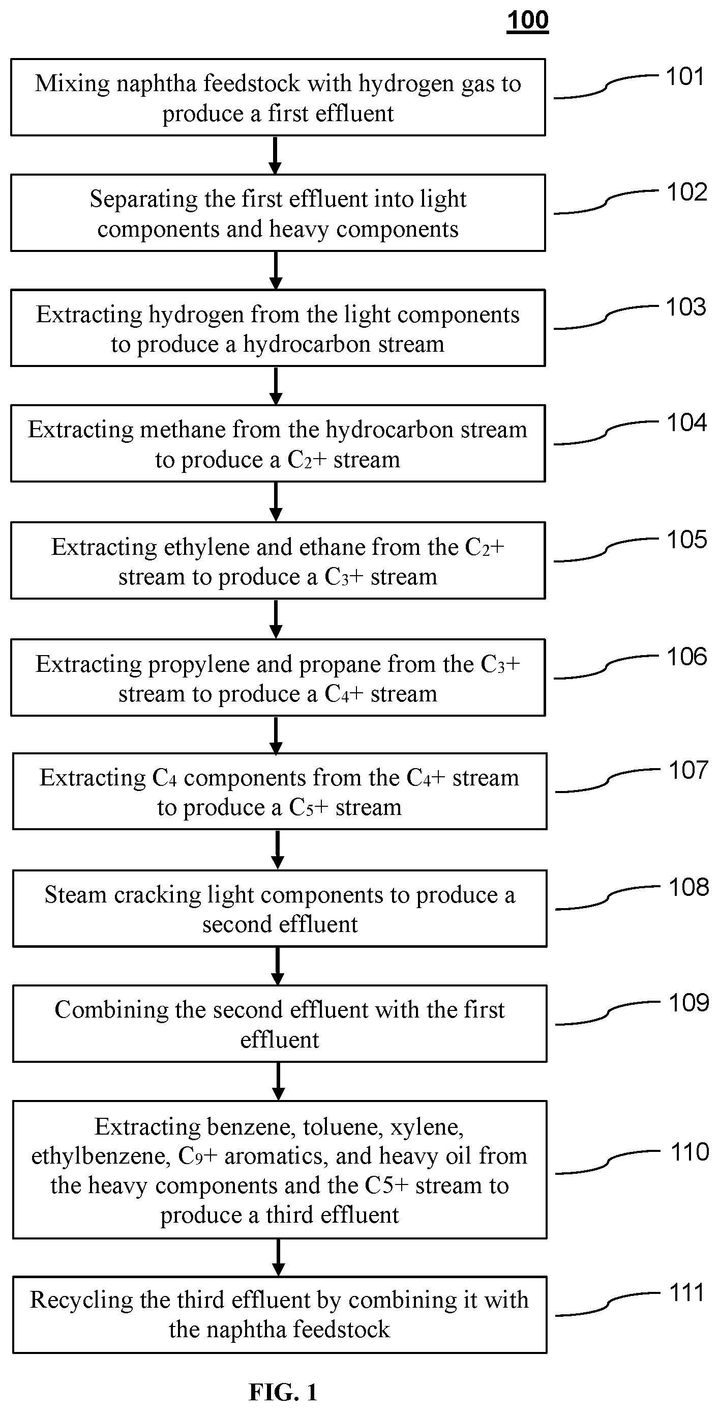
[0022] FIG. 1 depicts a method of producing light olefins from naphtha according to one exemplary embodiment of the disclosed subject matter.
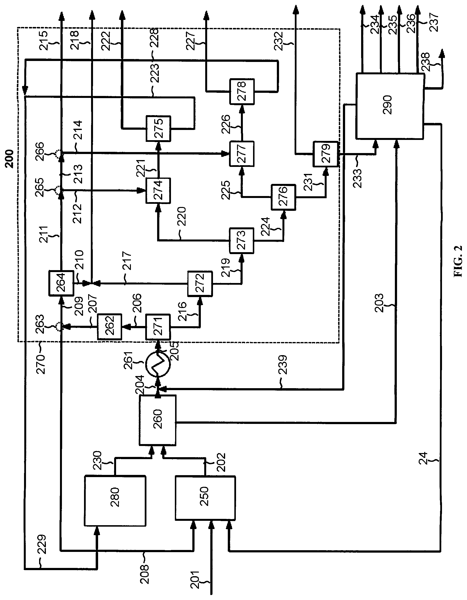
[0023] FIG. 2 depicts a system for producing light olefins from naphtha according to one exemplary embodiment of the disclosed subject matter.
[0024] While the invention is susceptible to various modifications and alternative forms, specific embodiments thereof are shown by way of example in the drawings. The drawings may not be to scale.
DETAILED DESCRIPTION
[0025] The presently disclosed subject matter provides methods and systems for producing light olefins from a hydrocarbon feedstock, particularly, by combining steam cracking and pyrolysis to improve the yield of ethylene and/or propylene from naphtha. Heavier hydrocarbons, e.g., paraffins and naphthenes, can be recycled to a pyrolysis unit, which has a higher yield of olefins from such heavier molecules than steam cracking. Lighter hydrocarbons, e.g., ethane and propane, can be recycled to a steam cracking unit, which has a higher yield of olefins from such lighter molecules than hydropyrolyis.
[0026] The disclosed subject matter provides methods of producing light olefins, e.g., ethylene and/or propylene, from naphtha feedstock. In certain embodiments, the method can include mixing naphtha feedstock with hydrogen gas to produce a first effluent, separating the first effluent into light components, heavy components and one or more olefin product streams, steam cracking the light components to produce a second effluent, and extracting aromatics, if any, from the heavy components to produce a third effluent.
[0027] For the purpose of illustration and not limitation, FIG. 1 is a schematic representation of a method according to a non-limiting embodiment of the disclosed subject matter. In certain embodiments, the method 100 can include mixing naphtha feedstock with hydrogen gas to produce a first effluent 101. The naphtha feedstock of the presently disclosed subject matter can originate from various sources, e.g., natural gas condensates, petroleum distillates, coal tar distillates and/or peat. For example, the naphtha feedstock can include light naphtha, heavy naphtha, straight run naphtha, full range naphtha, delayed coker naphtha, fluid catalytic cracking (FCC) naphtha, naphtha produced from syngas (i.e., a stream including carbon monoxide and hydrogen) via Fischer-Tropsch synthesis, coker fuel oil and/or gas oils, e.g., light coker gas oil and heavy coker gas oil.
[0028] The naphtha feedstock can be a hydrocarbon stream that is rich in paraffins, iso-paraffins, and/or naphthenes. For example, the naphtha feedstock can contain from about 0 wt-% to about 100 wt-% paraffins and/or from about 0 wt-% to about 100 wt-% iso-paraffins. The naphtha feedstock can further include aromatics and/or C.sub.4 and higher olefins. For example, the naphtha feedstock can contain less than about 30 wt-% aromatics and/or less than about 30 wt-% C.sub.4 and higher olefins. The naphtha feedstock can further include other components, such as diolefins, traces of polyaromatics, and asphaltenes. In certain embodiments, the naphtha feedstock can be combined with one or more recycle streams.
[0029] The naphtha feedstock can be mixed with hydrogen gas in a hydrogen stream. In certain embodiments, the method can include recycling hydrogen gas from a separation system. However, the hydrogen gas of the presently disclosed subject matter can originate from various other sources, including gaseous streams from other chemical processes, e.g., ethane cracking, methanol synthesis, the steam reforming of natural gas, natural gas liquids, or light petroleum fractions, the gasification of coal, tar, residue from a crude vacuum tower, or petroleum coke, the conversion of C.sub.4 hydrocarbons to aromatics, as a byproduct from the dehydrogenation of propane to propylene, or as a byproduct from the dehydrogenation of butane to produce 1-butene or isobutylene.
[0030] In certain embodiments, the hydrogen gas can be part of a purified hydrogen stream. For example, the amount of hydrogen in the hydrogen stream can be greater than about 50 vol-%, greater than about 70 vol-%, greater than about 80 vol-%, greater than about 85 vol-%, greater than about 90 vol-%, greater than about 95 vol-% or greater than about 99 vol-%. In certain other embodiments, the hydrogen stream can include steam and/or methane (CH.sub.4). For example, the hydrogen stream can include from about 30 wt-% to about 90 wt-% steam and/or from about 30 wt-% to about 90 wt-% methane.
[0031] In certain embodiments, the method includes pyrolyzing the naphtha feedstock in the presence of hydrogen to form a first effluent, e.g., via a pyrolysis reaction in a pyrolysis unit. The pyrolysis reaction can be performed at temperatures ranging from about 700.degree. C. to about 860.degree. C., i.e., at the exit of the pyrolysis unit. The pyrolysis reaction can be performed at pressures ranging from about 0.5 bar (absolute) to about 40 bar (absolute), i.e., at the exit of the pyrolysis unit. The naphtha feedstock can have a residence time in the pyrolysis unit from about 10 ms to about 800 ms. In certain embodiments, it can be advantageous for the pyrolysis reaction to favor ethane, propane, ethylene and/or propylene. For example, with respect to the sum total of ethane, propane, ethylene and propylene, the pyrolysis reaction can have selectivity of greater than about 50%, greater than about 55%, greater than about 60%, greater than about 65%, or greater than about 70%.
[0032] In certain embodiments, the first effluent can include paraffins, iso-paraffins, olefins, diolefins, acetylenes, aromatics, naphthenes, hydrogen, methane, carbon dioxide (CO.sub.2), and/or carbon monoxide (CO). For example, the first effluent can include C.sub.2 to C.sub.4 paraffins and iso-paraffins. In certain embodiments, the first effluent can contain from about 15 wt-% to about 50 wt-% paraffins and/or from about 20 wt-% to about 50 wt-% olefins and/or from about 2 wt-% to about 15 wt-% diolefins and/or from about 2 wt-% to about 20 wt-% aromatics. In certain embodiments, the first effluent can further include components recycled by combination with other streams. For example, the first effluent can include from about 10 wt-% to about 50 wt-% methane and/or from about 1 wt-% to about 10 wt-% hydrogen.
[0033] In certain embodiments, the method 100 further includes separating the first effluent into light components and heavy components 102. For example, the method can include compressing the first effluent and condensing heavy components, e.g., C.sub.5 and higher olefins, paraffins, aromatics, and naphthenes. For example, the heavy components can include 2-methyl-butane, 2,2-dimethylbutane, n-pentane, n-heptane, n-octane, n-nonane, 1-hexene, 1-heptene, 1-octyne, cyclopentane, methylcyclopentane, cyclohexane, 1,1-dimethylcyclohexane, ethylcyclohexane, benzene, toluene, mixed xylene, styrene, 1-methylindene, 1-methylnaphthalene, and/or pyrene. Compressing the first effluent can also aid in downstream separation.
[0034] In certain embodiments, the method can include treating the first effluent to remove carbon dioxide (CO.sub.2). In certain embodiments, hydrogen sulfide (H.sub.2S) is also removed by treating the first effluent. For example, CO.sub.2 and/or H.sub.2S can be removed by an acid-gas removal process, e.g., including a caustic wash and/or regenerative solvent (MEA) scrubbing. The method can further include drying the first effluent to remove water, e.g., by chilling, adsorption, and/or absorption.
[0035] In certain embodiments, the light components from the first effluent can be cooled and condensed, e.g., in a cold box. For example, the light components can be cooled to temperatures ranging from about -180.degree. C. to about -100.degree. C., from about -170.degree. C. to about -120.degree. C., or from about -160.degree. C. to about -140.degree. C. The light components can be combined with a recycle stream, e.g., from an aromatics extraction unit, prior to cooling.
[0036] In certain embodiments, the method 100 can further include extracting hydrogen and other materials from the light components to produce a hydrocarbon stream 103. For example, during cooling, hydrogen and other materials, e.g., carbon monoxide and methane, will not condense, and can be removed in gaseous form. This uncondensed gas can contain greater than about 50 mol-%, greater than about 70 mol-%, or greater than about 80 mol-% hydrogen. The amount of hydrogen in the uncondensed gas can depend on the residence time in the pyrolysis unit, the temperature of the first effluent when it exits the pyrolysis unit, and the amount of methane and/or hydrogen dilution. In certain embodiments, the uncondensed gas can contain from about 50 mol-% to about 90 mol-% hydrogen. The uncondensed gas can contain less than about 60 mol-% methane and less than about 10 mol-% carbon dioxide.
[0037] In certain embodiments, the method can include purifying hydrogen in the uncondensed gas. For example, carbon monoxide in the uncondensed gas can be converted to methane and water, e.g, by methanation, to form a stream including hydrogen, water, and methane. The water can be removed by drying the stream. In certain embodiments, after drying, the stream can contain from about 85 vol-% to about 95 vol-% hydrogen. The methane can be separated from the hydrogen by pressure swing adsorption to produce a purified hydrogen stream. In certain embodiments, the methane can be used as fuel gas, e.g., in a fuel gas grid. In certain embodiments, the purified hydrogen stream can contain greater than about 99 vol-% hydrogen.
[0038] In certain embodiments, the hydrogen can be transferred to one or more chemical processes. For example, a stream containing hydrogen can be split one or more times, and transferred to one or more reactors, e.g., one or more pyrolysis and/or hydrogenation reactors. In certain embodiments, the method includes recycling hydrogen by mixing it with the naphtha feedstock such that the hydrogen is used for the pyrolysis of the naphtha feedstock. In certain embodiments, only a portion of the hydrogen is recycled by mixing it with the naphtha feedstock. Alternatively or additionally, all or a portion of the hydrogen can be used for the hydrogenation of C.sub.2, C.sub.3, and/or aromatic hydrocarbons. Alternatively or additionally, all or a portion of the hydrogen can be used as fuel, e.g., in a pyrolysis furnace.
[0039] In certain embodiments, the method 100 further includes extracting methane from the hydrocarbon stream to produce a C.sub.2+ stream 104. For example, the methane can be extracted by distillation, e.g., in a demethanizer. In certain embodiments, the methane can be combined with the methane from the uncondensed gas. The methane can be used as fuel gas, e.g., in a fuel gas grid.
[0040] The C.sub.2+ stream can include C.sub.2 and higher hydrocarbons, for example ethane, ethylene, acetylene, propane, propylene, methylacetylene, propadiene, butadiene, 1-butene, isobutylene, n-butane, isobutane, 2-butene, vinyl-acetylene, and higher hydrocarbons such as pentane, C.sub.5 olefins, C.sub.5 diolefins, benzene, C.sub.6 olefins, C.sub.6 diolefins, cyclohexane, and cyclopentane.
[0041] In certain embodiments, the method 100 further includes extracting ethylene and ethane from the C.sub.2+ stream to produce a C.sub.3+ stream 105. For example, a C.sub.2 fraction including ethylene and ethane can be extracted by distillation, e.g., in a deethanizer. The C.sub.2 fraction can also include acetylene. In certain embodiments, the C.sub.2 fraction can be selectively hydrogenated, e.g., in a hydrogenation reactor, to convert acetylene in the C.sub.2 fraction into ethylene. After hydrogenation, the C.sub.2 fraction can contain from about 60 wt-% to about 90 wt-% ethylene and from about 10 wt-% to about 40 wt-% ethane.
[0042] The C.sub.2 fraction can be further separated, e.g., by distillation, to produce an ethylene product stream and an ethane stream. In certain embodiments, the amount of ethylene in the ethylene product stream can be greater than about 70 wt-%, greater than about 80 wt-%, greater than about 90 wt-%, greater than about 95 wt-%, or greater than about 99 wt-%. For example, the ethylene product stream can be polymer grade ethylene, i.e., contain less than 500 ppm ethane.
[0043] The C.sub.3+ stream can include C.sub.3 and higher hydrocarbons, for example propane, propylene, methylacetylene, propadiene, butadiene, 1-butene, 2-butene, vinyl-acetylene, isobutylene, n-butane, isobutane, and higher hydrocarbons such as pentane, C.sub.5 olefins, C.sub.5 diolefins, benzene, C.sub.6 olefins, C.sub.6 diolefins, cyclohexane, and cyclopentane.
[0044] In certain embodiments, the method 100 further includes extracting propylene and propane from the C.sub.3+ stream to produce a C.sub.4+ stream 106. For example, a C.sub.3 fraction including propylene and propane can be extracted by distillation, e.g., in a depropanizer. The C.sub.3 fraction can also include methylacetylene and/or propadiene. In certain embodiments, the C.sub.3 fraction can be selectively hydrogenated, e.g., in a hydrogenation reactor, to convert methylacetylene and/or propadiene in the C.sub.3 fraction into propylene. After hydrogenation, the C.sub.3 fraction can contain from about 75 wt-% to about 97 wt-% propylene and from about 3 wt-% to about 20 wt-% propane.
[0045] The C.sub.3 fraction can be further separated, e.g., by distillation, to produce a propylene product stream and a propane stream. In certain embodiments, the amount of propylene in the propylene product stream can be greater than about 70 wt-%, greater than about 80 wt-%, greater than about 90 wt-%, greater than about 95 wt-%, or greater than about 99 wt-%. For example, the propylene product stream can be refinery grade ethylene, i.e., contain greater than about 70 wt-% propylene. The propylene product stream can be chemical grade, i.e., contain greater than about 95 wt-% propylene. The propylene product stream can be polymer grade, i.e., contain from about 98 wt-% to about 99.5 wt-% propylene.
[0046] The C.sub.4+ stream can include C.sub.4 and higher hydrocarbons, for example butadiene, 1-butene, 2-butene, vinyl-acetylene, isobutylene, n-butane, isobutane, and higher hydrocarbons such as pentane, C.sub.5 olefins, C.sub.5 diolefins, benzene, C.sub.6 olefins, C.sub.6 diolefins, cyclohexane, and cyclopentane. In certain embodiments, the method 100 further includes extracting C.sub.4 components from the C.sub.4+ stream to produce a C.sub.5+ stream 107. For example, a C.sub.4 fraction including butadiene, 1-butene, isobutylene, n-butane, and isobutane can be extracted by distillation, e.g., in a debutanizer. The C.sub.5+ stream can include C.sub.5 and higher hydrocarbons. For example, the C.sub.5+ stream can include 2-methylbutane, n-pentane, 1-hexene, 1-heptene, cyclopentane, methylcyclopentane, cyclohexane, methylcyclohexane, 1,1-dimethylcyclohexane, ethylcyclohexane, and/or benzene.
[0047] In certain embodiments, the method 100 further includes steam cracking light components, e.g., ethane, propane, and/or butane, to produce a second effluent 108. The ethane can be recycled from the C.sub.2 fraction and the propane can be recycled from the C.sub.3 fraction. The ethane and propane can be combined prior to transfer to a steam cracking unit. Steam cracking can be performed at temperatures ranging from about 820.degree. C. to about 880.degree. C. and pressures ranging from about 1.4 bar (absolute) to about 3.5 bar (absolute), i.e., at the exit of the steam cracking unit. The light components can have a residence time in the steam cracking unit from about 50 ms to about 500 ms.
[0048] The second effluent can include olefins, e.g., ethylene and propylene. In certain embodiments, the amount of ethylene in the second effluent can be from about 10 wt-% to about 70 wt-%, from about 20 wt-% to about 60 wt-%, or from about 30 wt-% to about 50 wt-%. The amount of propylene in the second effluent can be from about 0.1 wt-% to about 20 wt-%, or from about 1 wt-% to about 15 wt-%. The second effluent can further include other components, for example hydrogen, methane, paraffins, aromatics and/or heavy oil.
[0049] In certain embodiments, the method 100 further includes combining the second effluent with the first effluent from the pyrolysis reaction 109. The second effluent can be combined with the first effluent before the first effluent undergoes the separations discussed above. Therefore, in certain embodiments, the second effluent can undergo compression, washing, drying, and cooling as described above. Hydrogen, methane, ethylene and ethane, propylene and propane, and C.sub.4 components can be extracted from the second effluent as described in the methods above. The second effluent can be separated into a hydrogen stream, ethylene product stream, ethane stream, propylene product stream, propane stream, C.sub.4 fraction, and C.sub.5+ stream as described above.
[0050] In certain embodiments, the method 100 further includes extracting benzene, toluene, xylene, ethylbenzene, C.sub.9+ aromatics and heavy oil from the heavy components, e.g., the condensed hydrocarbons from the compressor, and the C.sub.5+ stream to produce a third effluent 110. The method can include the selective hydrogenation of olefins and diolefins prior to extracting aromatics and heavy oil from the heavy components and the C.sub.5+ stream.
[0051] Extracting benzene, toluene, xylene, ethylbenzene, C.sub.9+ aromatics and heavy oil from the heavy components and the C.sub.5+ stream can be performed using any suitable method known in the art. For example, the extraction can use the Edeleanu process (i.e., using sulfur dioxide), the UDEX process (i.e., using diethylene glycol and other solvents), a sulfolane process, the Lurgi Arosolvan process (i.e., using 1-methyl-2-pyrrolidone), and/or the IFP process or another morphylane process (i.e, using n-formylmorpoline).
[0052] In certain embodiments, a C.sub.4- stream containing C.sub.4 and lighter hydrocarbons can be separated from the heavy components and C.sub.5+ stream. The C.sub.4- stream can be recycled by combining it with the first effluent and/or second effluent. For example, the C.sub.4- stream can be combined with the combined first and second effluents prior to cooling the first and second effluents. In certain embodiments, the C.sub.4- stream can be dried, i.e., to remove water, before it is recycled.
[0053] In certain embodiments, a heavy oil stream containing C.sub.12 and higher hydrocarbons can be separated from the heavy components and C.sub.5+ stream. The heavy components and the C.sub.5+ stream can be further separated into a benzene product stream, toluene product stream, xylene and ethylbenzene product stream, C.sub.9+ aromatics product stream, and third effluent.
[0054] The third effluent can contain primarily C.sub.5+ hydrocarbons, and can include aliphatic hydrocarbons, e.g., paraffins and isoparaffins, and naphthenes. In certain embodiments, the third effluent contains from about 50 wt-% to about 90 wt-% paraffins and/or from about 10 wt-% to about 40 wt-% naphthenes. In certain embodiments, the method 100 further includes recycling the third effluent by combining it with the naphtha feedstock 111. That is, the third effluent can be recycled to the pyrolysis reaction. In other certain embodiments, the third effluent can undergo a pyrolysis reaction in a separate pyrolysis unit.
[0055] According to methods of the presently disclosed subject matter, the combined yield of ethylene and propylene can be higher than the combined yield of ethylene and propylene from the steam cracking of naphtha without a pyrolysis reaction. For example, the combined yield of ethylene and propylene can be greater than about 40%, greater than about 50%, greater than about 60%, or greater than about 70%.
[0056] The presently disclosed subject matter further provides systems for producing light olefins, e.g., ethylene and propylene, from naphtha feedstock. For the purpose of illustration and not limitation, FIG. 2 is a schematic representation of a system according to a non-limiting embodiment of the disclosed subject matter. The system can include a pyrolysis unit 250 for pyrolyzing naphtha feedstock and an olefins and a separation system 270, coupled to the pyrolysis unit, for separating heavy components, light components, and olefin products. The system can further include a steam cracking unit 280, coupled to the separation system, for cracking the light components to produce olefins and an aromatics extraction unit 290, coupled to the separation system, to produce aromatics.
[0057] In certain embodiments, the system 200 can include a pyrolysis unit 250 for pyrolyzing naphtha feedstock in the presence of hydrogen. The pyrolysis unit can include a reactor. The reactor for use in the presently disclosed system can be a tubular reactor.
[0058] The pyrolysis unit can be coupled to a reactor feed expander and/or reactor effluent expander. For example, an expander can increase the volume of the feed and/or effluent to reduce temperature and pressure. The expander can be mechanically coupled to a compressor, where the mechanical work produced by expansion of feed and/or effluent can be used to drive the compressor, thereby efficiently recovering heat to drive other equipment. Alternatively, the reactor feed expander and/or reactor effluent expander can be coupled to a generator to produce electricity.
[0059] "Coupled" as used herein refers to the connection of a system component to another system component by any suitable means known in the art. The type of coupling used to connect two or more system components can depend on the scale and operability of the system. For example, and not by way of limitation, coupling of two or more components of a system can include one or more joints, valves, transfer lines, or sealing elements. Non-limiting examples of transfer lines include pipes, hose, tubing, and ducting, which can be made of any suitable material, including stainless steel, carbon steel, cast iron, ductile iron, non-ferrous metals and alloys, for example including aluminum, copper, and/or nickel, and non-metallic materials, e.g., concrete and plastic. Non-limiting examples of joints include threaded joints, soldered joints, welded joints, compression joints and mechanical joints. Non-limiting examples of fittings include coupling fittings, reducing coupling fittings, union fittings, tee fittings, cross fittings and flange fittings. Non-limiting examples of valves include gate valves, globe valves, ball valves, butterfly valves and check valves.
[0060] The pyrolysis unit 250 can be coupled to one or more feed lines 201, 209 for transferring naphtha feedstock and hydrogen to the pyrolysis unit. In certain embodiments, a recycle line 240 can also be coupled to the pyrolysis unit for transferring a recycle stream containing paraffins and/or naphthenes from the aromatics extraction unit 290.
[0061] In certain embodiments, the system 200 includes a gas compression and treatment unit 260 coupled to the pyrolysis unit 250, e.g., via one or more transfer lines 202. The transfer line containing the first effluent 202 can be combined with a second transfer line containing the second effluent 230 from the steam cracking unit 280. The gas compression and treatment unit can contain one or more compressors. In certain embodiments, the one or more compressors can be mechanically coupled to a reactor feed expander and/or reactor effluent expander. Additionally or alternatively, the one or more compressors can be coupled to a motor. The gas compression and treatment unit can include a scrubber for removing carbon dioxide from the first and/or second effluents. The gas compression and treatment unit can also include a dryer for removing water from the first and/or second effluents. For example, the dryer can include molecular sieves for adsorbing water.
[0062] In certain embodiments, a transfer line 203 can be coupled to the gas compression and treatment unit 260 for transferring condensed hydrocarbons from the gas compression and treatment unit to the aromatics extraction unit 290. A second transfer line 204 can be coupled to the gas compression and treatment unit for transferring uncondensed hydrocarbons to a cold box 261. In certain embodiments, the second transfer line 204 can be coupled to a recycle line 239 from the aromatics extraction unit 290.
[0063] The cold box of the presently disclosed subject matter can include one or more heat exchangers, e.g., plate fin heat exchangers, shell and tube heat exchangers, plate heat exchangers, and/or plate and shell heat exchangers, one or more coolers, one or more expanders, one or more separators, e.g., distillation columns, and/or one or more drums, e.g., knock-out drums and/or two-phase injection drums. The cold box can be made of any suitable material, for example brazed aluminum and/or stainless steel. In certain embodiments, the cold box is a brazed aluminum plate-fin heat exchanger.
[0064] The system 200 can further include a separation system 270 coupled to the cold box 261, e.g., via one or more transfer lines 205. In certain embodiments, the separation system can include a refrigeration system, which can be integrated with an absorption chiller and/or adsorption chiller. The separation system can include a hydrogen separator 271 and one or more distillation columns, e.g., a demethanizer 272, a deethanizer 273, a depropanizer 276, and/or a debutanizer 279. The distillation columns for use in the separation system can be any type known in the art to be suitable for fractional distillation. The one or more distillation columns can be adapted to continuous or batch distillation. The one or more distillation columns can be coupled to one or more condensers and one or more reboilers. The one or more distillation columns can be stage or packed columns, and can include plates, trays and/or packing material. The one or more distillation columns can be coupled to one or more transfer lines.
[0065] In certain embodiments, the separation system 270 can include a hydrogen separator 271 for removing hydrogen and other uncondensed gases from the hydrocarbon stream. A carbon monoxide conversion unit 262 can be coupled to the hydrogen separator, e.g., via one or more transfer lines 206. The carbon monoxide conversion unit can convert carbon monoxide in the uncondensed gases to methane and water to produce a hydrogen rich stream. In certain embodiments, a dryer can be coupled to the carbon monoxide conversion unit for removing water from the hydrogen rich stream.
[0066] A transfer line 207 can be coupled to the carbon monoxide conversion unit 262, and further coupled to a splitter 263 for dividing the hydrogen rich stream. A first portion of the hydrogen rich stream can be transferred to the pyrolysis unit 250, e.g., via a transfer line 208. A second portion of the hydrogen rich stream can be transferred to a pressure swing adsorption unit 264, e.g., via a transfer line 209. In certain embodiments, the pressure swing adsorption unit is configured to purify the hydrogen rich stream by extracting methane. The pressure swing adsorption unit can include one or more adsorbers. The one or more adsorbers can contain an adsorbent material, e.g., zeolite, alumina, activated carbon, and/or silica gel.
[0067] A methane transfer line 210 can be coupled to the pressure swing adsorption unit for transferring methane to a fuel gas grid. A hydrogen transfer line 211 can also be coupled to the pressure swing adsorption unit for transferring purified hydrogen. The hydrogen transfer line 211 can be coupled to one or more splitters 265, 266 for diverting some of the purified hydrogen stream to one or more hydrogenation reactors 274, 277. A second hydrogen transfer line 215 can be coupled to a splitter 266 for transferring hydrogen to a hydrogenation reactor in the aromatics extraction unit 290.
[0068] The hydrogen separator 271 can also be coupled to a demethanizer 272, e.g., via a hydrocarbon transfer line 216. As described above, the demethanizer can include one or more distillation columns. A methane transfer line 217 can be coupled to the demethanizer for transferring methane to a fuel gas grid. In certain embodiments, the methane transfer line 217 can be combined with the methane transfer line 210 from the pressure swing adsorption unit 264.
[0069] The system 200 can further include a deethanizer 273 coupled to the demethanizer 272, e.g., via a C.sub.2+ transfer line 219. As described above, the deethanizer can include one or more distillation columns. In certain embodiments, a transfer line 220, coupled to the deethanizer, can transfer a C.sub.2 fraction from the deethanizer to a first hydrogenation reactor 274. In alternative embodiments, the first hydrogenation reactor can be upstream from the separation system 270. The hydrogenation reactors of the presently disclosed system can be tubular reactors.
[0070] A transfer line 221, coupled to the first hydrogenation reactor 274, can transfer the C.sub.2 fraction to a C.sub.2 splitter 175. The C.sub.2 splitter can be configured to separate ethylene and ethane in the C.sub.2 fraction, e.g., by distillation. An ethylene product line 222 and an ethane transfer line 223 can be coupled to the C.sub.2 splitter 275.
[0071] A depropanizer 276 can be coupled to the deethanizer 273, e.g., via a C.sub.3+ transfer line 224. As described above, the depropanizer can include one or more distillation columns. In certain embodiments, a transfer line 225, coupled to the depropanizer, can transfer a C.sub.3 fraction from the depropanizer to a second hydrogenation reactor 277. In alternative embodiments, the second hydrogenation reactor can be upstream from the separation system 270. A transfer line 226, coupled to the second hydrogenation reactor, can transfer the C.sub.3 fraction to a C.sub.3 splitter 278. The C.sub.3 splitter can be configured to separate propylene and propane in the C.sub.3 fraction, e.g., by distillation. A propylene product line 227 and an propane transfer line 228 can be coupled to the C.sub.3 splitter 278.
[0072] The system 200 can further include a debutanizer 279 coupled to the depropanizer 276, e.g., via a C.sub.4+ transfer line 231. As described above, the debutanizer can include one or more distillation columns. In certain embodiments, a crude C.sub.4 product line 232 can be coupled to the debutanizer. A C.sub.5+ transfer line 233 can be coupled to the debutanizer for transferring C.sub.5 and higher hydrocarbons to the aromatics extraction unit 290.
[0073] The system 200 can further include a steam cracking unit 280 coupled to the separation system 270. In certain embodiments, the ethane transfer line 223 and the propane transfer line 228 can be combined into a recycle line 229 for transferring ethane and propane from the separation system to the steam cracking unit.
[0074] The steam cracking unit of the presently disclosed subject matter can include a furnace of any type suitable for the steam cracking of light hydrocarbons. The furnace can include a radiant section having one or more burners and a convection section. The furnace can be coupled to one or more stacks and one or more fans. Multiple furnaces can be coupled to a common stack and/or fan(s) and/or share a common convection section. Heat from the convection section can be used to preheat the light hydrocarbons and/or superheat dilution steam for the steam cracking furnace and/or to preheat a dilution steam-hydrocarbon mixture and/or to preheat boiler feed water and/or to superheat high pressure steam to temperatures ranging from about 440.degree. C. to about 600.degree. C. The radiant section of the furnace can contain one or more tubular reactors.
[0075] A transfer line 230 can be coupled to the steam cracking unit 280 for transferring the second effluent from the steam cracking unit to the gas compression and treatment unit 260. In certain embodiments, the transfer line 230 can be combined with the transfer line containing the first effluent 202.
[0076] In certain embodiments, the system 200 further includes an aromatics extraction unit 290 coupled to the separation system 270. The aromatics extraction unit can include one or more hydrogenation reactors and one or more distillation columns. The hydrogenation reaction can be any type suitable for the selective hydrogenation of olefins and diolefins, including fixed bed reactors, such as tubular fixed bed reactors and multi-tubular fixed bed reactors, fluidized bed reactors, such as entrained fluidized bed reactors and fixed fluidized bed reactors, and slurry bed reactors such as three-phase slurry bubble columns and ebullated bed reactors. The distillation columns can be any type suitable for the separation of aromatics known in the art, including, but not limited to, separation of aromatics by fractional distillation, vacuum distillation, azeotropic distillation, extractive distillation, reactive distillation and/or steam distillation. The distillation columns can be adapted for continuous or batch distillation. The distillation columns can be coupled to one or more condensers and/or one or more reboilers. The distillation columns can be stage or packed columns, and can include plates, trays and/or packing material.
[0077] In certain embodiments, a C.sub.4- transfer line 239 is coupled to the aromatics extraction unit 290 for transferring C.sub.4 and lighter hydrocarbons to the separation system 270. For example, the C.sub.4- transfer line can be combined with a transfer line 204 upstream from the cold box 261. The C.sub.4- transfer line 239 can be coupled to a dryer for removing water from the C.sub.4 and lighter hydrocarbons.
[0078] In certain embodiments a heavy oil product line 238 containing C.sub.12 and heavier hydrocarbons is also coupled to the aromatics extraction unit 290. A benzene product line 234, a toluene product line 235, xylene and ethylbenzene product line 236, and/or a C.sub.9+ aromatics product line 237 can also be coupled to the aromatics extraction unit. A recycle line 240, coupled to the aromatics extraction unit, can transfer paraffins and/or naphthenes to the pyrolysis unit 250.
[0079] The presently disclosed systems can further include additional components and accessories including, but not limited to, one or more gas exhaust lines, cyclones, product discharge lines, reaction zones, heating elements and one or more measurement accessories.
[0080] The one or more measurement accessories can be any suitable measurement accessory known to one of ordinary skill in the art including, but not limited to, pH meters, flow monitors, pressure indicators and/or transmitters, thermowells, temperature-indicating controllers, gas detectors, analyzers, level indicators and/or transmitters, rotational speed indicators and/or transmitters, torque indicators and/or transmitters, (electric) current indicators and/or transmitters, voltage indicators and/or transmitters, and viscometers. The components and accessories can be placed at various locations within the system.
[0081] The methods and systems of the presently disclosed subject matter provide advantages over certain existing technologies. Exemplary advantages include efficient production of light olefins from naphtha and improved yield of ethylene and propylene from naphtha feedstock by combining pyrolysis of naphtha with steam cracking of lighter hydrocarbons.
[0082] The following example is merely illustrative of the presently disclosed subject matter and should not be considered as a limitation in any way.
Example
[0083] This example describes the overall mass balance of the system according to one particular embodiment. Table 1 provides the final mass balance for two simulations carried out using COILSIM 1D simulations and Aspen+(v. 8.2) simulations. The first simulation models steam cracking of a naphtha feedstock with an ethane recycle. The second simulation models the combined pyrolysis and steam cracking within the system according to one particular embodiment having the components described herein above with respect to FIG. 2.
TABLE-US-00001 Simulation Steam Cracking alone Pyrolysis + Steam Cracking Description Final yield after steam cracking Final yield after recycling ethane a typical naphtha feedstock with from hydrogenation unit to steam ethane recycle from cracking reactor and recycling C.sub.5+ hydrogenation unit. non-aromatics to pyrolysis reactor. Feed Naphtha t/h 100 100 Effluent Hydrogen t/h 1.1 0.8 Methane t/h 15.5 16.9 Ethylene t/h 27.7 29.3 Propylene t/h 18.4 23.9 Propane t/h 0.4 0.8 iso- &1-Butene t/h 4.1 8.5 1,3-butadiene t/h 5.9 5.0 other C.sub.4 t/h 1.1 2.9 total C.sub.5 t/h 6.3 0.0 Benzene t/h 5.2 3.7 other C.sub.6 t/h 3.1 0.0 C.sub.7-C.sub.8 aromatics t/h 5.3 3.9 other C.sub.7-C.sub.8 t/h 1.4 0.0 total C.sub.9 t/h 1.0 0.8 C.sub.10+ t/h 3.5 3.5
[0084] In accordance with the disclosed subject matter, and compared to steam cracking alone, combining the pyrolysis of naphtha and C.sub.5+ non-aromatic hydrocarbons with the steam cracking of lighter hydrocarbons increases the combined yield of ethylene and propylene.
[0085] In addition to the various embodiments depicted and claimed, the disclosed subject matter is also directed to other embodiments having other combinations of the features disclosed and claimed herein. As such, the particular features presented herein can be combined with each other in other manners within the scope of the disclosed subject matter such that the disclosed subject matter includes any suitable combination of the features disclosed herein. The foregoing description of specific embodiments of the disclosed subject matter has been presented for purposes of illustration and description. It is not intended to be exhaustive or to limit the disclosed subject matter to those embodiments disclosed.
[0086] It will be apparent to those skilled in the art that various modifications and variations can be made in the systems and methods of the disclosed subject matter without departing from the spirit or scope of the disclosed subject matter. Thus, it is intended that the disclosed subject matter include modifications and variations that are within the scope of the appended claims and their equivalents.
* * * * *
D00000
D00001
D00002
XML
uspto.report is an independent third-party trademark research tool that is not affiliated, endorsed, or sponsored by the United States Patent and Trademark Office (USPTO) or any other governmental organization. The information provided by uspto.report is based on publicly available data at the time of writing and is intended for informational purposes only.
While we strive to provide accurate and up-to-date information, we do not guarantee the accuracy, completeness, reliability, or suitability of the information displayed on this site. The use of this site is at your own risk. Any reliance you place on such information is therefore strictly at your own risk.
All official trademark data, including owner information, should be verified by visiting the official USPTO website at www.uspto.gov. This site is not intended to replace professional legal advice and should not be used as a substitute for consulting with a legal professional who is knowledgeable about trademark law.