Low-drag Rotor Blade Extension
PAULSON; Jared Mark ; et al.
U.S. patent application number 16/447421 was filed with the patent office on 2020-12-24 for low-drag rotor blade extension. This patent application is currently assigned to Bell Helicopter Textron Inc.. The applicant listed for this patent is Bell Helicopter Textron Inc.. Invention is credited to Michael Christopher BURNETT, Tom DONOVAN, Jared Mark PAULSON, Glenn Alan SHIMEK.
| Application Number | 20200398978 16/447421 |
| Document ID | / |
| Family ID | 1000004157039 |
| Filed Date | 2020-12-24 |


| United States Patent Application | 20200398978 |
| Kind Code | A1 |
| PAULSON; Jared Mark ; et al. | December 24, 2020 |
LOW-DRAG ROTOR BLADE EXTENSION
Abstract
A rotorcraft includes a rotor hub coupled to a mast and a plurality of rotor extensions. Each rotor extension is configured to secure a rotor blade to the rotor hub and includes a first connector configured to attach the rotor extension to a rotor blade, a second connector configured to attach the rotor extension to the rotor hub; a shaft disposed between the first and second connectors, and a damper mount attached to the second connector. The rotorcraft also includes a fairing enclosing the damper and at least a portion of the rotor hub.
| Inventors: | PAULSON; Jared Mark; (Fort Worth, TX) ; SHIMEK; Glenn Alan; (Kennedale, TX) ; DONOVAN; Tom; (Fort Worth, TX) ; BURNETT; Michael Christopher; (Fort Worth, TX) | ||||||||||
| Applicant: |
|
||||||||||
|---|---|---|---|---|---|---|---|---|---|---|---|
| Assignee: | Bell Helicopter Textron
Inc. Fort Worth TX |
||||||||||
| Family ID: | 1000004157039 | ||||||||||
| Appl. No.: | 16/447421 | ||||||||||
| Filed: | June 20, 2019 |
| Current U.S. Class: | 1/1 |
| Current CPC Class: | B64C 27/48 20130101; B64C 11/08 20130101 |
| International Class: | B64C 27/48 20060101 B64C027/48; B64C 11/08 20060101 B64C011/08 |
Claims
1. A rotor extension for a rotorcraft, the rotor extension comprising: a first connector configured to attach the rotor extension to a rotor blade; a second connector configured to attach the rotor extension to a rotor hub of the rotorcraft; a shaft disposed between the first and second connectors; and a damper mount attached to the second connector.
2. The rotor extension of claim 1, wherein the shaft is hollow.
3. The rotor extension of claim 1, wherein the first connector is a tongue and the second connector is a clevis.
4. The rotor extension of claim 3, wherein the tongue comprises a mounting hole configured to receive a fastener to secure the rotor blade to the rotor extension.
5. The rotor extension of claim 1, comprising an extension fairing disposed on the shaft.
6. The rotor extension of claim 1, wherein the first connector and the second connector are disposed on the shaft at angle relative to one another to introduce an amount of blade twist to the rotor blade.
7. The rotor extension of claim 1, wherein the first and second connector are aligned relative to each other so that no blade twist is introduced by the rotor extension.
8. The rotor extension of claim 1, wherein the shaft comprises a circular cross-section.
9. The rotor extension of claim 1, wherein the first connector is configured to fit within an opening of an end of the rotor blade.
10. The rotor extension of claim 1, wherein the first connector is configured to attach to an outer portion of the rotor blade.
11. A rotorcraft comprising a low-drag rotor extension, the rotorcraft comprising: a rotor hub coupled to a mast; a plurality of rotor extensions, each rotor extension configured to secure a rotor blade to the rotor hub, each rotor extension comprising: a first connector configured to attach the rotor extension to a rotor blade; a second connector configured to attach the rotor extension to the rotor hub; a shaft disposed between the first and second connectors; and a damper mount attached to the second connector; and a fairing enclosing at least a portion of the rotor hub.
12. The rotorcraft of claim 11, wherein the shaft is hollow.
13. The rotorcraft of claim 11, wherein the first connector comprises a tongue and the second connector comprises a clevis.
14. The rotorcraft of claim 11, wherein the first connector comprises a mounting hole configured to receive a fastener to secure the rotor blade to a rotor extension of the plurality of rotor extensions.
15. The rotorcraft of claim 11, comprising an extension fairing disposed on a portion of the shaft located outside the fairing.
16. The rotorcraft of claim 11, wherein the first connector and the second connector are set at an angle relative to each other to add an amount of blade twist to a rotor extension of the plurality of rotor extensions.
17. The rotorcraft of claim 11, wherein the first connector and the second connector are aligned relative to each other so that no blade twist is introduced by a rotor extension of the plurality of rotor extensions.
18. The rotorcraft of claim 11, wherein the shaft comprises a circular cross-section.
19. The rotorcraft of claim 11, wherein the first connector is configured to fit within an opening of an end of the rotor blade.
20. The rotorcraft of claim 11, wherein the first connector is configured to attach to an outer portion of the rotor blade.
Description
BACKGROUND
[0001] This section provides background information to facilitate a better understanding of the various aspects of the disclosure. It should be understood that the statements in this section of this document are to be read in this light, and not as admissions of prior art.
[0002] Drag is a key factor that limits the performance of a helicopter, particularly its top speed. Drag opposes the motion of a helicopter as the helicopter moves through the air. The total amount of drag acting upon a helicopter results from the summation of profile drag, induced drag, and parasitic drag. Profile drag is caused by the frictional resistance of the rotor blades passing through air. Induced drag is caused by the circulation of air around the rotor blade as lift is generated by the rotor blade. Parasitic drag is caused by the movement of non-lift generating components through air. Parasitic drag varies with the square of the velocity of the helicopter, making it a large component of the total amount of drag acting on a high-speed helicopter (e.g., helicopters that achieve speeds of 180 knots or more).
SUMMARY
[0003] An example of a low-drag rotor extension for a rotorcraft includes a first connector configured to attach the rotor extension to a rotor blade, a second connector configured to attach the rotor extension to a rotor hub of the rotorcraft, a shaft disposed between the first and second connectors, and a damper mount attached to the second connector.
[0004] An example of a low-drag rotorcraft includes a rotor hub coupled to a mast and a plurality of rotor extensions. Each rotor extension is configured to secure a rotor blade to the rotor hub and includes a first connector configured to attach the rotor extension to a rotor blade, a second connector configured to attach the rotor extension to the rotor hub; a shaft disposed between the first and second connectors, and a damper mount attached to the second connector. The rotorcraft also includes a fairing enclosing the damper and at least a portion of the rotor hub.
[0005] This summary is provided to introduce a selection of concepts that are further described below in the detailed description. This summary is not intended to identify key or essential features of the claimed subject matter, nor is it intended to be used as an aid in limiting the scope of claimed subject matter.
BRIEF DESCRIPTION OF THE DRAWINGS
[0006] The disclosure is best understood from the following detailed description when read with the accompanying figures. It is emphasized that, in accordance with standard practice in the industry, various features are not drawn to scale. In fact, the dimensions of various features may be arbitrarily increased or reduced for clarity of discussion.
[0007] FIG. 1 illustrates a rotorcraft in accordance with aspects of the disclosure;
[0008] FIGS. 2A and 2B illustrate top and side views, respectively, of a faired rotor system in accordance with aspects of the disclosure;
[0009] FIGS. 3A and 3B illustrate a rotor extension in accordance with aspects of the disclosure;
[0010] FIG. 4 is a comparative view of a traditional rotor blade and a rotor blade that includes the rotor extension of FIGS. 3A and 3B in accordance with aspects of the disclosure;
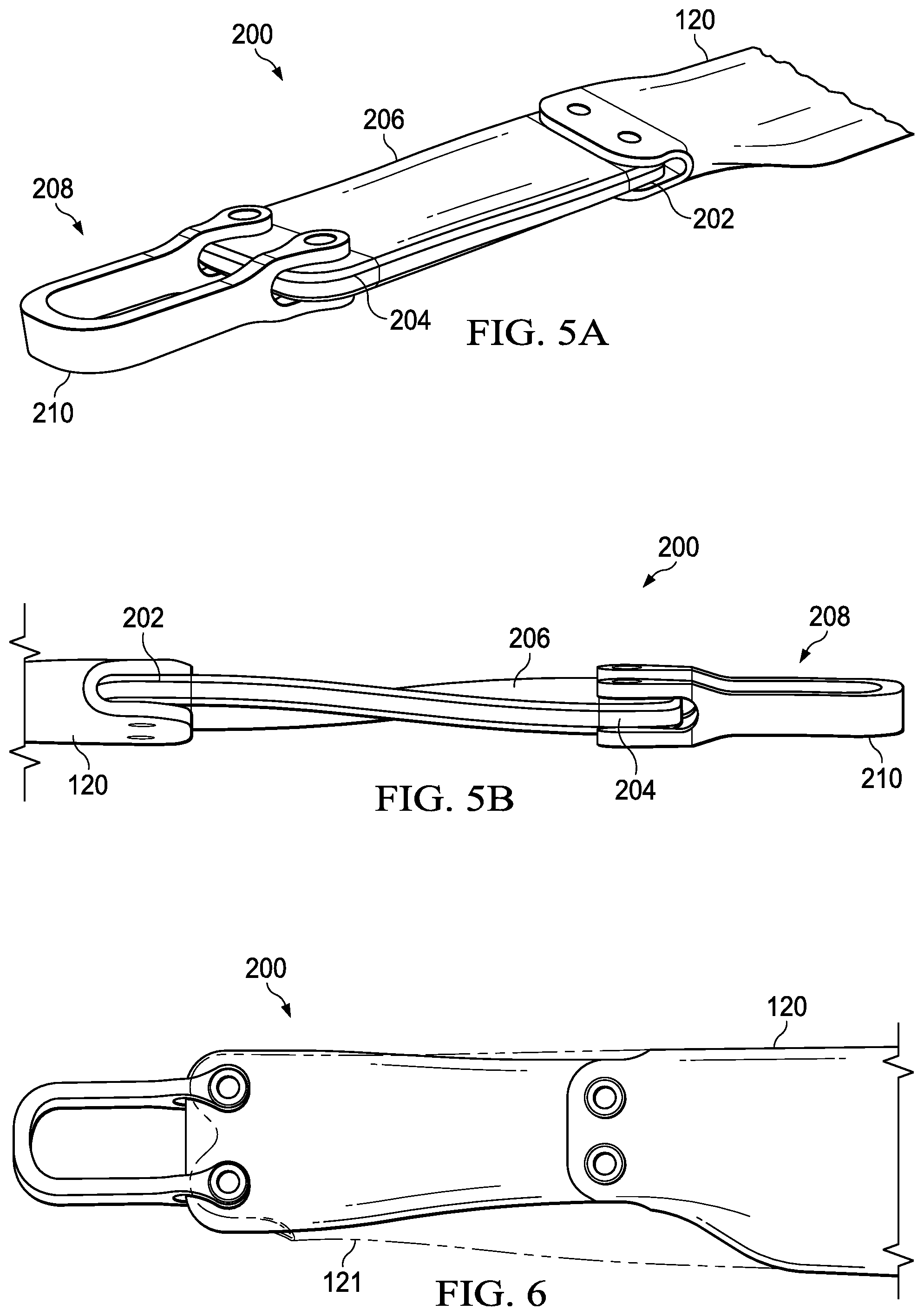
[0011] FIGS. 5A and 5B illustrate a rotor extension in accordance with aspects of the disclosure; and
[0012] FIG. 6 is a comparative view of a traditional rotor blade and a rotor blade that includes the rotor extension of FIGS. 5A and B in accordance with aspects of the disclosure.
DETAILED DESCRIPTION
[0013] It is to be understood that the following disclosure provides many different embodiments, or examples, for implementing different features of various embodiments. Specific examples of components and arrangements are described below to simplify the disclosure. These are, of course, merely examples and are not intended to be limiting. In addition, the disclosure may repeat reference numerals and/or letters in the various examples. This repetition is for the purpose of simplicity and clarity and does not in itself dictate a relationship between the various embodiments and/or configurations discussed.
[0014] In the specification, reference may be made to the spatial relationships between various components and to the spatial orientation of various aspects of components as the devices are depicted in the attached drawings. However, as will be recognized by those skilled in the art after a complete reading of the present disclosure, the devices, members, apparatuses, etc. described herein may be positioned in any desired orientation. Thus, the use of terms such as "above," "below," "upper," "lower," or other like terms to describe a spatial relationship between various components or to describe the spatial orientation of aspects of such components should be understood to describe a relative relationship between the components or a spatial orientation of aspects of such components, respectively, as the device described herein may be oriented in any desired direction.
[0015] FIG. 1 illustrates an example of a rotorcraft 100. Rotorcraft 100 includes a fuselage 102, a main rotor system 110 with rotor blades 120, and a tail rotor system 112 with tail rotor blades 122. An engine within fuselage 102 supplies main rotor system 110 and tail rotor system 112 with torque to rotate rotor blades 120 and tail rotor blades 122. A fairing 130 covers a rotor hub 134 (see FIG. 2) that couples rotor blades 120 to a mast 132. Fairing 130 improves the aerodynamic efficiency of rotorcraft 100 by reducing drag of rotor hub 134. As illustrated in FIG. 1, rotorcraft 100 includes four rotor blades 120. In other aspects, rotorcraft 100 could include as few as two or three rotor blades 120 or more than four rotor blades 120 (e.g., five, six, etc.). Landing gear 104 extend from fuselage 102 and support rotorcraft 100 when rotorcraft 100 is landing or when rotorcraft 100 is at rest on the ground. Rotorcraft 100 is not meant to be limiting. Aspects of the disclosure apply to other rotorcraft as well.
[0016] Generally speaking, the faster a rotor blade moves through the air and the greater an angle of attack of the rotor blade, the more lift that is generated. It will be appreciated that the speed of a rotor blade increases along a length of the rotor blade (known as the asymmetry of lift). In practical terms, the portion of a rotor blade proximal to the rotor hub tends to produce less lift (absent changes to the angle of attack resulting from specific rotor blade geometries) than the distal portion of a rotor blade due to the disparity in speed between the proximal and distal portions. This disclosure recognizes that a portion of the rotor blade proximal to the yoke/rotor hub can be replaced with a rotor extension that produces little to no lift without having a detrimental effect upon the amount of lift produced by the rotor blade. Replacing some of the proximal portion of the rotor blade with a rotor extension reduces drag to improve the aerodynamic efficiency of the aircraft, which is particularly desirable for high-speed helicopters.
[0017] In some aspects, utilizing rotor extensions can also reduce a cost of each rotor blade as some high-performance rotorcrafts utilize rotor blades made of expensive materials (e.g., composites). Costs are reduced because less material is needed to manufacture the rotor blade due to its shortened length and/or because the proximal portions of a rotor blade often comprise more complex shapes that are more costly to manufacture. Utilizing rotor extensions also allows for the fairing covering the rotor hub to be packaged more tightly and with smaller openings or cut-outs for the rotor blades as the cross-section of the rotor extension can be made smaller than the cross-section of a conventional rotor blade that attaches to the rotor hub without a rotor extension. Utilizing a rotor extension also creates a pivot point for blade fold that is positioned farther from the rotor hub, which allows the rotor blade to fully clear the rotor hub assembly for a compact blade fold. In some aspects, rotor blade 120 can be folded by removing one or more fasteners at an end of the rotor extension and pivoting rotor blade 120 about a remaining fastener.
[0018] FIGS. 2A and 2B are top and side views, respectively, of main rotor system 110 according to aspects of the disclosure. Main rotor system 110 includes a fairing 130 that encloses rotor hub 134 to reduce the drag of main rotor system 110. Each rotor blade 120 is coupled to rotor hub 134 via a rotor extension 124. In various aspects, rotor extension 124 may be coupled to the yoke, mast, or other rotating component. Fairing 130 includes cut-outs 126 that permit rotor extensions 124 to pass through. Each cut-out 126 is dimensioned to accommodate a range of motion of the rotor extension 124 that passes therethrough. For example, during flight, rotor blades 120 pivot about their coupling to rotor hub 134 as a result of various dynamic forces such as flapping, coning, lead/lag, pitch, and the like. Cut-outs 126 are dimensioned to be just large enough to allow for the various movements of rotor blades 120 while minimizing the size of cut-outs 126 to improve the aerodynamic efficiency of fairing 130.
[0019] FIGS. 3A and 3B are perspective views of rotor extension 124. FIG. 3A illustrates an uninstalled rotor extension 124 and FIG. 3B illustrates rotor extension 124 attached to rotor blade 120. Each rotor extension 124 includes a first connector 136, a shaft 138, and a second connector 140. As illustrated in FIGS. 3A and 3B, first connector 136 is a tongue 136 and second connector 140 is a clevis 140. In other aspects, first and second connectors may comprise other connector types. In some aspects, rotor extension 124 may include a damper mount 142 attached to shaft 138 or clevis 140 for attaching a damper to rotor extension 124. In some aspects, shaft 138 or clevis 140 may include a pitch horn that couples to a pitch link to control a pitch of rotor blade 120. Rotor extension 124 may be made of various materials, including titanium, steel, aluminum, metal matrix composite, composites, and the like.
[0020] Tongue 136 includes one or more mounting holes 144 that receive fasteners (e.g., a pin, a screw, a bolt, and the like) to secure rotor extension 124 to rotor blade 120. As illustrated in FIGS. 3A and 3B, tongue 136 is configured to fit inside of an opening in an end of rotor blade 120. As illustrated in FIG. 3B, the opening in the end of rotor extension 124 is formed so that an outer profile of rotor blade 120 is not altered and an outer surface of rotor blade 120 remains smooth and unobstructed by connection of rotor extension 124 to rotor blade 120. Rotor blade 120 includes corresponding mounting holes 146 that align with the one or more mounting holes 144. In other aspects, tongue 136 may instead attached to an exterior portion of rotor blade 120.
[0021] Rotor blade 120 may be folded about tongue 136 by removing a fastener from the connection between rotor blade 120 and tongue 136. Rotor extension 124 allows for a compact blade fold as the pivot point about tongue 136 is sufficiently far away from rotor hub 134 to allow the rotor blades 120 to clear fairing 130.
[0022] Shaft 138 joins tongue 136 with clevis 140. In some aspects, shaft 138 is a hollow tube to reduce a weight of rotor extension 124. Clevis 140 is disposed on an end of shaft 138 opposite tongue 136 and couples to rotor hub 134. In a typical aspect, rotor extension 124 couples to rotor hub 134 via a bearing assembly that includes an inboard beam and a centrifugal force bearing. As illustrated in FIGS. 3A and 3B, clevis 140 is arranged generally vertically. It will be appreciated that clevis 140 could be arranged horizontally or at an angle between horizontal and vertical as needed to allow for rotor extension 124 to attach to a particular rotor hub. In some aspects, clevis 140 could be replaced with an alternative connection suited to a particular rotor hub.
[0023] Shaft 138 may have a variety of cross-sections, including circular, elliptical, rectangular, polygonal, and the like. As illustrated in FIGS. 3A and 3B, shaft 138 has a circular cross-section. Shaft 138 has a cross-section that is notably smaller than that of a conventional rotor blade (e.g., see FIG. 4), which allows the size of cut-outs 126 to be minimized. Having a circular cross-section enables rotor extension 124 to maintain its projected frontal area regardless of the pitch of the rotor blade 120, resulting in a consistent amount of drag generated by shaft 138 regardless of pitch angle. It has been determined that the benefits of minimizing the size of the opening of cut-out 126 outweighs the benefits of using a more aerodynamic shaft 138. For example, using an elliptical cross-section on shaft 138 improves the aerodynamics of the portion of shaft 138 that is outside fairing 130. However, an elliptical cross-section increases the size of cut-out 126. The increase in drag resulting from the larger cut-out 126 results in a net increase in the drag acting on rotorcraft 100.
[0024] In some aspects, shaft 138 comprises more than one cross-section to overcome the potential drawbacks of using an elliptical cross-section. For example, a portion of shaft 138 that passes through cut-out 126 may comprise a first cross-section (e.g., circular) and a portion of shaft 138 disposed outside of fairing 130 may comprise a second cross-section (e.g., elliptical). Using a circular cross-section for the first cross-section minimizes a size of cut-out 126 and using an elliptical cross-section for the second cross-section optimizes aerodynamics of the portion of shaft 138 disposed outside of fairing 130.
[0025] In some aspects, shaft 138 comprises a first cross-section (e.g., circular) and a portion of shaft 138 located outside of fairing 130 includes an extension fairing 178 fitted to shaft 138 to improve the aerodynamics of the portion of shaft 138 located outside fairing 130. Extension fearing 178 may comprise an elliptical shape, a blade-like shape, or other aerodynamic shape to minimize the drag created by the portion of shaft 138 located outside fairing 130. Extension fairing 178 can be a removable piece that attaches to rotor extension 124 via fasteners, adhesives, and the like, or can be integrally formed as a part of rotor extension 124.
[0026] In various aspects, tongue 136 and clevis 140 are set at an angle relative to each other to add an amount of blade twist to rotor extension 124. Blade twist describes a geometric twist along a length of the rotor blade to change the rotor blade's pitch along the length of the rotor blade to combat asymmetry of lift. Pitch is decreased as the distance from the hub increases to even out the amount of thrust generated along the length of the rotor blade. FIGS. 3A and 3B illustrate that a face 137 of tongue 136 and a face 141 of clevis 140 are arranged at an angle relative to one another (e.g., not parallel to one another) to introduce an amount of blade twist to rotor blade 120. In some aspects, approximately 10 degrees of blade twist as added via extension 124. In other aspects, more than 10 degrees or less than 10 degrees of blade twist may be added by rotor extension 124. Introducing blade twist via rotor extension 124 may be desirable as the amount of blade twist added by rotor extension 124 does not need to be added to rotor blade 120, which is typically made from expensive composite materials. To incorporate blade twist into the design of rotor blade 120 adds complexity to the structure of rotor blade 120, adding to its cost. In some aspects, rotor extension 124 may be designed without any blade twist, with faces 137 and 141 parallel to one another.
[0027] FIG. 4 is a top view of a conventional rotor blade 121 overlaid on top of a combination of rotor extension 124 attached to rotor blade 120. FIG. 4 illustrates the reduction in surface area, and thus the reduction in drag, afforded by using rotor extension 124.
[0028] FIGS. 5A-5B illustrate a rotor extension 200 according to aspects of the disclosure. In various aspects, rotor extension 200 may be used in place of rotor extension 124. Compared to rotor extension 124, rotor extension 200 has a flat, blade-like shape. Rotor extension 200 reduces drag compared to a conventional rotor blade by having a lower profile shape (e.g., see FIG. 6). Each rotor extension 200 includes a tongue 202 and a tongue 204 that are disposed on opposite ends of an extension portion 206. Rotor extension 200 may be made of various materials, including titanium, steel, aluminum, metal matrix composite, composites, and the like. In some aspects, rotor extension 200 is made from carbon fiber, fiberglass, or a combination of the two.
[0029] Tongue 202 includes one or more mounting holes that receive fasteners to secure rotor extension 200 to rotor blade 120 and tongue 204 includes one or more mounting holes that receive fasteners to secure rotor extension 200 to a yoke attachment 208. Fasteners can be pins, screws, bolts, and the like. Yoke attachment 208 includes corresponding mounting holes that align with the one or more mounting holes of tongue 204. As illustrated in FIGS. 5A and 5B, yoke attachment 208 comprises a body portion 210 that couples to rotor hub to secure rotor blade 120 thereto. In a typical aspect, yoke attachment 208 couples to the rotor hub via a bearing assembly, such as a centrifugal bearing assembly.
[0030] In various aspects, tongue 202 and tongue 204 are set at an angle relative to each other to add an amount of blade twist to rotor extension 200 (best seen in FIG. 5B). Introducing blade twist via rotor extension 200 may be desirable as the amount of blade twist added by rotor extension 200 does not need to be added to rotor blade 120, simplifying the shape of rotor blade 120, which is typically made from expensive composite materials. To incorporate blade twist into the design of rotor blade 120 adds complexity to the structure of rotor blade 120, adding to its cost. In some aspects, rotor extension 200 may be designed without any blade twist.
[0031] FIG. 6 is a perspective view of a conventional rotor blade 121 overlaid on top of a combination of rotor extension 200 attached to rotor blade 120. FIG. 6 illustrates the reduction in surface area/size, and thus the reduction in drag, afforded by using rotor extension 200.
[0032] Depending on the embodiment, certain acts, events, or functions of any of the algorithms, methods, or processes described herein can be performed in a different sequence, can be added, merged, or left out altogether (e.g., not all described acts or events are necessary for the practice of the algorithms, methods, or processes). Moreover, in certain embodiments, acts or events can be performed concurrently, e.g., through multi-threaded processing, interrupt processing, or multiple processors or processor cores or on other parallel architectures, rather than sequentially. Although certain computer-implemented tasks are described as being performed by a particular entity, other embodiments are possible in which these tasks are performed by a different entity.
[0033] Conditional language used herein, such as, among others, "can," "might," "may," "e.g.," and the like, unless specifically stated otherwise, or otherwise understood within the context as used, is generally intended to convey that certain embodiments include, while other embodiments do not include, certain features, elements and/or states. Thus, such conditional language is not generally intended to imply that features, elements and/or states are in any way required for one or more embodiments or that one or more embodiments necessarily include logic for deciding, with or without author input or prompting, whether these features, elements and/or states are included or are to be performed in any particular embodiment.
[0034] The term "substantially" is defined as largely but not necessarily wholly what is specified (and includes what is specified; e.g., substantially 90 degrees includes 90 degrees and substantially parallel includes parallel), as understood by a person of ordinary skill in the art. In any disclosed embodiment, the terms "substantially," "approximately," "generally," "generally in the range of," and "about" may be substituted with "within [a percentage] of" what is specified, as understood by a person of ordinary skill in the art. For example, within 1%, 2%, 3%, 5%, and 10% of what is specified herein.
[0035] While the above detailed description has shown, described, and pointed out novel features as applied to various embodiments, it will be understood that various omissions, substitutions, and changes in the form and details of the devices or algorithms illustrated can be made without departing from the spirit of the disclosure. As will be recognized, the processes described herein can be embodied within a form that does not provide all of the features and benefits set forth herein, as some features can be used or practiced separately from others. The scope of protection is defined by the appended claims rather than by the foregoing description. All changes which come within the meaning and range of equivalency of the claims are to be embraced within their scope.
* * * * *
D00000
D00001
D00002
D00003
D00004
XML
uspto.report is an independent third-party trademark research tool that is not affiliated, endorsed, or sponsored by the United States Patent and Trademark Office (USPTO) or any other governmental organization. The information provided by uspto.report is based on publicly available data at the time of writing and is intended for informational purposes only.
While we strive to provide accurate and up-to-date information, we do not guarantee the accuracy, completeness, reliability, or suitability of the information displayed on this site. The use of this site is at your own risk. Any reliance you place on such information is therefore strictly at your own risk.
All official trademark data, including owner information, should be verified by visiting the official USPTO website at www.uspto.gov. This site is not intended to replace professional legal advice and should not be used as a substitute for consulting with a legal professional who is knowledgeable about trademark law.