Modular Flotation Device With Mechanism To Removably Attach To Other Modular Devices
ANDERSEN; Mike Kirk ; et al.
U.S. patent application number 16/979107 was filed with the patent office on 2020-12-24 for modular flotation device with mechanism to removably attach to other modular devices. The applicant listed for this patent is Mike Kirk ANDERSEN, Theresa M. BANNON, Matthew James CALLAHAN, Justin Chyun CHANG, Joshua Lee FINKLE, Nichole HOWELL, Vlasta Anastasia KOMOROUS-KING, Michelle Sau Kuen LEE-SCHMIDT, Chenyu LIU, Steven James MOORE, Carl R. ROMULUS, James Adam SKAATES, Andrew Richardson STEWART, David Jason WILKINS. Invention is credited to Mike Kirk ANDERSEN, Theresa M. BANNON, Matthew James CALLAHAN, Justin Chyun CHANG, Joshua Lee FINKLE, Nichole HOWELL, Vlasta Anastasia KOMOROUS-KING, Michelle Sau Kuen LEE-SCHMIDT, Chenyu LIU, Steven James MOORE, Carl R. ROMULUS, James Adam SKAATES, Andrew Richardson STEWART, David Jason WILKINS.
| Application Number | 20200398946 16/979107 |
| Document ID | / |
| Family ID | 1000005089907 |
| Filed Date | 2020-12-24 |


View All Diagrams
| United States Patent Application | 20200398946 |
| Kind Code | A1 |
| ANDERSEN; Mike Kirk ; et al. | December 24, 2020 |
MODULAR FLOTATION DEVICE WITH MECHANISM TO REMOVABLY ATTACH TO OTHER MODULAR DEVICES
Abstract
One or more embodiments disclosed herein relate generally to flotation devices, and more specifically to modular flotation devices with a mechanism to removably attach to other modular devices. In one embodiments, an apparatus includes a first flotation module and a first connector coupled to the first flotation module. The first connector has a first end portion, a second end portion and a sidewall extended from the first end portion to the second end portion. The sidewall defines a plurality of circumferentially defined stepped portions configured to matingly engage a second connector of a second flotation module to couple the first flotation module to the second flotation module. The first connector is selectively operative as one of a female connector or a male connector with respect to the second connector.
| Inventors: | ANDERSEN; Mike Kirk; (Palo Alto, CA) ; BANNON; Theresa M.; (Virginia Beach, VA) ; CALLAHAN; Matthew James; (San Francisco, CA) ; CHANG; Justin Chyun; (Studio City, CA) ; FINKLE; Joshua Lee; (Menlo Park, CA) ; HOWELL; Nichole; (Virginia Beach, VA) ; KOMOROUS-KING; Vlasta Anastasia; (Berkeley, CA) ; LEE-SCHMIDT; Michelle Sau Kuen; (San Francisco, CA) ; LIU; Chenyu; (San Jose, CA) ; MOORE; Steven James; (San Mateo, CA) ; ROMULUS; Carl R.; (Virginia Beach, VA) ; SKAATES; James Adam; (San Francisco, CA) ; STEWART; Andrew Richardson; (San Francisco, CA) ; WILKINS; David Jason; (San Francisco, CA) | ||||||||||
| Applicant: |
|
||||||||||
|---|---|---|---|---|---|---|---|---|---|---|---|
| Family ID: | 1000005089907 | ||||||||||
| Appl. No.: | 16/979107 | ||||||||||
| Filed: | May 6, 2019 | ||||||||||
| PCT Filed: | May 6, 2019 | ||||||||||
| PCT NO: | PCT/US2019/030945 | ||||||||||
| 371 Date: | September 8, 2020 |
Related U.S. Patent Documents
| Application Number | Filing Date | Patent Number | ||
|---|---|---|---|---|
| 62639752 | Mar 7, 2018 | |||
| Current U.S. Class: | 1/1 |
| Current CPC Class: | B63B 34/565 20200201 |
| International Class: | B63B 34/565 20060101 B63B034/565 |
Claims
1. An apparatus, comprising: a first flotation module, and a first connector coupled to the first flotation module, the first connector having a first end portion, a second end portion and a sidewall extended from the first end portion to the second end portion, the sidewall defining a plurality of circumferentially defined stepped portions configured to matingly engage a second connector of a second flotation module to couple the first flotation module to the second flotation module, the first connector being selectively operative as one of a female connector or a male connector with respect to the second connector.
2. The apparatus of claim 1, wherein the first connector is, concurrently with the selective operation of the first connector as one of the female connector or the male connector with respect to the second connector, selectively operative as the other of a female connector or a male connector with respect to a third connector.
3. The apparatus of claim 1, wherein the first connector is configured to concurrently matingly engage the second connector of the second flotation module and to matingly engage a third connector of a third flotation module to couple the first flotation module and the second flotation module to the third flotation module.
4. The apparatus of claim 1, wherein the connector includes a cup-shaped body portion having a circumference at the first end portion and a circumference at the second end portion less than the circumference at the first end portion.
5. The apparatus of claim 1, wherein the first flotation module is a first chair configured to support a first user in a seated position in water and the second flotation module is a second chair configured to support a second user in a seated position in water.
6. The apparatus of claim 1, wherein the first flotation module is a chair, and the second flotation module is a table, shelf, or sunshade.
7. The apparatus of claim 1, wherein the first connector is operatively coupleable to the second connector at a plurality of rotational positions about a center axis of the first connector.
8. The apparatus of claim 1, wherein the first connector is configured to be in a stacked relationship with respect to the second connector.
9. The apparatus of claim 1, wherein the first connector is configured to be concurrently coupled in a stacked relationship to a plurality of connectors, the plurality of connectors including the second connector.
10. An apparatus, comprising: a first flotation module; and a first connector coupled to the first flotation module, the first connector including a body portion having a first end portion, a second end portion, and a sidewall portion extended from the first end portion to the second end portion, the first end portion of the body portion having a first perimeter and defining an opening in communication with an interior volume of the body portion, the second end portion of the body portion having a second perimeter less than the first perimeter, the first connector configured to (1) at least partially receive in the interior volume, at a first time, a complementary body portion of a second connector of a second flotation module to removably couple the first flotation module to the second flotation module at the first time, and (2) be at least partially received, at a second time different from the first time, in the body portion of the second connector of the second flotation module to removably couple the first flotation module to the second flotation module at the second time.
11. The apparatus of claim 10, wherein the sidewall defines a stepped portion circumferentially disposed about the body portion at a location between the first end portion and the second end portion.
12. The apparatus of claim 10, wherein the sidewall defines a plurality of steps configured to complementarily fit a plurality of steps of the second connector of the second flotation module to couple the first flotation module to the second flotation module.
13. The apparatus of claim 10, wherein the first connector is configured to at least partially receive in the interior volume a third connector of a third flotation module concurrently with the first connector being at least partially received, at the second time, in the body portion of the second connector of the second flotation module to removably couple the first flotation module and the second flotation module to the third flotation module.
14. The apparatus of claim 10, wherein the first connector is configured to be at least partially received in a third connector of a third flotation module concurrently with the first connector at least partially receiving in the interior volume, the complementary body portion of the connector of the second flotation module to removably couple the first flotation module and the second flotation module to the third flotation module.
15. The apparatus of claim 10, wherein the first connector includes a rim portion having a first layer and a second layer, the rim portion including a prong extended from the first layer, the second layer defining an opening configured to receive at least a portion of the prong.
16. The apparatus of claim 10, wherein the first flotation module is inflatable.
17. The apparatus of claim 10, wherein the first flotation module is a first chair configured to support a first user in a seated position in water and the second flotation module is a second chair configured to support a second user in a seated position in water.
18. The apparatus of claim 10, wherein the first flotation module is a chair, and the second flotation module is a table, shelf, or sunshade.
19. The apparatus of claim 10, wherein the first connector and the second connector are coupled by a friction fit when the first connector (1) at least partially receives in the interior volume the complementary body portion of the second connector at the first time, or (2) is at least partially received in the complementary body portion of the second connector at the second time.
20. The apparatus of claim 10, wherein the first connector is configured to be coupled to the second connector at a plurality of rotational positions about a center axis of the body portion of the first connector.
Description
CROSS-REFERENCE TO RELATED APPLICATION
[0001] This application claims priority to and the benefit of U.S. provisional patent application No. 62/639,752, entitled "Modular Flotation Device With Mechanism To Removably Attach To Other Modular Devices," filed on Mar. 7, 2018, the entirety of which is incorporated by reference herein.
BACKGROUND
[0002] Known flotation devices either do not provide a way to removably attach to other devices or do not provide an attachment mechanism that is common on multiple flotation devices. Thus, a need exists to provide modular flotation devices with a mechanism to removably attach to other modular devices.
SUMMARY
[0003] One or more embodiments disclosed herein relate generally to flotation devices, and more specifically to modular flotation devices with a mechanism to removably attach to other modular devices. In one embodiment, a device (or apparatus) includes a first flotation module and a first connector coupled to the first flotation module. The first connector has a first end portion, a second end portion and a sidewall extended from the first end portion to the second end portion. The sidewall defines a plurality of circumferentially defined stepped portions configured to matingly engage a second connector of a second flotation module to couple the first flotation module to the second flotation module. The first connector is selectively operative as one of a female connector or a male connector with respect to the second connector.
BRIEF DESCRIPTION OF THE DRAWINGS
[0004] FIG. 1 shows a front perspective view of a modular flotation device, according to an embodiment.
[0005] FIG. 2 shows a perspective view of five modular flotation devices that have been connected in series to form a loop, according to an embodiment.
[0006] FIG. 3 shows a perspective view of a modular shelf, according to an embodiment.
[0007] FIG. 4 shows a perspective view of a modular table, according to an embodiment.
[0008] FIG. 5 shows a perspective view of two modular flotation devices removably coupled to the modular shelf of FIG. 3 and the modular table of FIG. 4.
[0009] FIG. 6 shows a perspective view of a modular flotation device removably coupled to a modular sunshade, according to an embodiment.
[0010] FIG. 7 shows a perspective view of a modular flotation device removably coupled to a modular sunshade, according to another embodiment.
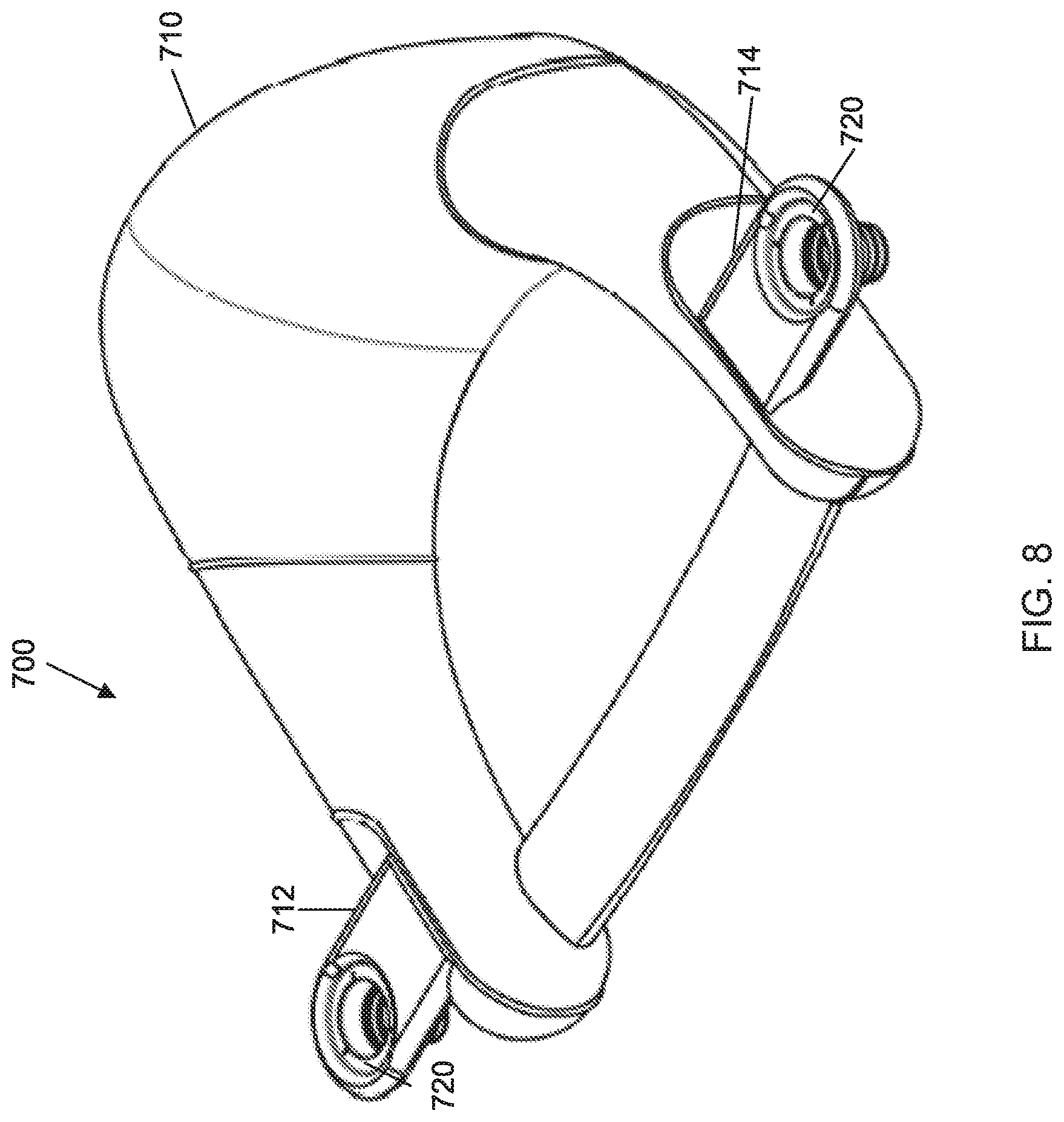
[0011] FIG. 8 shows a perspective view of a modular flotation device similar to the modular flotation device FIG. 1.
[0012] FIGS. 9 and 10 show a front view and a rear view, respectively, of the modular flotation device of FIG. 8.
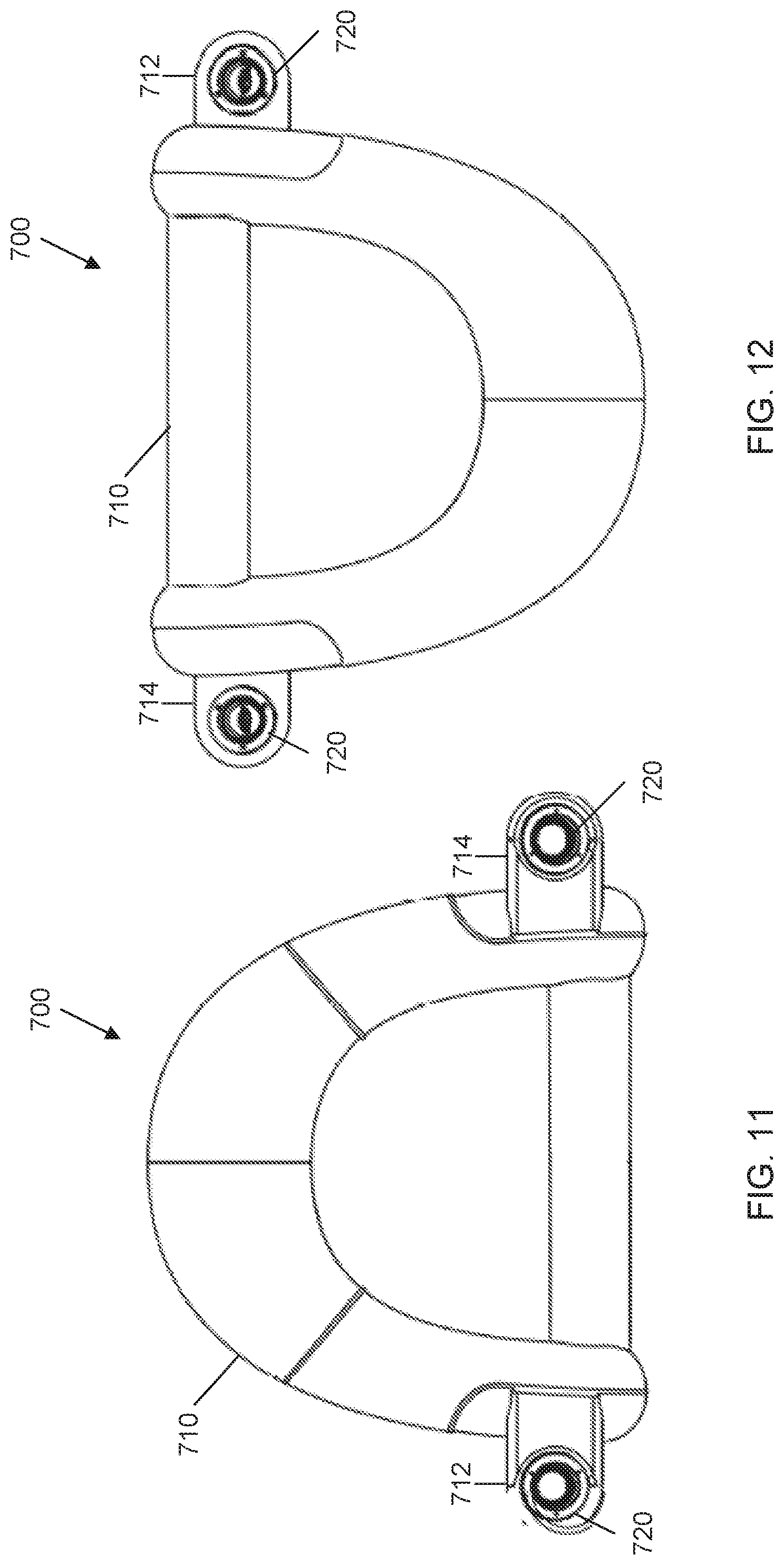
[0013] FIGS. 11 and 12 show a top view and a bottom view, respectively, of the modular flotation device of FIG. 8.
[0014] FIGS. 13 and 14 show a left view and a right view, respectively, of the modular flotation device of FIG. 8.
[0015] FIGS. 15 and 16 show a top perspective view and a bottom perspective view, respectively, of an attachment mechanism, according to an embodiment.
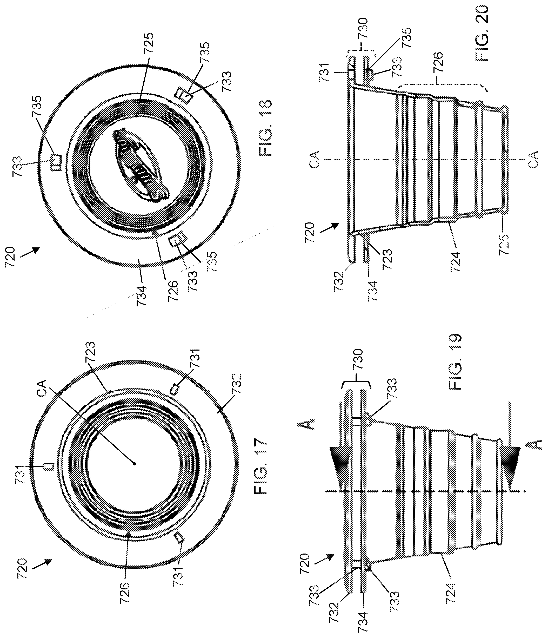
[0016] FIGS. 17 and 18 show a top view and a bottom view, respectively, of the attachment mechanism of FIG. 15.
[0017] FIG. 19 is a side view of the attachment mechanism of FIG. 15.
[0018] FIG. 20 is a cross-sectional view along line AA of the attachment mechanism of FIG. 19.
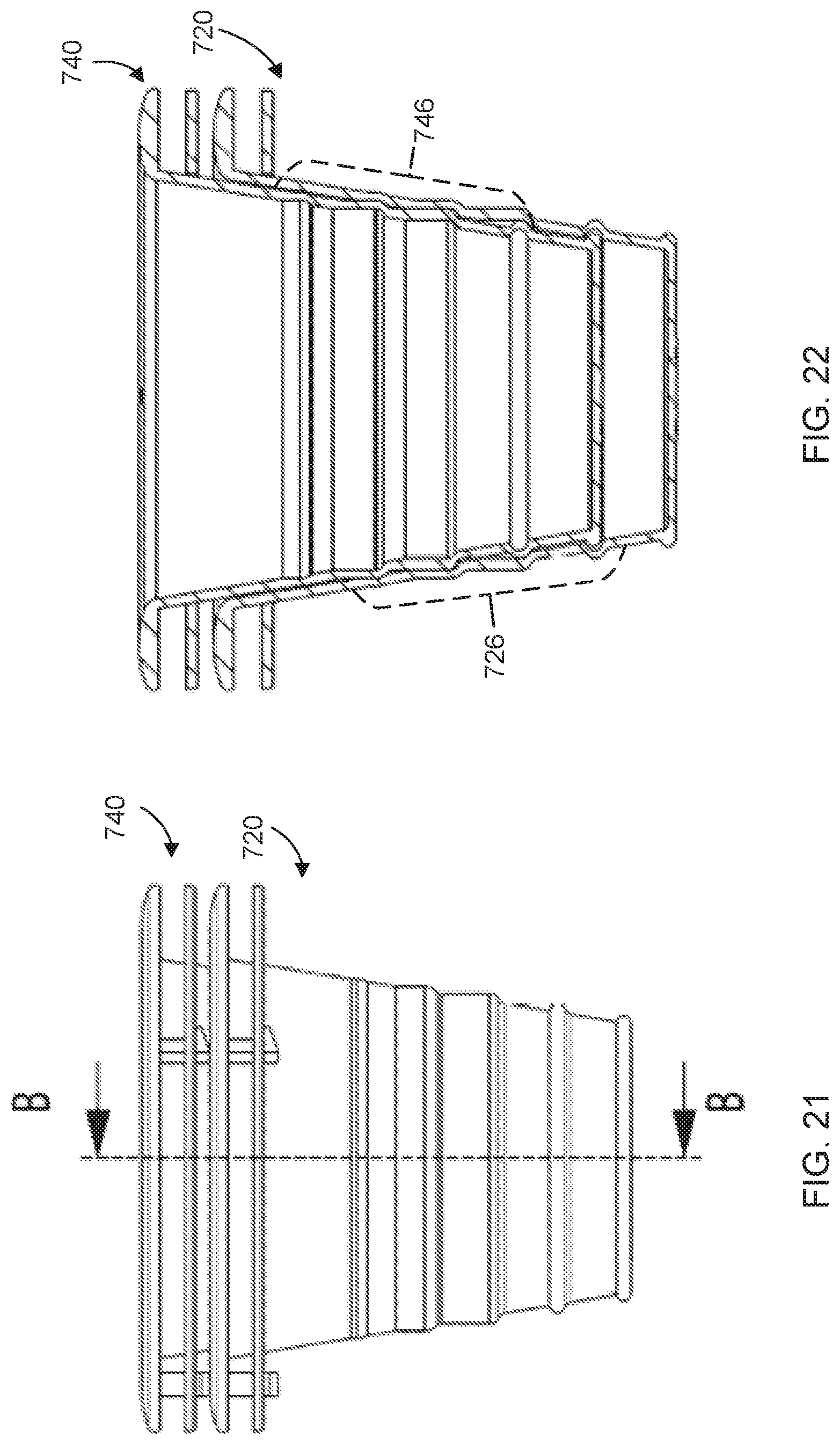
[0019] FIG. 21 is a side view of two attachment mechanisms of FIG. 15, one received within the other.
[0020] FIG. 22 is a cross-sectional view along line BB of the two attachment mechanisms of FIG. 21.
[0021] FIGS. 23, 24 and 25 are a top view, a front view and a side view, respectively, of a modular shelf similar to the modular shelf shown in FIG. 3.
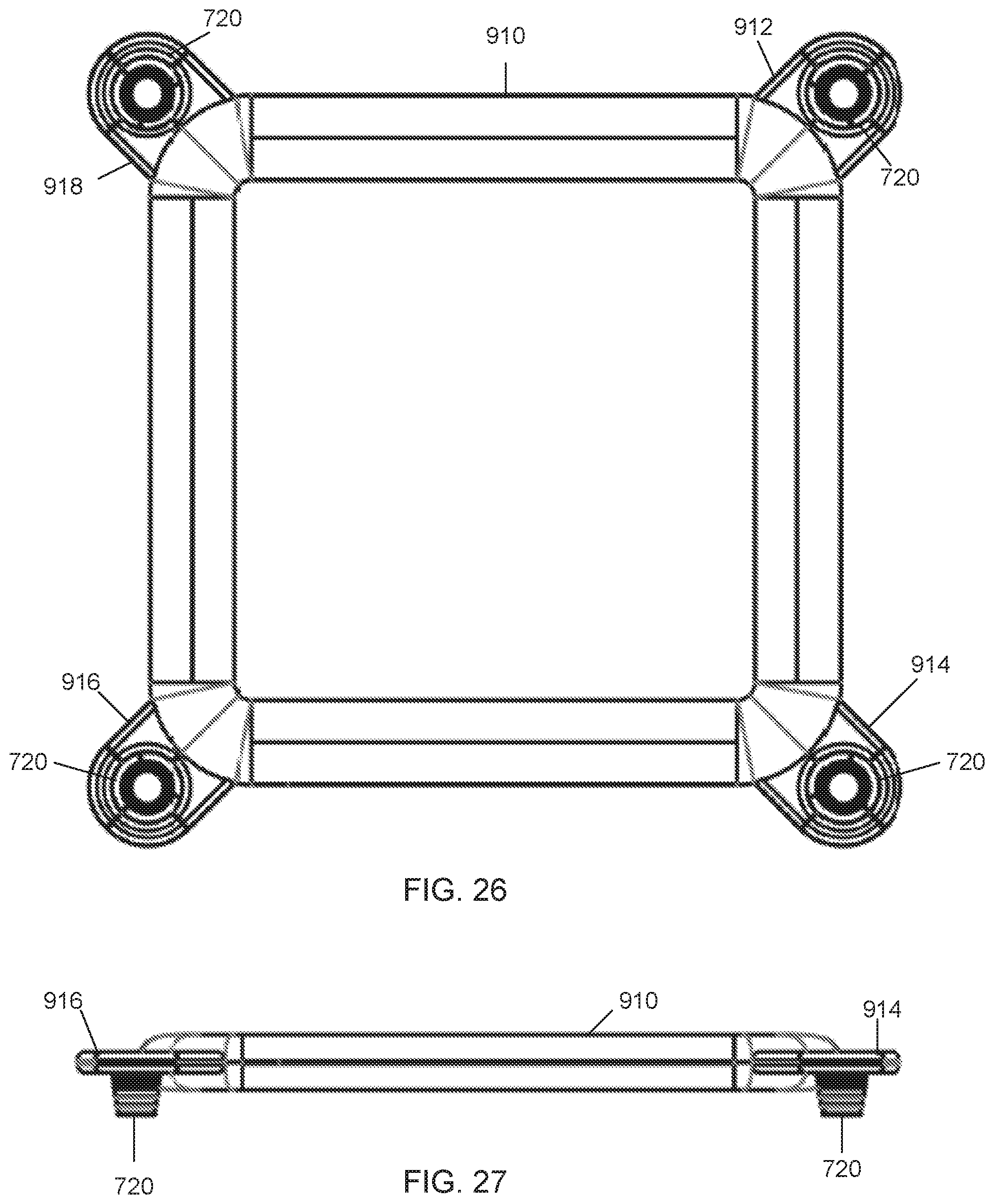
[0022] FIGS. 26 and 27 are a top view and a front view, respectively, of a modular table similar to the modular table shown in FIG. 4.
DETAILED DESCRIPTION
[0023] One or more embodiments disclosed herein relate to modular flotation devices (or flotation modules) with a mechanism to removably attach to other modular flotation devices (or flotation modules). The attachment mechanism can be, for example, a projection having a chamber or receptacle (or interior volume) that can receive the projection from another module flotation device. For example, the attachment mechanism can be connector that has a cup-like structure having a tapered shape with a larger size opening at the top portion, a sidewall that tapers down in a smaller size surface at the bottom portion. The tapered shape of the attachment mechanism allows for the attachment mechanism of one modular flotation device to be placed on top of (stacked) and received within the chamber or receptacle (or interior volume) of another module flotation device.
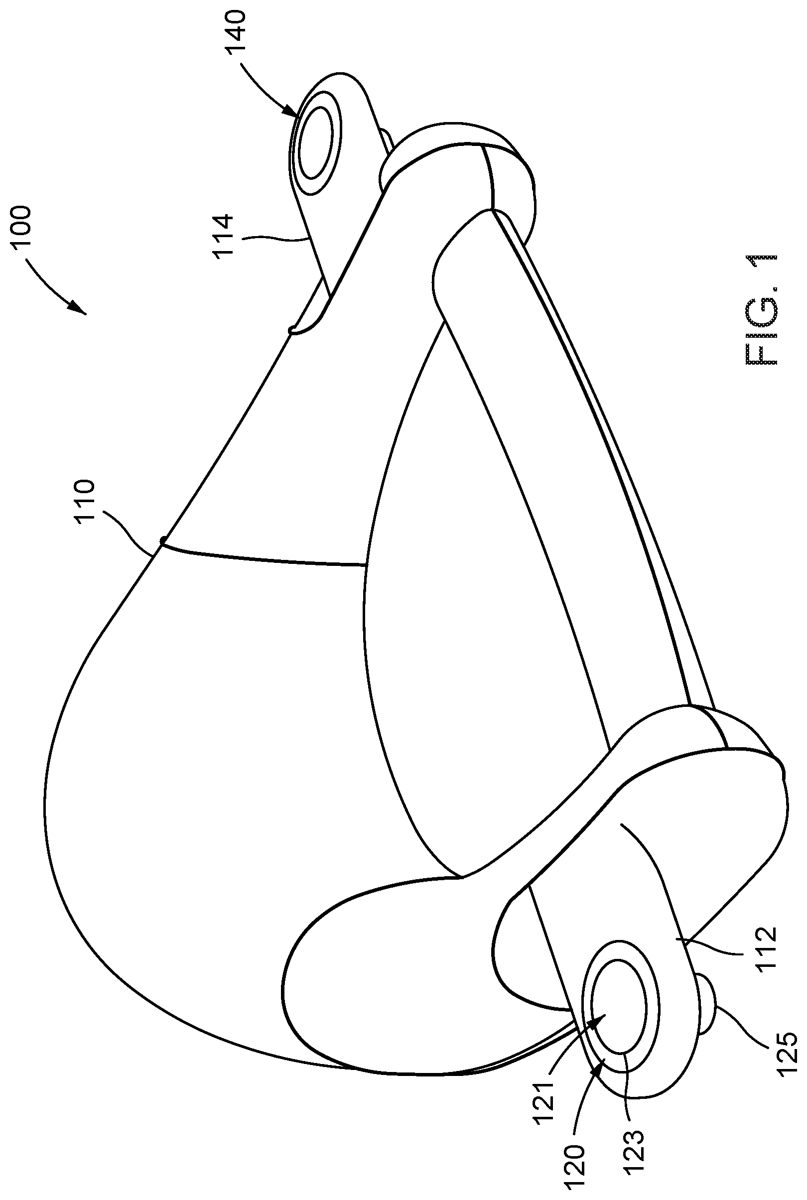
[0024] FIG. 1 shows a front perspective view of a modular flotation device (or flotation module), according to an embodiment. As shown in FIG. 1, the modular flotation device 100 includes a chair portion 110, an extension portion 112 on one side of the chair portion 110, and an extension portion 114 on the other side of the chair portion 110. The chair portion 110 is configured to support a user in a seated position in water. Extension portion 112 includes an attachment mechanism (or connector) 120; extension portion 114 includes an attachment mechanism (or connector) 140. The modular flotation device 100 can be made, for example, of polyvinyl chloride (PVC) that defines an inflatable bladder having an expanded configuration (shown in FIG. 1) and a collapsed configuration (not shown). The modular flotation device 100 can optionally include a fabric covering disposed over the PVC bladder.
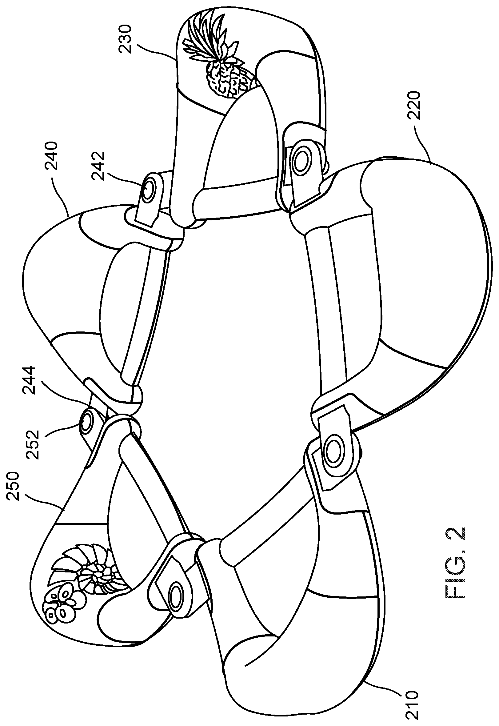
[0025] Each of attachment mechanisms (or connectors) 120 and 140 has a cup-like structure with a top or first end portion, a second end or bottom portion, and a sidewall extended from the first end portion to the second end portion. The attachment mechanism 120, 140 has a tapered shape with a larger size opening at the top (or first end) portion, and the sidewall tapering down towards a smaller size surface at the bottom (or second end) portion. The tapered shape of the attachment mechanisms 120 and 140 allows for the attachment mechanism of one modular flotation device to be placed on top of (stacked) and received within the chamber or receptacle (or interior volume) 121 of another modular flotation device (or flotation module). In this manner, the attachment mechanisms of two distinct modular flotation devices are coupled in a stacked relationship. For example, FIG. 2 shows a perspective view of five modular flotation devices that have been connected in a series to form a loop, according to an embodiment.
[0026] More specifically, FIG. 2 shows five modular flotation devices 210, 220, 230, 240, 250, each of which is similar to the modular flotation device 100 shown in FIG. 1. Any given modular flotation device 210, 220, 230, 240, 250 of FIG. 2 is removably attached to an adjacent modular flotation device on one side and another adjacent modular flotation device on the other side. For example, the attachment mechanism (or connector) 242 on one side of modular flotation device 240 is received in the attachment mechanism (or connector) (not shown) of modular flotation device 230 while the attachment mechanism (or connector) 244 on the other side of modular flotation device 240 receives the attachment mechanism (or connector) 252 of modular flotation device 250. Although modular flotation device 240 is shown as both receiving the attachment mechanism 252 of one modular flotation device 250 and being received in the attachment mechanism of another modular flotation device 230, it should be understood that both attachment mechanisms of a modular flotation device can receive an attachment mechanism of both adjacent modular flotation devices (as shown in FIG. 2 with respect to modular flotation devices 230 and 210) or be received by an attachment mechanism of both adjacent modular flotation devices (as shown in FIG. 2 with respect to modular flotation devices 220 and 250). Said another way, each attachment mechanism can be selectively operative as one of a female connector or a male connector with respect to another attachment mechanism. The modular flotation devices 210, 220, 230, 240, 250 are shown as chairs configured to support users in a seated position in water.
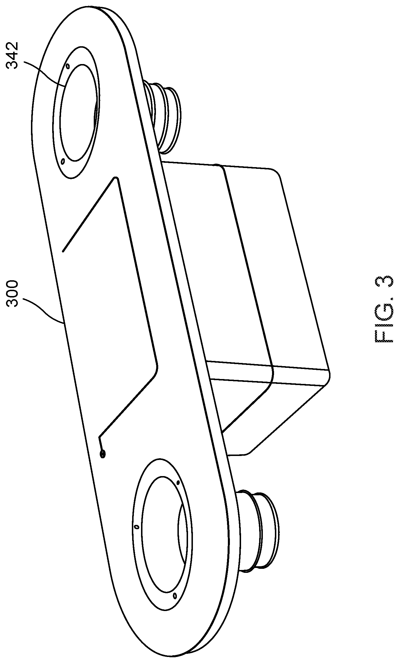
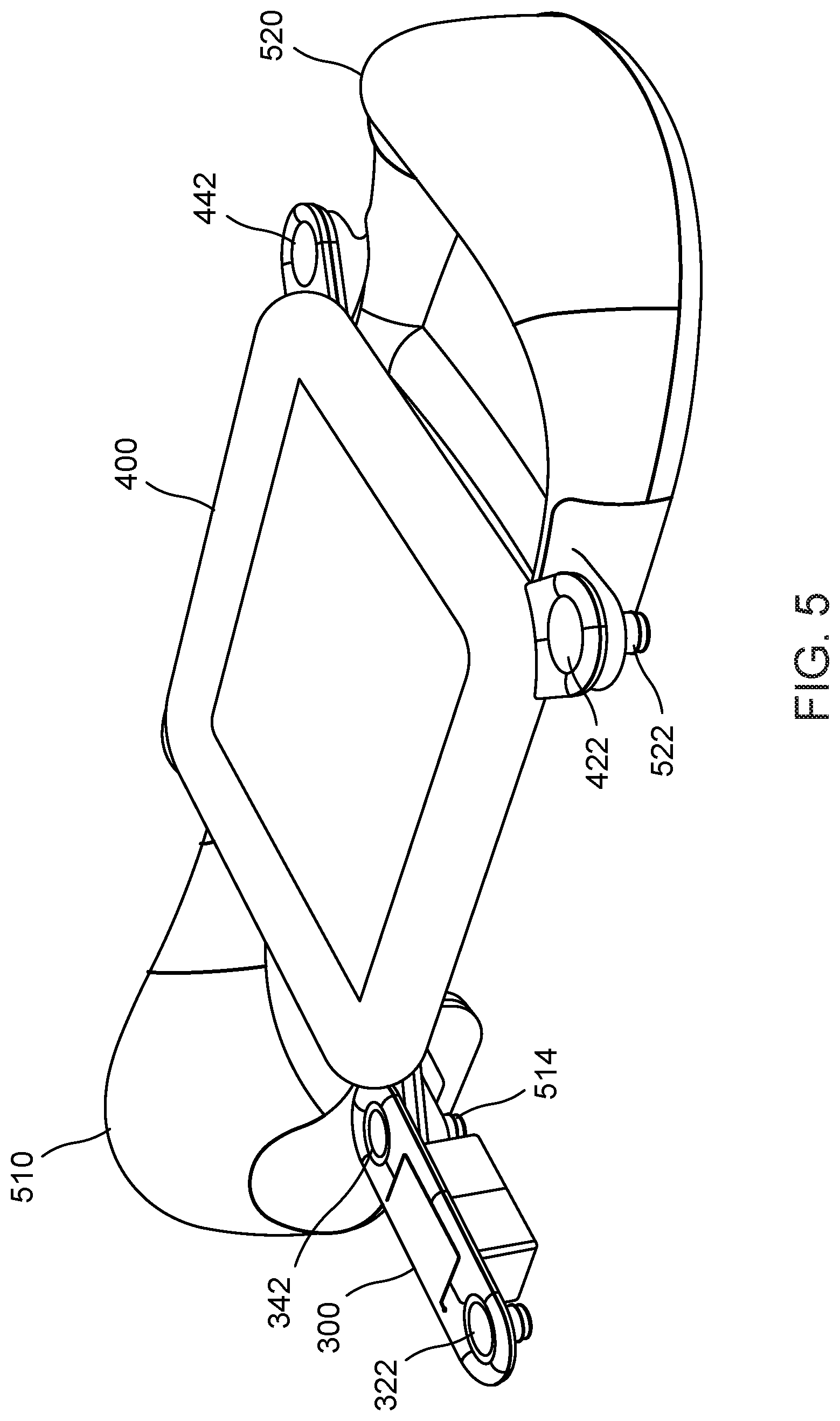
[0027] Rather than solely removably attaching to another modular flotation device, a modular flotation device can, alternatively or additionally, removably attach to different types of modular devices (or flotation modules) such as a modular shelf 300 as shown in FIG. 3, a modular table 400 as shown in FIG. 4, or a modular sunshade 620 as shown in FIG. 6. For example, FIG. 5 shows a perspective view of two modular flotation devices removably coupled to a modular shelf and a modular table. The two modular flotation devices (or flotation modules) 510, 520 of FIG. 5 are each similar to the modular flotation device 100 of FIG. 1. As shown in FIG. 5, the two attachment mechanisms 522 (other not shown in FIG. 5) of modular flotation device 520 receive (e.g., selectively operate as female connectors with respect to) two attachment mechanisms 422, 442, respectively, of modular table 400; the two attachment mechanisms (on one side is attachment mechanism 514, the attachment mechanism on the other side is not shown in FIG. 5) of modular flotation device 510 receive the two other attachment mechanisms of modular table 400 to collectively form an arrangement of two chairs and a table. An attachment mechanism of modular table 400 also receives an attachment mechanism 342 of modular shelf 300. In this instance, the attachment mechanism of modular table 400 both is received in (e.g., selectively operates as a male connector with respect to) the attachment mechanism 514 of the modular flotation device 510 and receives (e.g., selectively operates as a female connector with respect to) the attachment mechanism 342 of modular shelf 300. In other words, this instance is an example of at least three attachment mechanisms that are concurrently coupled in a stacked relationship.
[0028] Returning to FIG. 6, FIG. 6 shows modular flotation device 610 (which is similar to the modular flotation device 100 of FIG. 1) removably attached to a modular sunshade 620. Modular sunshade 620 includes an attachment mechanism 622, an elongate member 624, and a shade 626. The elongate member 624 has one end portion attached to a center portion of the attachment mechanism 622, and another end portion attached to the shade 626. Shade 626 is substantially planar, oriented substantially parallel with the ground (or water when the modular flotation device 610 is disposed in water), and has a length that allows the shade 626 to be positioned over a cockpit of the modular flotation device 610. Although shade 626 is shown as planar and parallel with the ground/water, it should be understood that the shade 626 can be non-planar such as having a concave shape and/or can be non-parallel with the ground/water. FIG. 7 shows an alternative modular sunshade 640 that does not include an attachment mechanism, but instead slideably couples into a pocket (not shown) on the back of the modular flotation device 610.
[0029] Although particular embodiments are shown in the figures, it should be understood that alternative embodiments are possible. For example, although the modular flotation device is shown as being inflatable and having a chair shape, other modular flotation devices can be non-inflatable (e.g., made of foam) and/or having a different shape (e.g., without a back portion, or wider for more than one person). Similarly, although the modular flotation device is shown as having two attachment mechanisms, one on either side, other modular flotations devices can have only one attachment mechanism or more than two attachment mechanisms (e.g., a third attachment mechanism on the back side of the modular flotation device).
[0030] Similarly, attachment mechanisms need not be on the edges or corners of a modular device. For example, a modular table can have attachment mechanism(s) on a side between adjacent concerns. For another example, a modular table can have an attachment mechanism in the center of the modular table; such an attachment mechanism can receive a modular sunshade.
[0031] Modular devices other than those shown in the figures are possible. For example, modular devices having one or more attachment mechanisms can be in the form of a seat extension that when removably attached to the modular flotation device of FIG. 1 collectively form a chaise lounge, in the form of a cooler or storage device, or in the form of a seat for an infant. For another example, the modular devices can be in the form of an anchor or a clip, which can be attached to the attachment mechanism (or connector) by a tether such as a rope. Such a modular device can be removably attached by its attachment mechanism to the attachment mechanism of another modular device to maintain the position of the other modular device (or flotation module) for example while floating in the water.
[0032] FIGS. 8-14 show a modular flotation device (or flotation module) similar to the flotation device shown in FIG. 1. In particular, FIG. 8 shows a perspective view of a modular flotation device (or flotation module) 700. FIGS. 9 and 10 show a front view and a rear view, respectively, of the modular flotation device 700 of FIG. 8. FIGS. 11 and 12 show a top view and a bottom view, respectively, of the modular flotation device of FIG. 8. FIGS. 13 and 14 show a left view and a right view, respectively, of the modular flotation device of FIG. 8. The modular flotation device 700 includes a chair portion 710, an extension portion 712 on one side of the chair portion 710, an extension portion 714 on the other side of the chair portion 110, and an attachment mechanism or connector 720 coupled to each extension portion 712, 714.
[0033] FIGS. 15-22 show the attachment mechanism or connector 720, which is similar to the attachment mechanism shown in FIGS. 1-7. In particular, FIGS. 15 and 16 show a top perspective view and a bottom perspective view, respectively, of the attachment mechanism 720. FIGS. 17 and 18 show a top view and a bottom view, respectively, of the attachment mechanism 720 of FIG. 15. Note that the company logo shown on the bottom surface of the attachment mechanism 720 is optional. FIG. 19 is a side view of the attachment mechanism 720 of FIG. 15. FIG. 20 is a cross-sectional view along line AA of the attachment mechanism 720 of FIG. 19. As shown in FIGS. 15-20, the attachment mechanism 720 includes a body portion 722 that has a tapered shape or sidewall 724 extended from a first end portion 723 and a second end portion 725. The body portion 722 defines a center axis CA (see, e.g., FIGS. 17 and 20). The first end portion 723 defines an opening 727 into an interior volume 721 defined by the attachment mechanism 720. The second end portion 725 of the body portion 722 has a perimeter or circumference that is less than a perimeter or circumference of the body portion at the first end portion 723.
[0034] The sidewall 724 includes circumferentially-defined steps or stepped portions 726 and protruded portions at each stepped/discontinuity of the tapered shape. These protruded portions provide a surface that is not smooth, but instead allows a mating arrangement and/or complementary fit when inserting and removing one attachment mechanism 720 into and out from another attachment mechanism. For example, FIG. 21 is a side view of two attachment mechanisms 720, 740 of FIG. 15 in a stacked relationship, one received within the other. Note that the two attachment mechanisms can be are operatively coupleable at a plurality of rotational positions about the center axis CA of the attachment mechanism 720 (see, e.g., the various rotational positions at which attachment mechanisms are operatively coupled in FIGS. 2, 5 and 21-22).
[0035] FIG. 22 is a cross-sectional view along line BB of the two attachment mechanisms 720, 740 of FIG. 21. As shown in FIGS. 21 and 22, the protrusion (or male connector) of the inner attachment mechanism 740 fits within a recess (or interior volume 721, e.g., a female connector) of the outer attachment mechanism 720 such that the stepped portions 726, 746 of the attachment mechanisms 720, 740 have a mating arrangement and/or complementary fit. This allows the two attachment mechanisms 720, 740 to be removably attached together through a friction fit into a desired stacked arrangement or relationship. Said another way, the first attachment mechanism or connector 720 and the second attachment mechanism or connector 740 are coupled by a friction fit when the first attachment mechanism or connector 720 at least partially receives in its interior volume 721 the complementary body portion of the second attachment mechanism or connector 740 at one time, or when the first attachment mechanism 720 is at least partially received in the complementary body portion of the second attachment mechanism or connector 740 at another time.
[0036] Also shown in FIGS. 15-22, the attachment mechanism or connector 720 includes a rim portion 730 that has a first layer 732 and a second layer 734. The first layer 732 can be coupled to or monolithically formed with the body portion 722. Prongs 733 extend from the first layer 732. The second layer 734 defines openings 735. Each opening 735 is configured to receive at least a portion of a prong 733 (see, e.g., FIG. 21), to removably couple the second layer 734 of the rim portion 730 to the first layer 732, and thus to the body portion 722 of the attachment mechanism 720. The first layer 732 also includes openings 731 that overlie at least a portion of the prongs 733 when the prongs are received in the openings 735 of the second layer 734. The openings 731 of the first layer 732 can be used to uncouple the prongs 733 from the second layer 734 (e.g., by inserting a pin or the like to depress the end of the prong 733 to release it from a shoulder of the second layer 734). In this manner, the second layer 734 is removably coupled to the first layer 732. A membrane of the modular flotation device (or flotation module) is disposable between the two layers 732, 734 of the rim portion 730 when the prongs 733 are received in the openings 735, thereby coupling the attachment mechanism (or connector) 720 to the flotation module (as shown, e.g., in FIG. 8). For illustration purposes, FIGS. 21-22 do not show disposed between the layers of the rim portion of each attachment mechanism 720, 740 the membrane of the respective modular flotation device to which the attachment mechanism is coupled. It should be understood that, although not shown, the membrane of one modular flotation device will be between the two layers of one attachment mechanism 720 and the membrane of the other floatation device will be between the two layers of the other attachment mechanism 740. Although the prongs 733 are shown as extended past the second layer 734 of the rim portion 730 when the first layer 732 is coupled to the second layer 734, in other embodiments, the prongs 733 can be flush (or even) with a lower surface of the second layer 734 or recessed with respect to the lower surface of the second layer 734 when the first layer 732 is coupled to the second layer.
[0037] FIGS. 23-25 show a modular shelf 810 similar to the modular shelf of FIG. 3. In particular, FIGS. 23, 24 and 25 are a top view, a front view and a side view, respectively, of a modular shelf similar to the modular shelf shown in FIG. 3. The modular shelf 810 includes two attachment mechanisms or connectors 720, shown at opposing end portions of the modular shelf 810.
[0038] FIGS. 26-27 show a modular table 910 similar to the modular table of FIG. 4. In particular, FIGS. 26 and 27 are a top view and a front view, respectively, of a modular table 910 similar to the modular table shown in FIG. 4. The modular table 910 includes four attachment mechanisms or connectors 720, shown on extension portions 912, 914, 916, 918 at each corner of the modular table 910.
[0039] Alternatives to the attachment mechanisms shown in FIGS. 1-27 are also possible. For example, rather than having the attachment mechanisms oriented vertically, the attachment mechanisms can be oriented horizontally so that an attachment mechanism of one modular device can be moved horizontally into the chamber/receptacle of an attachment mechanism of an adjacent modular device. For another example, the attachment mechanisms can be in the form of a loop having a small opening or overlapping arms. In this alternative embodiment, one loop of one attachment mechanism can be inserted into an interior of a loop of another attachment mechanism through the small opening through an opening formed by separating the overlapping arms. In yet another alternative, the attachment mechanisms can be in the form of a ball-and-socket joint. In this alternative, one attachment mechanism can form the shape of a ball and another attachment mechanism can form the shape of socket into which the ball-shaped attachment mechanism can be received.
[0040] While various embodiments have been described above, it should be understood that they have been presented by way of example only, and not limitation. Where schematics and/or embodiments described above indicate certain components arranged in certain orientations or positions, the arrangement of components may be modified. While the embodiments have been particularly shown and described, it will be understood that various changes in form and details may be made. Although various embodiments have been described as having particular features and/or combinations of components, other embodiments are possible having any combination or sub-combination of any features and/or components from any of the embodiments described herein.
[0041] The specific configurations of the various components described herein can also be varied. For example, the size and specific shape of the various components can be different from the embodiments shown, while still providing the functions as described herein. Additionally, the relative size of various components of the devices shown and described herein with respect to the size of other components of the devices are not necessarily to scale. Similarly, where methods and/or events described above indicate certain events and/or procedures occurring in certain order, the ordering of certain events and/or procedures may be modified. While the embodiments have been particularly shown and described, it will be understood that various changes in form and details may be made.
* * * * *
D00000
D00001
D00002
D00003
D00004
D00005
D00006
D00007
D00008
D00009
D00010
D00011
D00012
D00013
D00014

D00015
XML
uspto.report is an independent third-party trademark research tool that is not affiliated, endorsed, or sponsored by the United States Patent and Trademark Office (USPTO) or any other governmental organization. The information provided by uspto.report is based on publicly available data at the time of writing and is intended for informational purposes only.
While we strive to provide accurate and up-to-date information, we do not guarantee the accuracy, completeness, reliability, or suitability of the information displayed on this site. The use of this site is at your own risk. Any reliance you place on such information is therefore strictly at your own risk.
All official trademark data, including owner information, should be verified by visiting the official USPTO website at www.uspto.gov. This site is not intended to replace professional legal advice and should not be used as a substitute for consulting with a legal professional who is knowledgeable about trademark law.