Railroad Crossing Safety Assembly
White; Keith
U.S. patent application number 16/448044 was filed with the patent office on 2020-12-24 for railroad crossing safety assembly. The applicant listed for this patent is Keith White. Invention is credited to Keith White.
| Application Number | 20200398877 16/448044 |
| Document ID | / |
| Family ID | 1000004181490 |
| Filed Date | 2020-12-24 |


| United States Patent Application | 20200398877 |
| Kind Code | A1 |
| White; Keith | December 24, 2020 |
RAILROAD CROSSING SAFETY ASSEMBLY
Abstract
A railroad crossing safety assembly includes a plurality of object sensors that is each positioned on a respective one of four corners of a railroad crossing. The object sensors emit a sensing signal across the railroad crossing to detect an obstruction on the railroad crossing. A data storage unit is provided and each of the object sensors is in electrical communication with the data storage unit. The data storage unit is in electrical communication with emergency responders thereby facilitating the emergency responders to be notified of the obstruction on the railroad crossing. Additionally, the data storage unit is in communication with a railway operation department thereby facilitating the railway operation department to alter railway scheduling in response to the obstruction.
| Inventors: | White; Keith; (Ft Worth, TX) | ||||||||||
| Applicant: |
|
||||||||||
|---|---|---|---|---|---|---|---|---|---|---|---|
| Family ID: | 1000004181490 | ||||||||||
| Appl. No.: | 16/448044 | ||||||||||
| Filed: | June 21, 2019 |
| Current U.S. Class: | 1/1 |
| Current CPC Class: | B61L 29/30 20130101; B61L 15/0027 20130101 |
| International Class: | B61L 29/30 20060101 B61L029/30; B61L 15/00 20060101 B61L015/00 |
Claims
1. A railroad crossing safety assembly being configured to alert authorities to an obstruction detected on a railroad crossing, said assembly comprising: a plurality of object sensors, each of said object sensors being positioned on a respective one of four corners of a railroad crossing wherein each of said object sensors is configured to emit a sensing signal across the railroad crossing to detect an obstruction on the railroad crossing; and a data storage unit, each of said object sensors being in electrical communication with said data storage unit, said data storage unit receiving data when any of said object sensors senses the obstruction, said data storage unit being in electrical communication with an extrinsic communication network wherein said data storage unit is configured to be in communication with emergency responders thereby facilitating the emergency responders to be notified of the obstruction on the railroad crossing, wherein said data storage unit is configured to be in communication with a railway operation department thereby facilitating the railway operation department to alter railway scheduling in response to the obstruction.
2. The assembly according to claim 1, wherein each of said each of said object sensors is arranged to direct the sensing signal diagonally across the railroad crossing.
3. The assembly according to claim 1, further comprising a plurality of cameras, each of said cameras being positioned around the railroad crossing wherein each of said cameras is configured to capture images of the railroad crossing, each of said cameras being turned on when any of said object sensors senses the obstruction wherein each of said cameras is configured to capture images of the obstruction, each of said cameras being in electrical communication with said data storage unit,
4. The assembly according to claim 3, further comprising a transceiver being positioned adjacent to the railroad crossing, said transceiver being in remote communication with a global positioning system (gps) wherein said transceiver is configured to receive a physical location of the railroad crossing, said transceiver being in electrical communication with said data storage unit, said transceiver communicating the physical location of the railroad crossing to said data storage unit when any of said object sensors senses the obstruction.
5. The assembly according to claim 4, further comprising a data server being in electrical communication with the extrinsic communication network such that said data server is in communication with said data storage unit, said data server receiving said images from said cameras and the physical location of the railroad crossing from said data storage unit, said data server compiling said images and the physical location into a database stored on said data server for subsequent analysis.
6. A railroad crossing safety assembly being configured to alert authorities to an obstruction detected on a railroad crossing, said assembly comprising: a plurality of object sensors, each of said object sensors being positioned on a respective one of four corners of a railroad crossing wherein each of said object sensors is configured to emit a sensing signal across the railroad crossing, each of said each of said object sensors being arranged to direct the sensing signal diagonally across the railroad crossing wherein each of said object sensors is configured to detect an obstruction on the railroad crossing; a plurality of cameras, each of said cameras being positioned around the railroad crossing wherein each of said cameras is configured to capture images of the railroad crossing, each of said cameras being turned on when any of said object sensors senses the obstruction wherein each of said cameras is configured to capture images of the obstruction; a transceiver being positioned adjacent to the railroad crossing, said transceiver being in remote communication with a global positioning system (gps) wherein said transceiver is configured to receive a physical location of the railroad crossing; a data storage unit, each of said object sensors being in electrical communication with said data storage unit, each of said cameras being in electrical communication with said data storage unit, said data storage unit receiving the images from said cameras when any of said object sensors senses the obstruction, said transceiver being in electrical communication with said data storage unit, said transceiver communicating the physical location of the railroad crossing to said data storage unit when any of said object sensors senses the obstruction, said data storage unit being in electrical communication with an extrinsic communication network wherein said data storage unit is configured to be in communication with emergency responders thereby facilitating the emergency responders to be notified of the obstruction on the railroad crossing, wherein said data storage unit is configured to be in communication with a railway operation department thereby facilitating the railway operation department to alter railway scheduling in response to the obstruction; and a data server being in electrical communication with the extrinsic communication network such that said data server is in communication with said data storage unit, said data server receiving said images from said cameras and the physical location of the railroad crossing from said data storage unit, said data server compiling said images and the physical location into a database stored on said data server for subsequent analysis.
7. The assembly according to claim 6, further comprising a railroad crossing safety system being configured to alert authorities to an obstruction detected on a railroad crossing, said assembly comprising: a railroad crossing including a roadway extending across a railroad, said railroad crossing having four corners; a plurality of object sensors, each of said object sensors being positioned on a respective one of said four corners of said railroad crossing to emit a sensing signal across said railroad crossing, each of said each of said object sensors being arranged to direct the sensing signal diagonally across said railroad crossing to detect an obstruction on said railroad crossing; a plurality of cameras, each of said cameras being positioned around said railroad crossing to capture images of said railroad crossing, each of said cameras being turned on when any of said object sensors senses the obstruction to capture images of the obstruction; a transceiver being positioned adjacent to said railroad crossing, said transceiver being in remote communication with a global positioning system (gps) wherein said transceiver is configured to receive a physical location of said railroad crossing; a data storage unit, each of said object sensors being in electrical communication with said data storage unit, each of said cameras being in electrical communication with said data storage unit, said data storage unit receiving the images from said cameras when any of said object sensors senses the obstruction, said transceiver being in electrical communication with said data storage unit, said transceiver communicating the physical location of said railroad crossing to said data storage unit when any of said object sensors senses the obstruction, said data storage unit being in electrical communication with an extrinsic communication network wherein said data storage unit is configured to be in communication with emergency responders thereby facilitating the emergency responders to be notified of the obstruction on said railroad crossing, wherein said data storage unit is configured to be in communication with a railway operation department thereby facilitating the railway operation department to alter railway scheduling in response to the obstruction; and a data server being in electrical communication with the extrinsic communication network such that said data server is in communication with said data storage unit, said data server receiving said images from said cameras and the physical location of said railroad crossing from said data storage unit, said data server compiling said images and the physical location into a database stored on said data server for subsequent analysis.
8. A method of alerting authorities and emergency responders to an obstruction on a railroad crossing, the steps of said method comprising: providing a railroad crossing; providing a plurality of object sensors, each of said object sensors being positioned on a respective one of four corners of said railroad crossing, said object sensors being turned on when said object sensors senses an obstruction on said railroad crossing; providing a plurality of cameras, each of said cameras being positioned around said railroad crossing for capturing images of the railroad crossing, each of said cameras being turned on when any of said object sensors senses the obstruction; providing a transceiver being positioned adjacent to said railroad crossing, said transceiver being in electrical communication with a global positioning system for identifying the physical location of said railroad crossing; providing a data storage unit, each of said object sensors being in electrical communication with said data storage unit, each of said cameras being in electrical communication with said data storage unit, said transceiver being in electrical communication with said data storage unit, said data storage unit receiving images from said cameras and the physical location of said railroad crossing when any of said object sensors senses the obstruction; placing said data storage unit in electrical communication with an extrinsic communication network; providing a data server; placing said data server in electrical communication with an extrinsic communication network; uploading the images from said cameras and the physical location of said railroad crossing that are stored in said data storage unit into said data server; communicating the images from said cameras and the physical location of said railroad crossing to emergency responders for clearing the obstruction; and communicating the images from said cameras and the physical location of said railroad crossing to a railway operations department to alter railway scheduling in response to the obstruction.
Description
CROSS-REFERENCE TO RELATED APPLICATIONS
Statement Regarding Federally Sponsored Research or Development
[0001] Not Applicable
THE NAMES OF THE PARTIES TO A JOINT RESEARCH AGREEMENT
[0002] Not Applicable
INCORPORATION-BY-REFERENCE OF MATERIAL SUBMITTED ON A COMPACT DISC OR AS A TEXT FILE VIA THE OFFICE ELECTRONIC FILING SYSTEM
[0003] Not Applicable
STATEMENT REGARDING PRIOR DISCLOSURES BY THE INVENTOR OR JOINT INVENTOR
[0004] Not Applicable
BACKGROUND OF THE INVENTION
(1) Field of the Invention
(2) Description of Related Art Including Information Disclosed Under 37 CFR 1.97 and 1.98
[0005] The disclosure and prior art relates to railroad safety devices and more particularly pertains to a new railroad safety device for alerting authorities to an obstruction on a railroad crossing.
BRIEF SUMMARY OF THE INVENTION
[0006] An embodiment of the disclosure meets the needs presented above by generally comprising a plurality of object sensors that is each positioned on a respective one of four corners of a railroad crossing. The object sensors emit a sensing signal across the railroad crossing to detect an obstruction on the railroad crossing. A data storage unit is provided and each of the object sensors is in electrical communication with the data storage unit. The data storage unit is in electrical communication with emergency responders thereby facilitating the emergency responders to be notified of the obstruction on the railroad crossing. Additionally, the data storage unit is in communication with a railway operation department thereby facilitating the railway operation department to alter railway scheduling in response to the obstruction.
[0007] There has thus been outlined, rather broadly, the more important features of the disclosure in order that the detailed description thereof that follows may be better understood, and in order that the present contribution to the art may be better appreciated. There are additional features of the disclosure that will be described hereinafter and which will form the subject matter of the claims appended hereto.
[0008] The objects of the disclosure, along with the various features of novelty which characterize the disclosure, are pointed out with particularity in the claims annexed to and forming a part of this disclosure.
BRIEF DESCRIPTION OF SEVERAL VIEWS OF THE DRAWING(S)
[0009] The disclosure will be better understood and objects other than those set forth above will become apparent when consideration is given to the following detailed description thereof. Such description makes reference to the annexed drawings wherein:
[0010] FIG. 1 is a perspective in-use view of a railroad crossing safety assembly according to an embodiment of the disclosure.
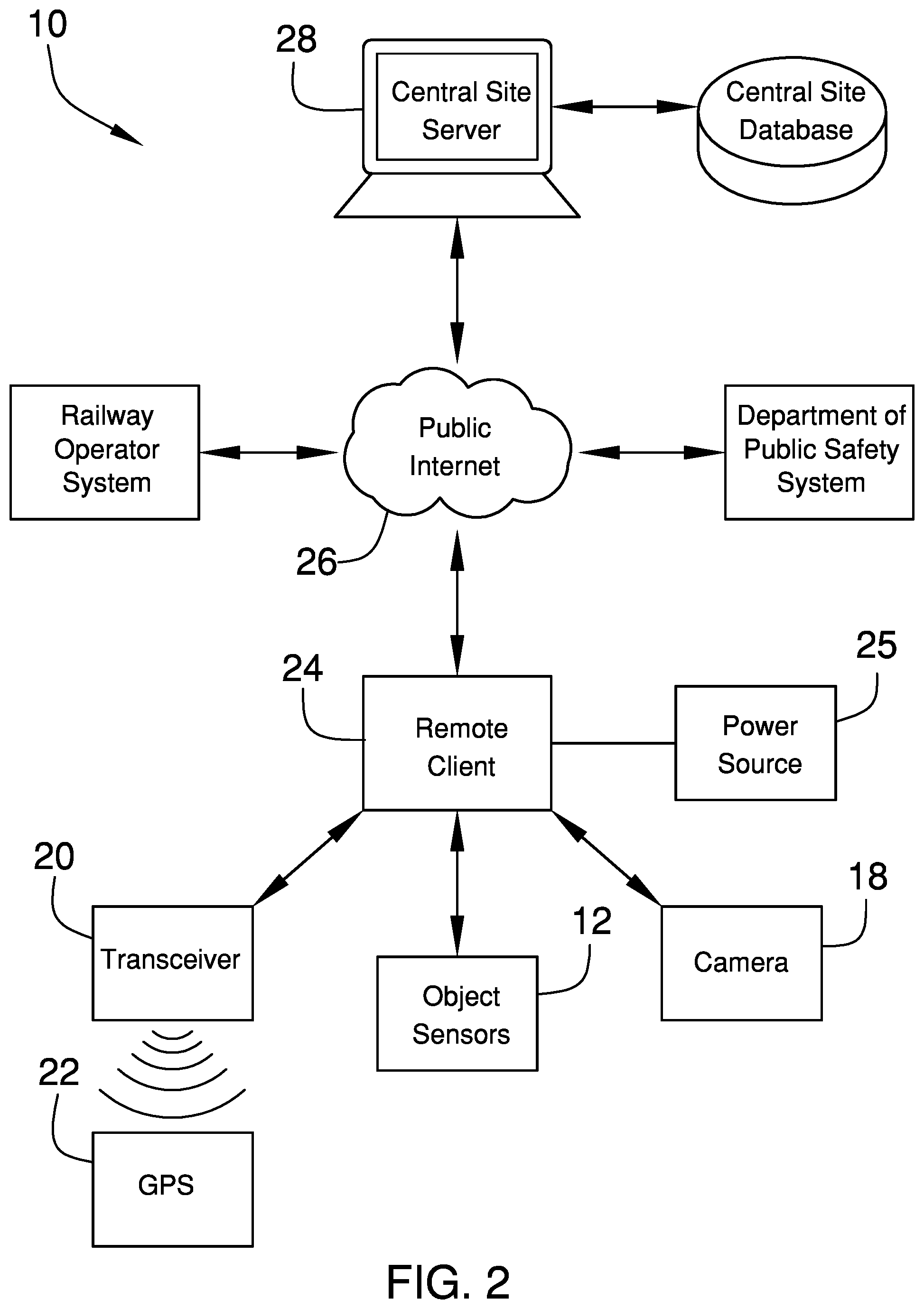
[0011] FIG. 2 is a first schematic view of an embodiment of the disclosure.
[0012] FIG. 3 is a second schematic view of an embodiment of the disclosure.
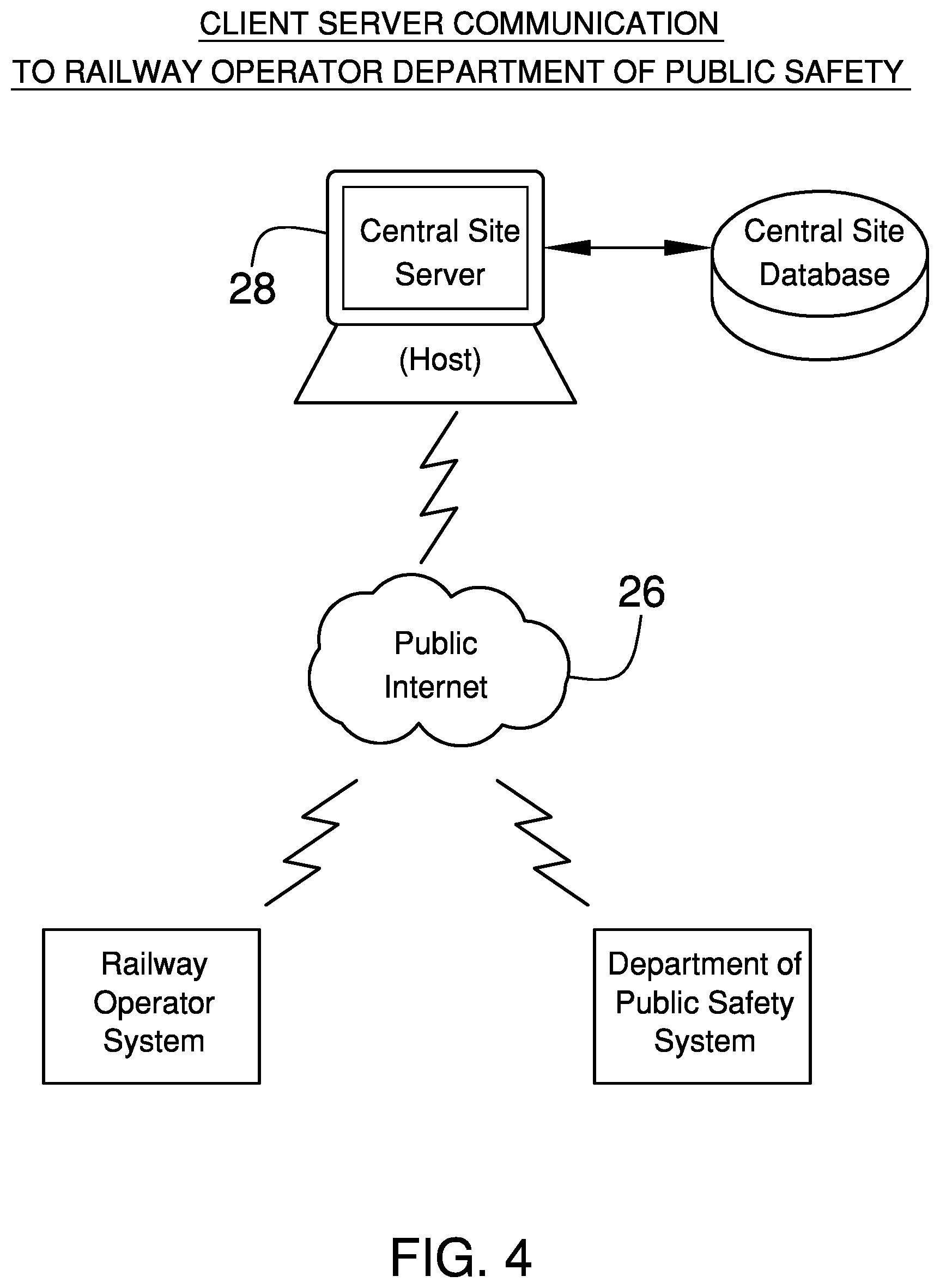
[0013] FIG. 4 is a third schematic view of an embodiment of the disclosure.
DETAILED DESCRIPTION OF THE INVENTION
[0014] With reference now to the drawings, and in particular to FIGS. 1 through 4 thereof, a new railroad safety device embodying the principles and concepts of an embodiment of the disclosure and generally designated by the reference numeral 10 will be described.
[0015] As best illustrated in FIGS. 1 through 4, the railroad crossing safety assembly 10 generally comprises a plurality of object sensors 12 that is each positioned on a respective one of four corners of a railroad crossing 14. In this way each of the object sensors 12 can emit a sensing signal across the railroad crossing 14. Each of the each of the object sensors 12 is arranged to direct the sensing signal diagonally across the railroad crossing 14. In this way each of the object sensors 12 can detect an obstruction 16 on the railroad crossing 14. Each of the object sensors 12 comprises an electronic object sensor, including but not being limited to, laser light emitters, electronic motion sensors or any other electronic means of detecting a solid object.
[0016] A plurality of cameras 18 is provided and each of the cameras 18 is positioned around the railroad crossing 14 to capture images of the railroad crossing 14. Each of the cameras 18 is turned on when any of the object sensors 12 senses the obstruction 16. In this way each of the cameras 18 captures images of the obstruction 16. Each of the cameras 18 may comprise a digital video camera or the like. A transceiver 20 is positioned adjacent to the railroad crossing 14 and the transceiver 20 is in remote communication with a global positioning system (gps) 22. In this way the transceiver 20 can receive a physical location of the railroad crossing 14. The transceiver 20 may be a radio frequency transceiver or the like.
[0017] A data storage unit 24 is provided and each of the object sensors 12 is in electrical communication with the data storage unit 24. Additionally, each of the cameras 18 is in electrical communication with the data storage unit 24. The data storage unit 24 receives the images from the cameras 18 when any of the object sensors 12 senses the obstruction 16. The transceiver 20 is in electrical communication with the data storage unit 24. The transceiver 20 communicates the physical location of the railroad crossing 14 to the data storage unit 24 when any of the object sensors 12 senses the obstruction 16. The data storage unit 24 may comprise, but not be limited to, a personal computer, solid state memory banks or any other type of electronic data storage. Each of the object sensors 12, the cameras 18, the transceiver 20 and the data storage unit 24 are electrically coupled to a power source 25 that may comprise an electrical utility service line or the like.
[0018] The data storage unit 24 is in electrical communication with an extrinsic communication network 26, including but not being limited to, the internet or a cellphone network. In this way the data storage unit 24 is in communication with emergency responders, such as local police or fire departments, thereby facilitating the emergency responders to be notified of the obstruction 16 on the railroad crossing 14. Moreover, the data storage unit 24 is in communication with a railway operation department. In this way the railway operation department can alter railway scheduling in response to the obstruction 16.
[0019] A data server 28 is provided and the data server 28 is in electrical communication with the extrinsic communication network 26. In this way the data server 28 is in communication with the data storage unit 24. The data server 28 receives the images from the cameras 18 and the physical location of the railroad crossing 14 from the data storage unit 24. Moreover, the data server 28 compiles the images and the physical location into a database stored on the data server 28 for subsequent analysis.
[0020] The data server 28 may be positioned in an operations headquarters of a company that is contracted to monitor railroad crossings or the like. A representative of the company can employ the data server 28 to remotely access the data storage unit 24. In this way the representative can send the images and the physical location to the emergency responders and the railway operation department in response to the obstruction 16. FIG. 3 of an embodiment of the disclosure shows a schematic of potential communication between the data storage unit 24 and the data server 28. FIG. 4 of an embodiment of the disclosure shows a schematic of a potential communication between the emergency responders, the railroad operations department and the data server 28.
[0021] In use, the object sensors 12 sense an obstruction 16, such as a vehicle or any other solid object that is positioned on the railroad crossing 14. The cameras 18 are turned on the capture images of the obstruction 16. The images of the obstruction 16 and the physical location of the railroad crossing 14 are communicated to the data storage unit 24. The data storage unit 24 subsequently communicates the images of the obstruction 16 and the physical location of the railroad crossing 14 to the data server 28, the emergency responders and the railway operations department. In this way emergency responders can immediately respond to the obstruction 16 and the railway operations department can make any scheduling changes to avoid a crash at the railroad crossing 14.
[0022] With respect to the above description then, it is to be realized that the optimum dimensional relationships for the parts of an embodiment enabled by the disclosure, to include variations in size, materials, shape, form, function and manner of operation, assembly and use, are deemed readily apparent and obvious to one skilled in the art, and all equivalent relationships to those illustrated in the drawings and described in the specification are intended to be encompassed by an embodiment of the disclosure.
[0023] Therefore, the foregoing is considered as illustrative only of the principles of the disclosure. Further, since numerous modifications and changes will readily occur to those skilled in the art, it is not desired to limit the disclosure to the exact construction and operation shown and described, and accordingly, all suitable modifications and equivalents may be resorted to, falling within the scope of the disclosure. In this patent document, the word "comprising" is used in its non-limiting sense to mean that items following the word are included, but items not specifically mentioned are not excluded. A reference to an element by the indefinite article "a" does not exclude the possibility that more than one of the element is present, unless the context clearly requires that there be only one of the elements.
* * * * *
D00000
D00001
D00002
D00003
D00004
XML
uspto.report is an independent third-party trademark research tool that is not affiliated, endorsed, or sponsored by the United States Patent and Trademark Office (USPTO) or any other governmental organization. The information provided by uspto.report is based on publicly available data at the time of writing and is intended for informational purposes only.
While we strive to provide accurate and up-to-date information, we do not guarantee the accuracy, completeness, reliability, or suitability of the information displayed on this site. The use of this site is at your own risk. Any reliance you place on such information is therefore strictly at your own risk.
All official trademark data, including owner information, should be verified by visiting the official USPTO website at www.uspto.gov. This site is not intended to replace professional legal advice and should not be used as a substitute for consulting with a legal professional who is knowledgeable about trademark law.